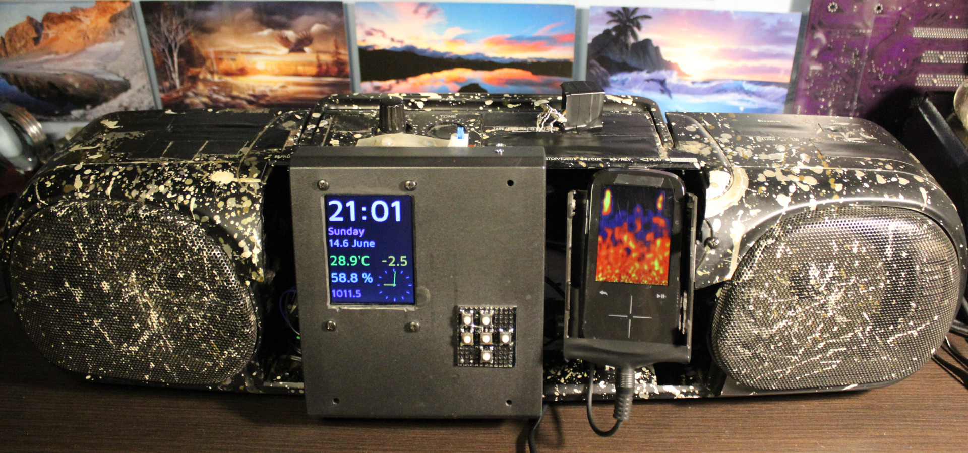
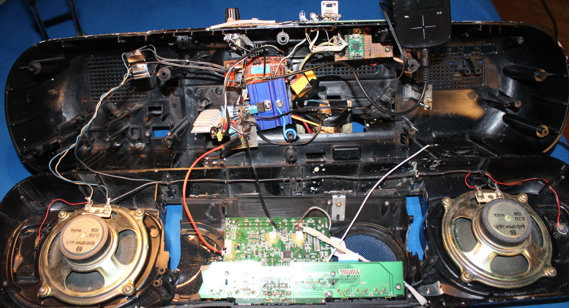
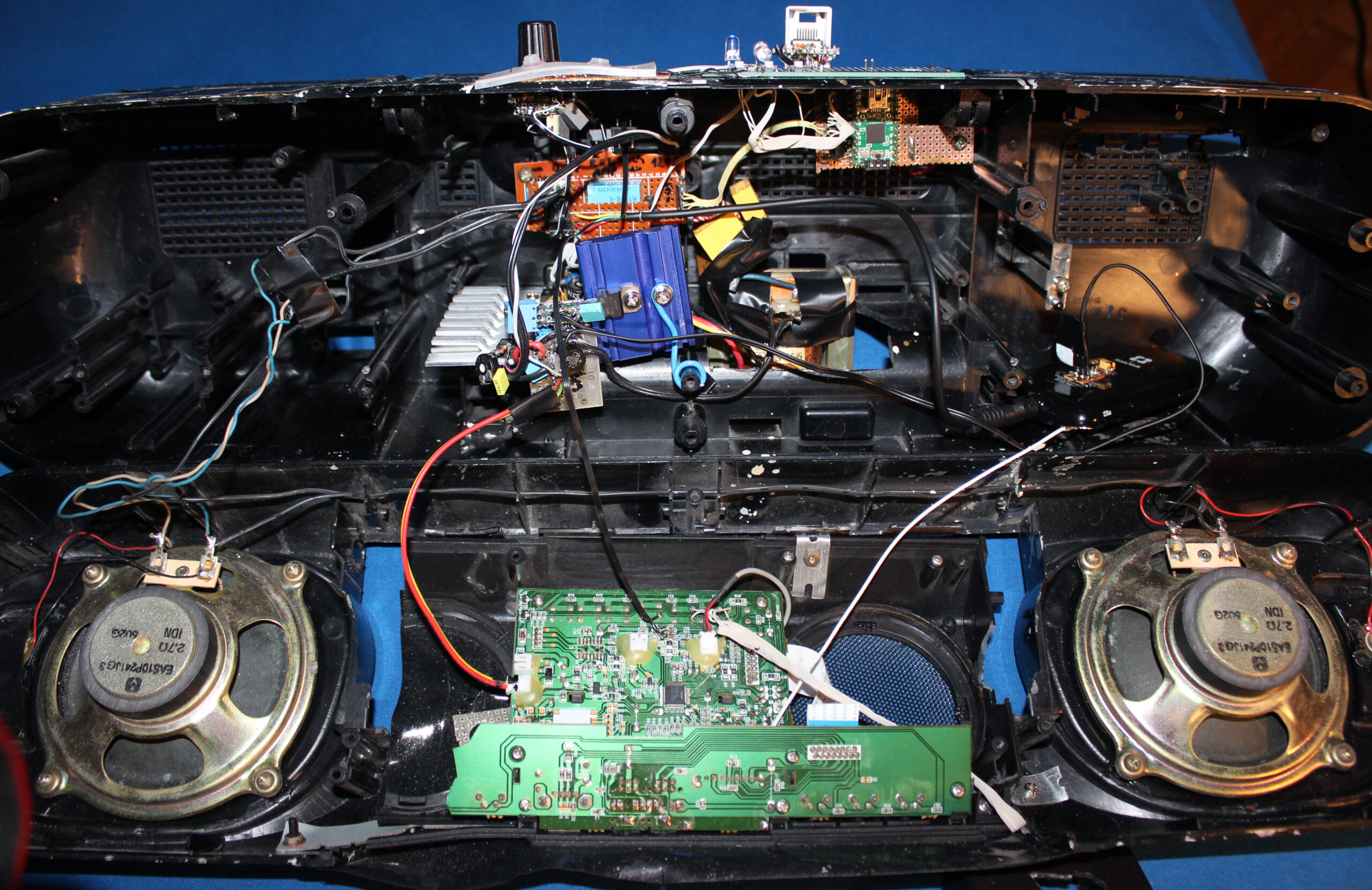
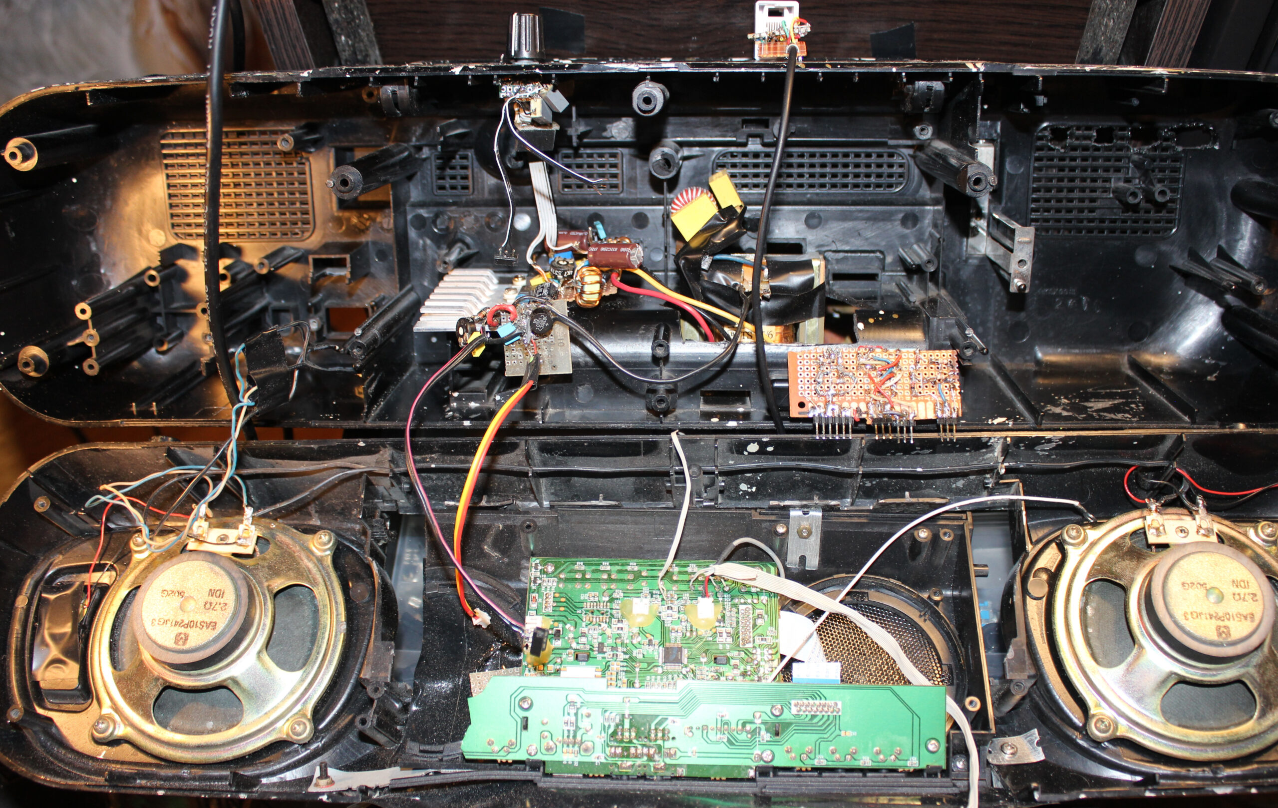
This is a continuation of (a long and probably boring, yet few times already coming back topic of) my modifications to an old HiFi. Which we use in kitchen, for showing clock (my weather station) and listening to music. Now I put both player and clock inside, between speakers. I also got rid of my old power supply and made it use less power and lighter too.
📜History
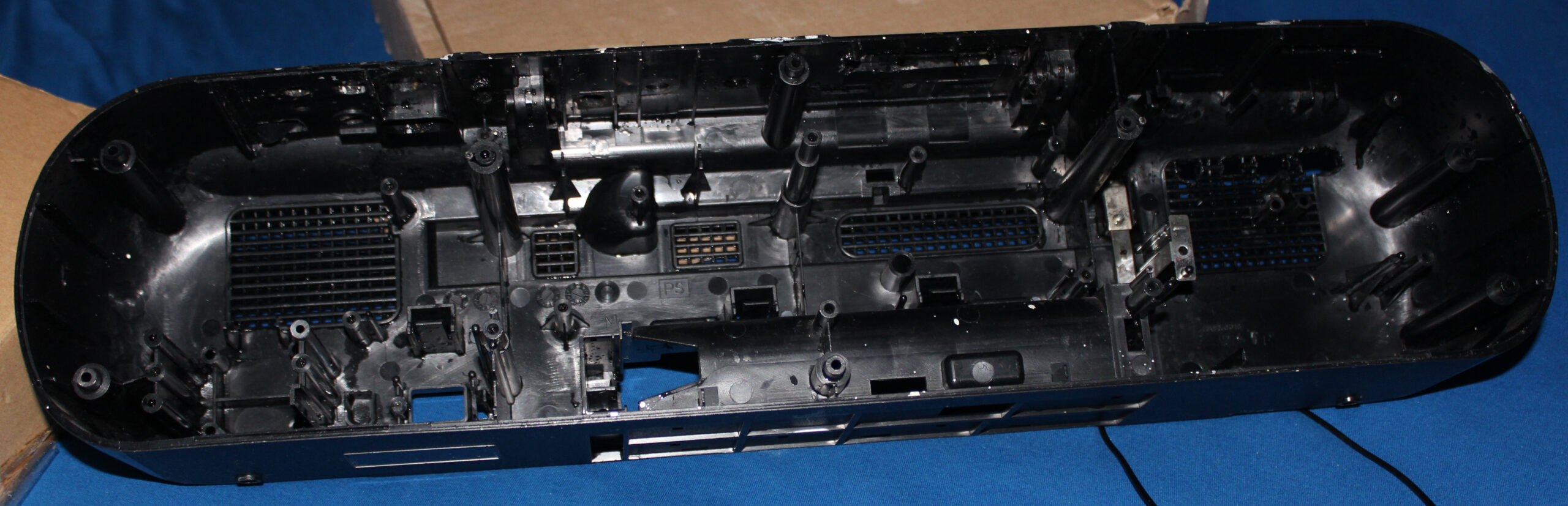
It all started a very long time ago in 1997, in a different age when cassettes📼 were roaming the Earth🦒. Back then I got this Panasonic RX-FT530 Dual Cassette Player/Recorder (original pictures). Not long after I started modifying it with what I could, to suit my needs and make it more usable (e.g. LED lights, faster spooling etc).
This is covered in detail in first project. On that page still, I did a major thing in 2020, by throwing out not used cassette decks, and mounting (or should I say butchering🪓) a digital radio (without its speakers) inside here, just between this HiFi’s speakers. Then connecting it and making a nice source switch between radio and player, using MCU and relays, with buttons and LEDs. Also added another source later from my PC, through ceiling and long cable.
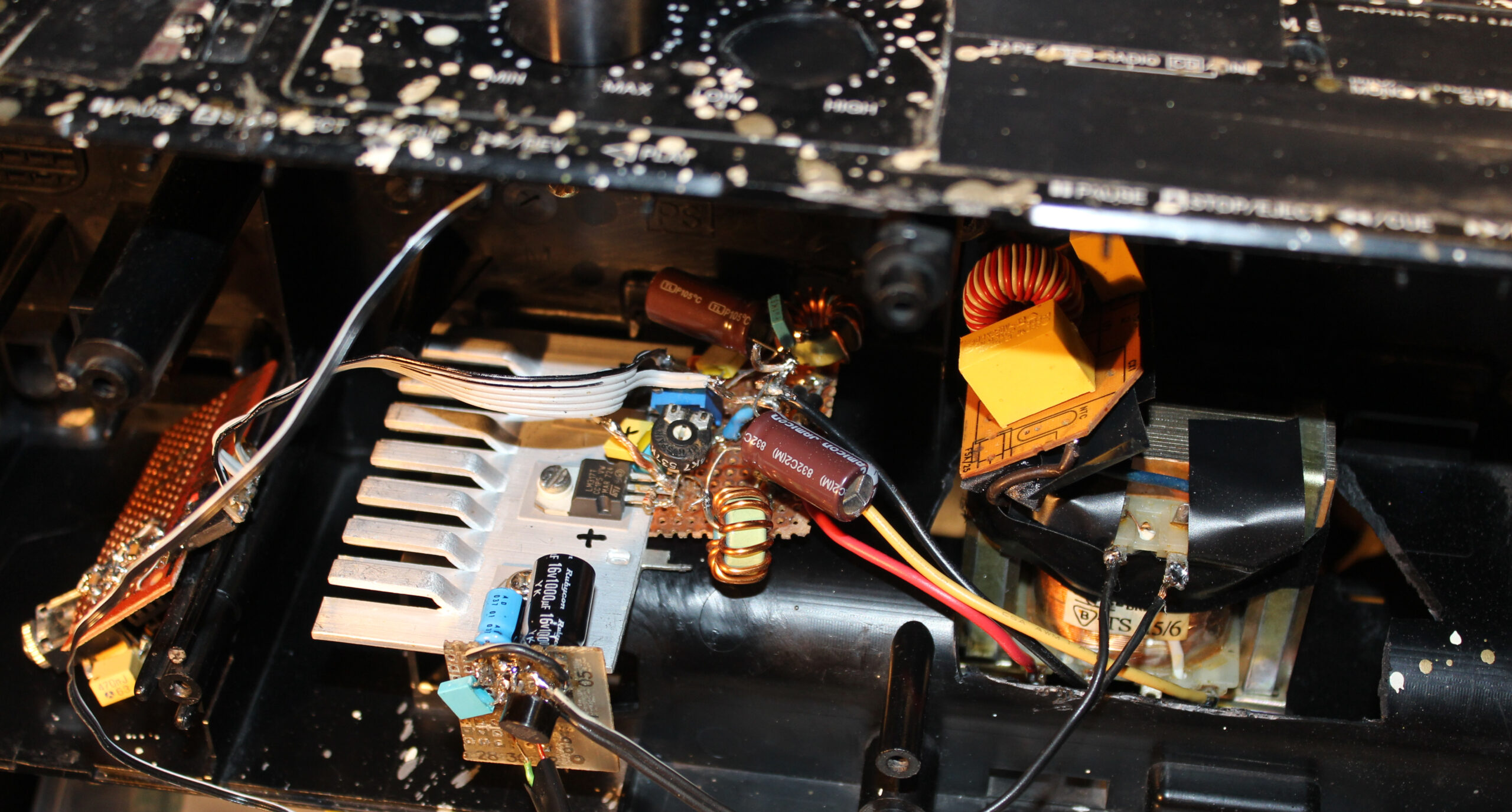
Later in 2023 second project I got rid of all original PCBs, amplifier and power supply. I made my own (still from a transformer) with 2 voltages and +-16 V voltage regulators. Back then I still was convinced that’s the way (OP275 op amp pdf says it makes less noise so). And it was how I did it earlier too in my guitar distortion effect. Unfortunately these regulators give heat and waste too much power. So it was going to be an issue for me later.
✍️Motivation
For a while this digital radio was okay and used. I recently bought a tiny TEA5767 FM Radio Module (e.g. here). So the radio could likely be just that small. And could replace the whole digital radio here. Which isn’t really used today by us now.
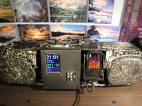
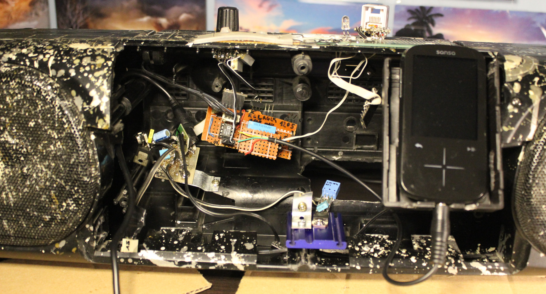
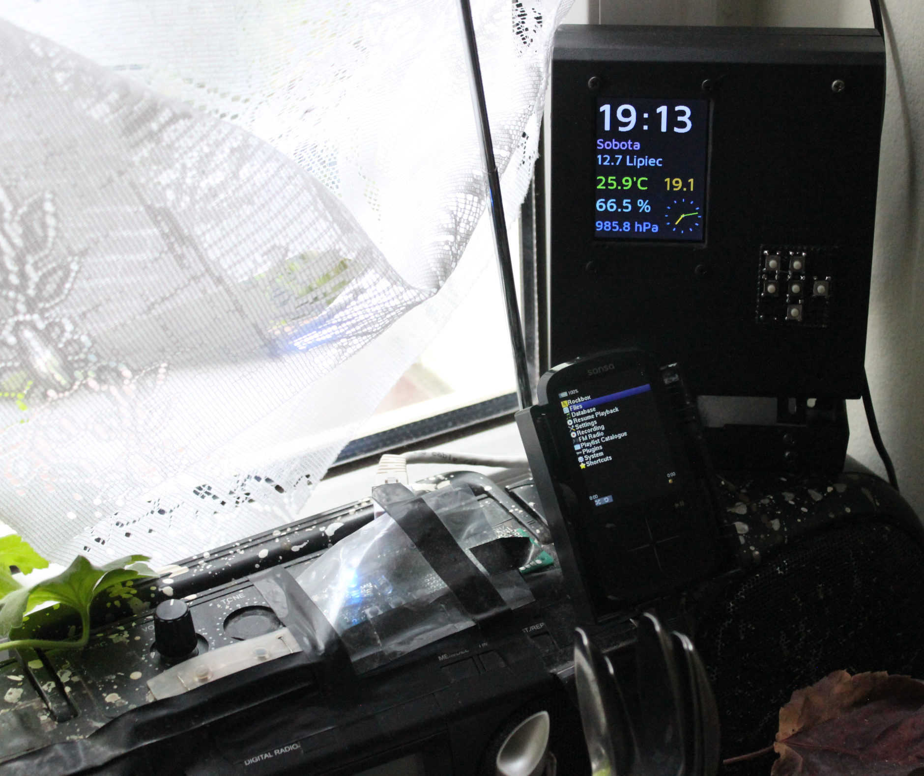
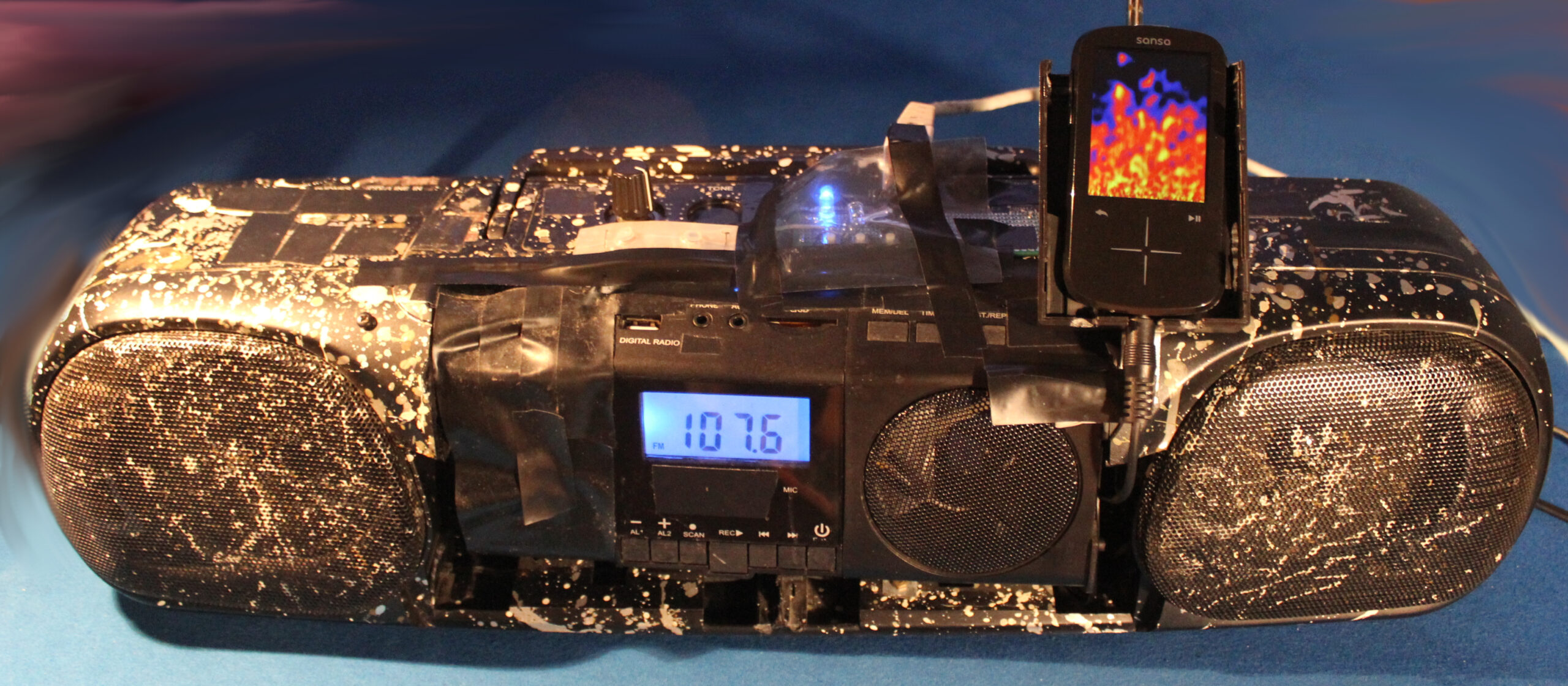
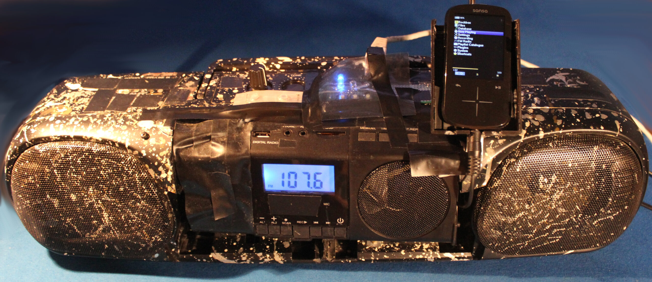
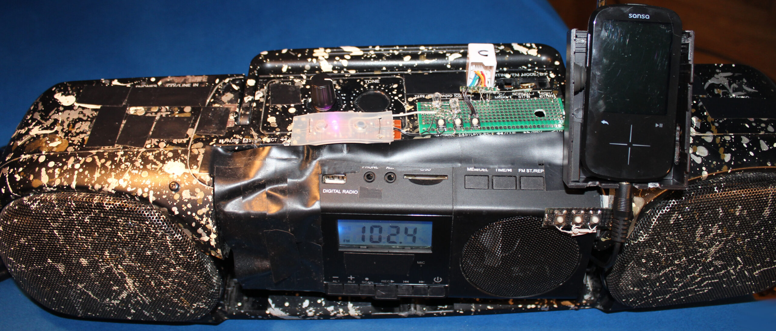
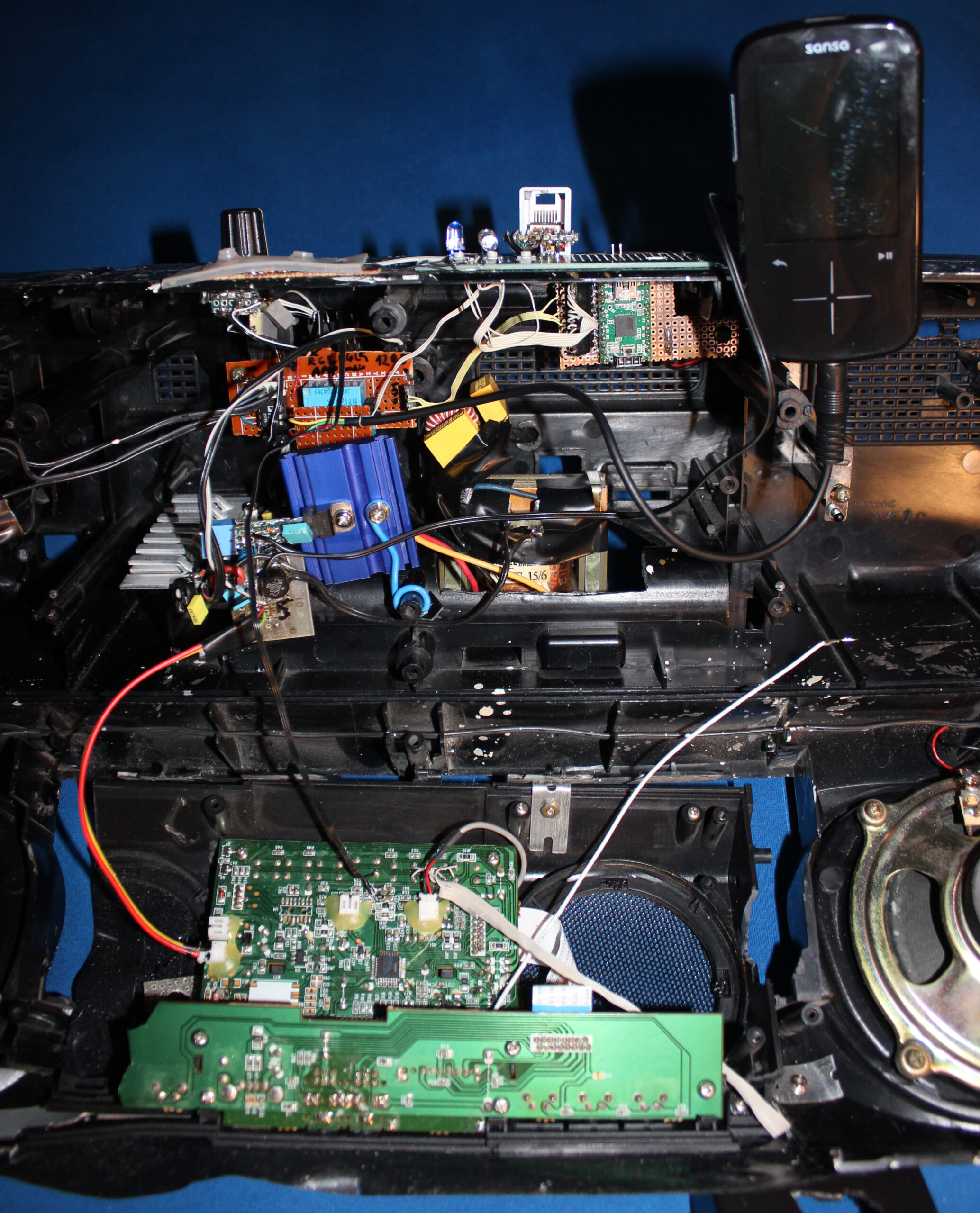
There was no space for my music player (Sansa Fuze+ with RockBox), so I mounted in on this HiFi. Later when I made the weather station, I also mounted it on this HiFi. The picture here, shows both. Sure it was usable and needed, but it doesn’t look great, rather crowded and separated.
Another reason was the high power use of this HiFi (about 3 to 5W), due to my old transformer based power supply with too many voltage regulators.
Both finally made me rework this thing once again.
📊Features
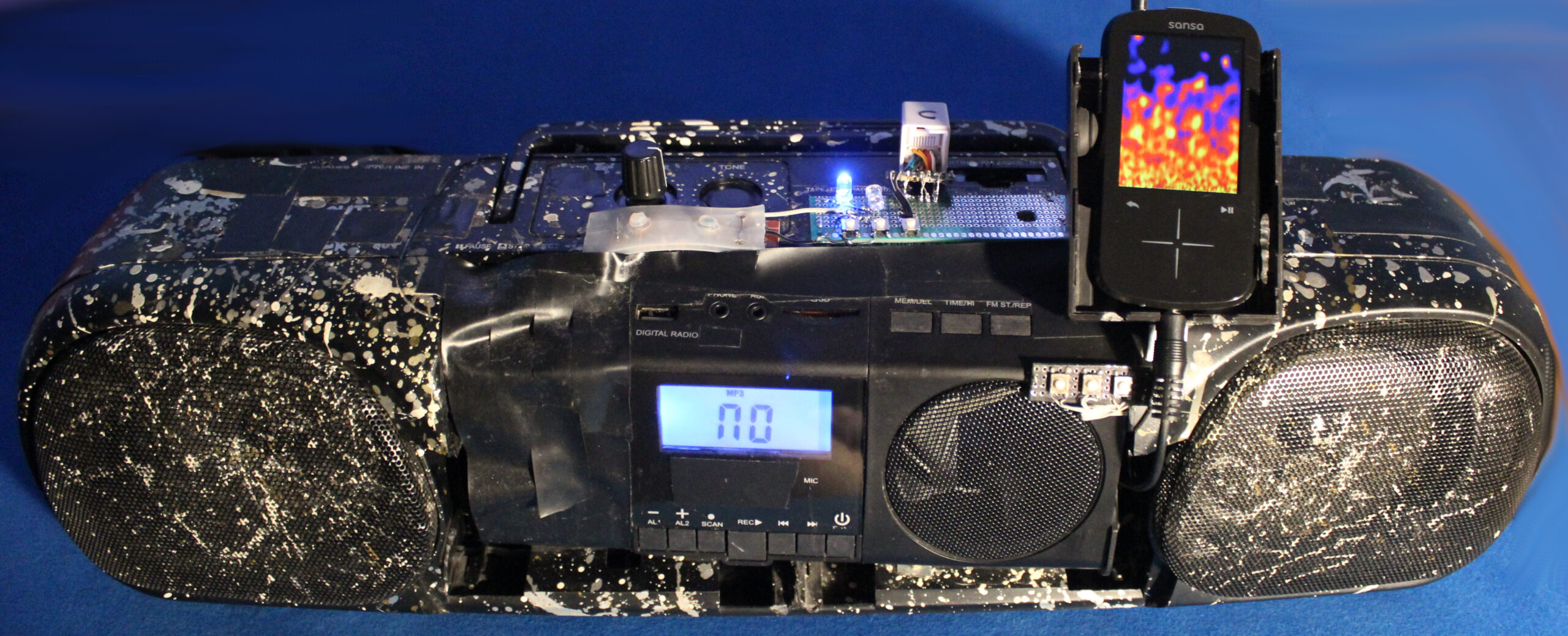
For now I got rid of the radio. It’s a further thing to do. Possibly not needed at all. I also got rid of that MCU and source switch. It’s only the music player here.
It now uses an impulse 12V power supply, which is not even inside, but near power outlet, like so many devices nowadays.
There rest stayed nearly the same,
⌛Conclusions
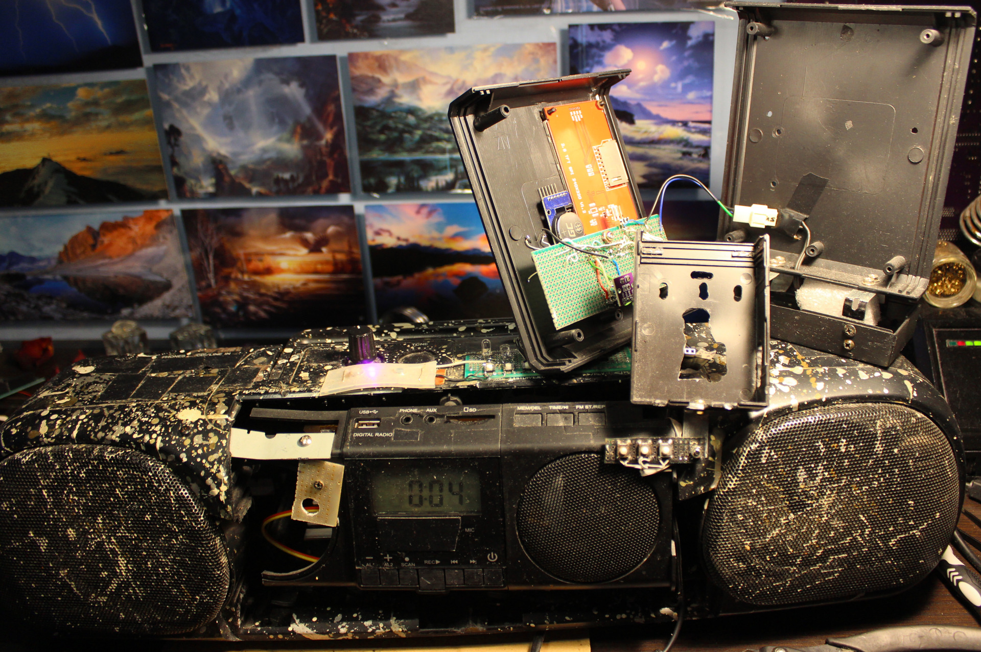
It does use less power. Now 2.4 W when playing not 5W. The audio amplifier section is only 0.3W (or less) now. Looks like my Esp32 clock needs 1.5W (way too much for me) and that player 0.9W or so.
It is lighter too. Weighs less mainly because there is no old, metal transformer anymore here for power supply.
It’s even smaller. Because those needed extensions from top of HiFi got moved inside.
It was done probably too quick, still it took 2 days to finish. As always there is a rush with this thing, as I need to listen to music in kitchen and not have this HiFi being under rework.
Another thing as always, it needs an extra step of cleaning. This thing (after years) always gathers dust. Since it has holes, it also gets inside, even natural stuff from outside as window gets opened during spring.
So I had to postpone the thing I actually wanted to do most since a while: using this clock’s ESP32 with display to also feature radio and audio player in one device. It’d be best to do it first on other ESP32 as it’d be slower to develop, while kitchen HiFi is used few times daily.
Well with this project as with my keyboards too it’s usually my history of learning how to do things and making few working (but not best) things along the way (years apart due to other projects). Looking back at those previous, even ridiculous versions I could say those were not needed or a waste of time. But that’s just how I learned that. Usually I need a working thing faster, not first spending a week on developing the best possible version.
Lastly it is nearing its 30 year anniversary, even if just case and speakers are left from its 1997 original. So it got a long life, instead of ending in garbage like so many such products, renewed and produced yearly or so.
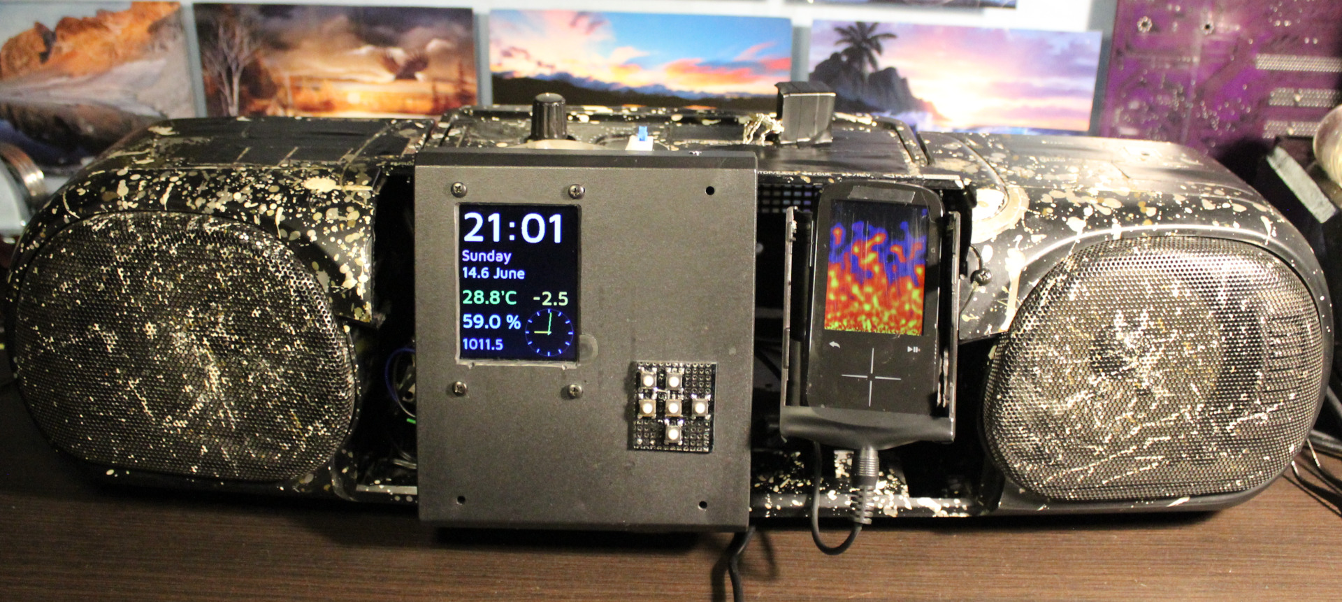
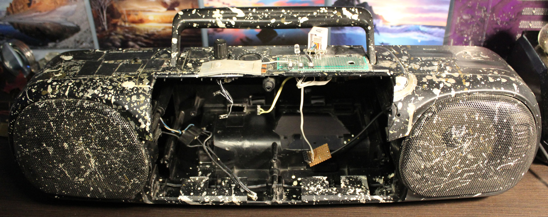
📷Gallery
Just a few pictures. Much got removed, nothing new added.
This project is a PC mouse modification with very light press keys, using mini magnets.
📝Motivation
I have been using my keyboards with modified keys since 2004. They have been nice and a joy to use, less tiring too, since I cut off the rubber domes to reduce force. Still there are limits from the foil beneath. They are better also from medical reasons, less force means: less fatigue, less likely injuries, etc. It’d be good if the freaking old industry didn’t sell old crap for 50 years. As with keyboards now just with added RGB lights or even big display under, or small for for each key, etc. To maximize cost and profits and cash on the stupidity and looks instead of functionality, ergonomics, productivity. Yeah whatever, that’s why I do it myself (DIY).
Since years I’ve been using my latest keyboard (has a display and my own firmware) with Layer 2 having keys for mouse buttons, mouse move and mouse wheel with acceleration. It is much better to use (than those real from a mouse) because these are now light press keys (about 20 gram).
It’s been way too many years (over 30) of me using the default PC mouse with those ancient old microswitches. It’s just retarded for me nowadays. They usually need like 75 gram force (gf or cN) to press, have that old click sound. And the button under mouse wheel needs even more, like 100 gram. At least that’s what my previous (20 year old) mouse Logitech G5 has: OMRON D2FC-F-7N (10M) which says 0.74N (N to gram convert), cool websites with that switch here or here, video here, images.
▶️Video
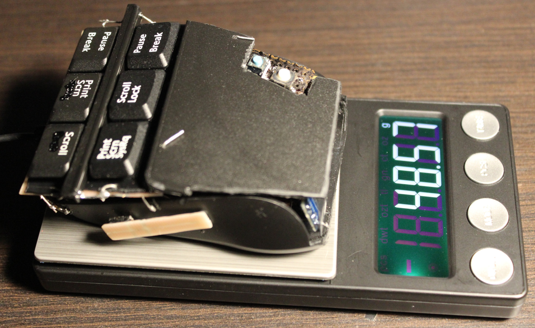
Video here. Shows inside, weights testing, and at end blowing air to press.
🔍Details
Here I write (a lot) more detail of my approach for keys, with comments.
Keys
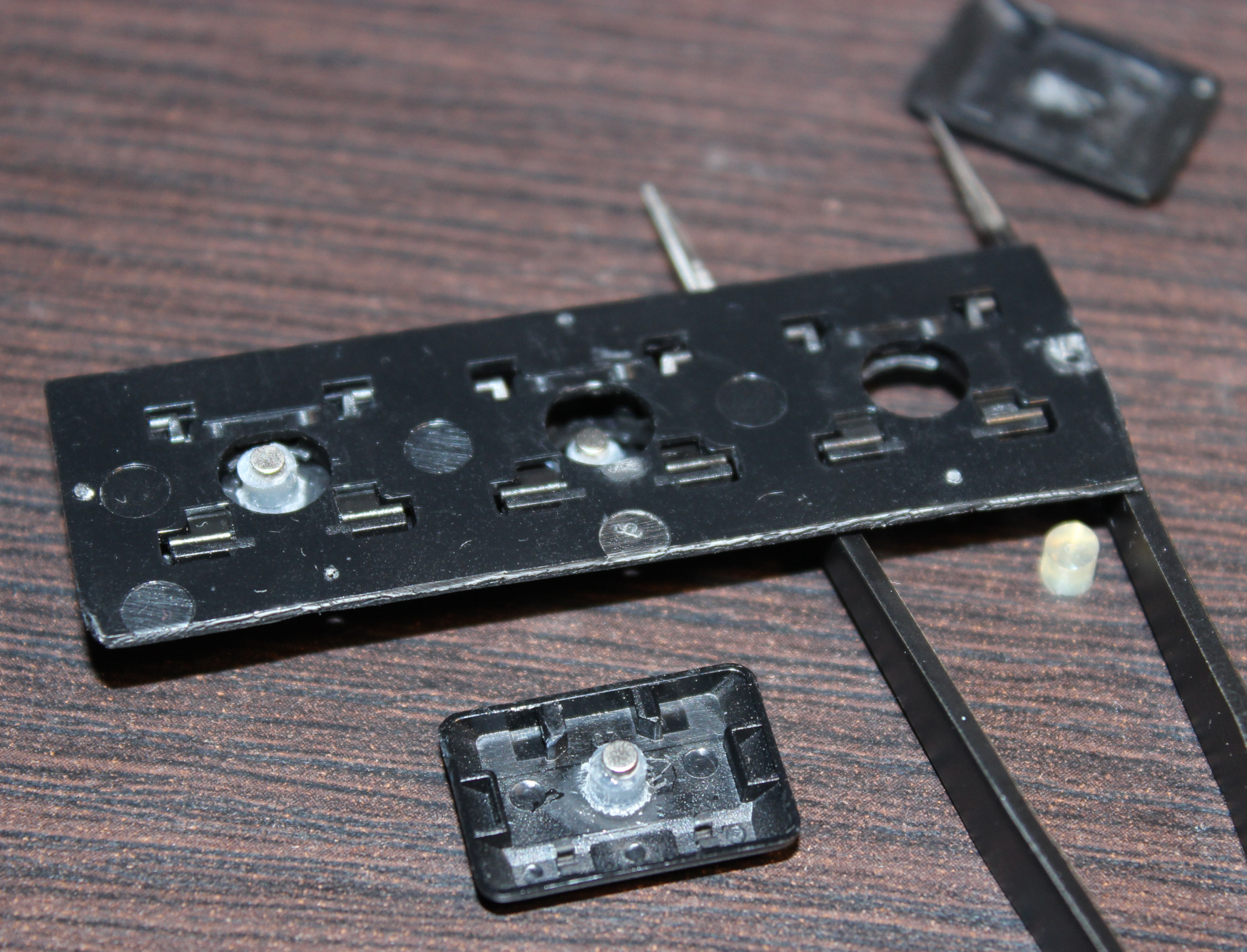
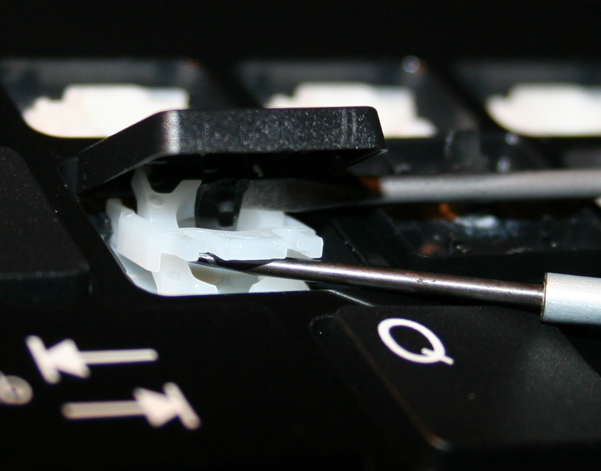
Keys are from keyboard (scissor switches), those narrow (like F12). But now for each key I use a Hall sensor (CS49E, SMD) and 2 tiny magnets. Thus so called mag-lev (levitation), since these magnets push each other out. There is no spring, no rubber just small magnetic force, making it much lighter and IMO say more reliable.
I saw earlier this page with video of another such way. And also there are a few keyboards already produced with such design. It’s just that they still have long travel and way too high press force, some still non linear press too. Obviously a nope for me.
Result
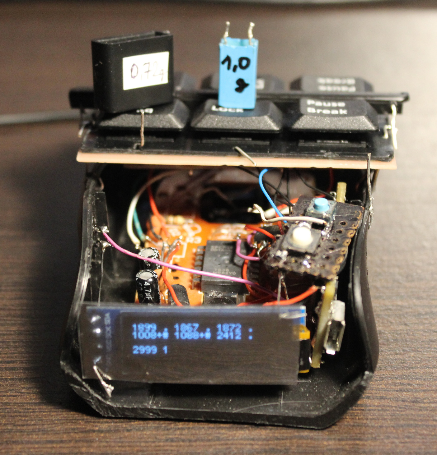
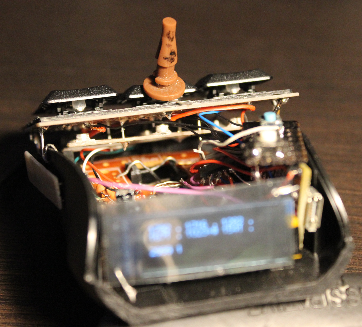
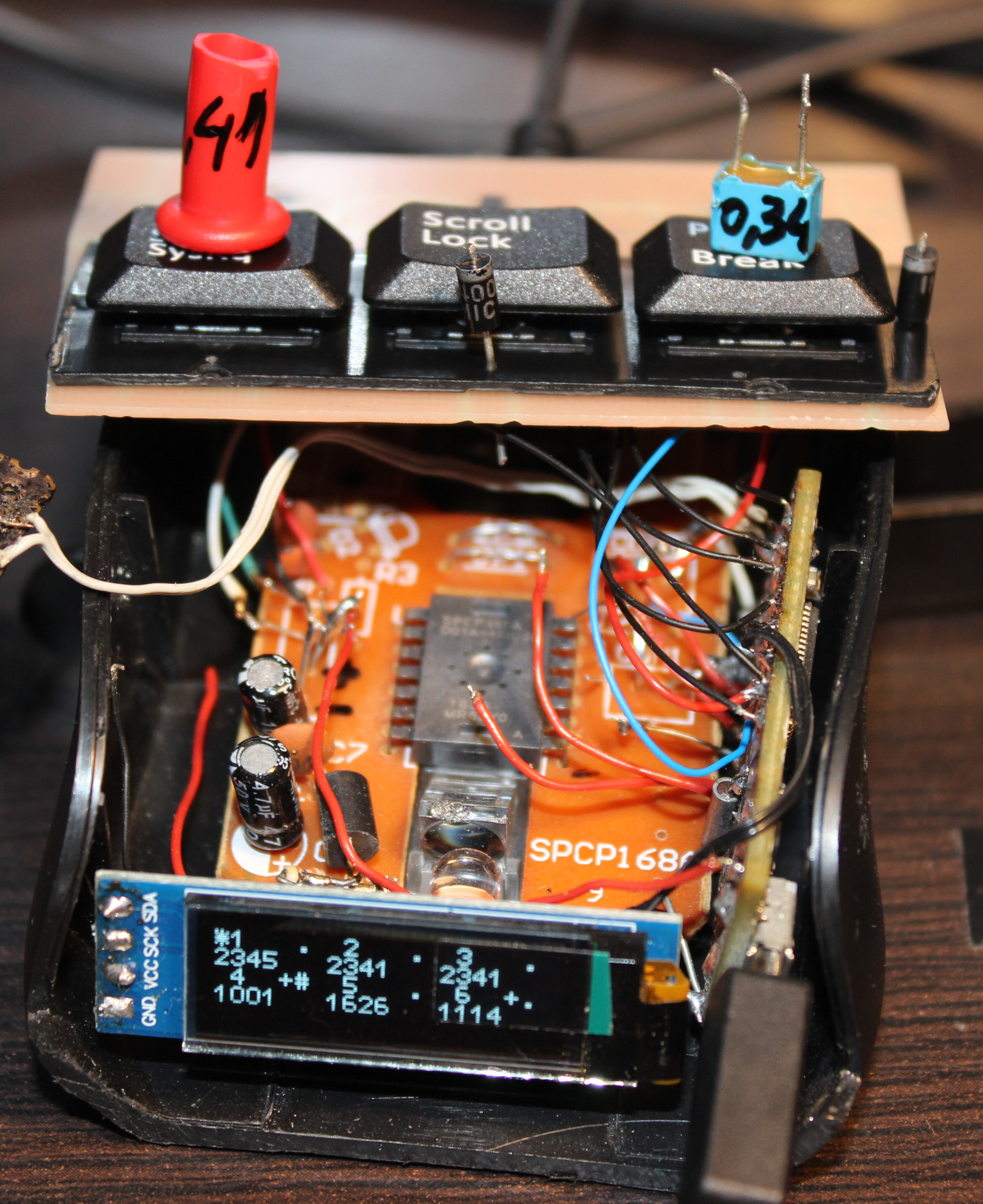
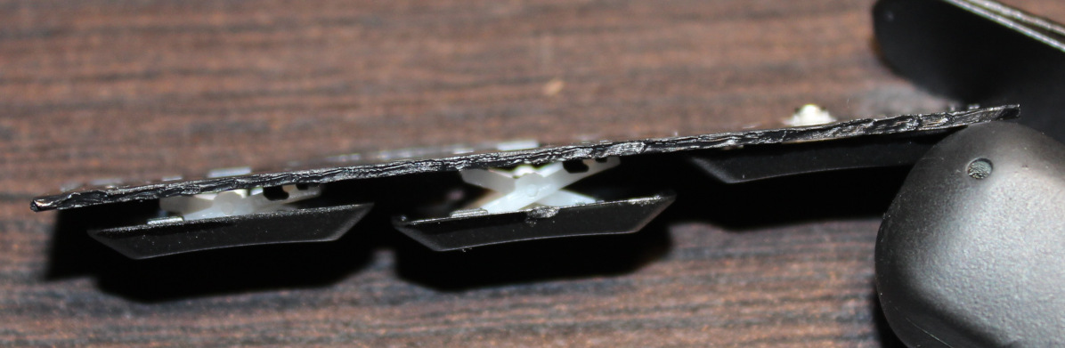
The resulting press force is way lower. I managed to get it even to 0.34 gram. It’s incredibly low, you can just put a tiny M3 screw on key to press. Or even blowing air to press works🌬️. I set it later to around 0.7 or 1 gram force. Of course this creates another problem, that you can’t rest your fingers on keys now. That’s why I put this plastic bar between keys for fingers to rest.
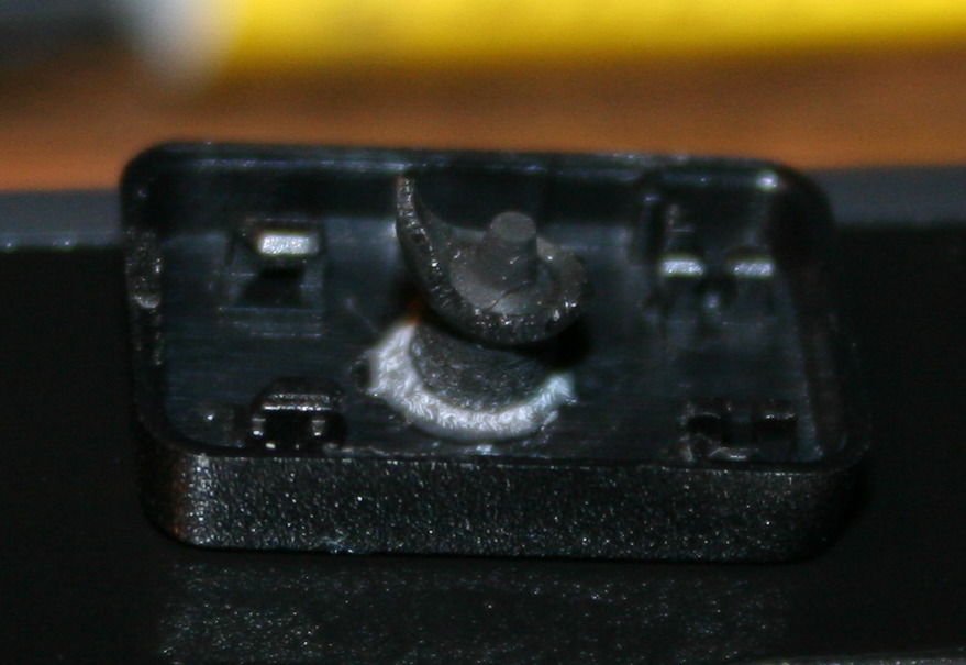
Silicone cylinder🛢️
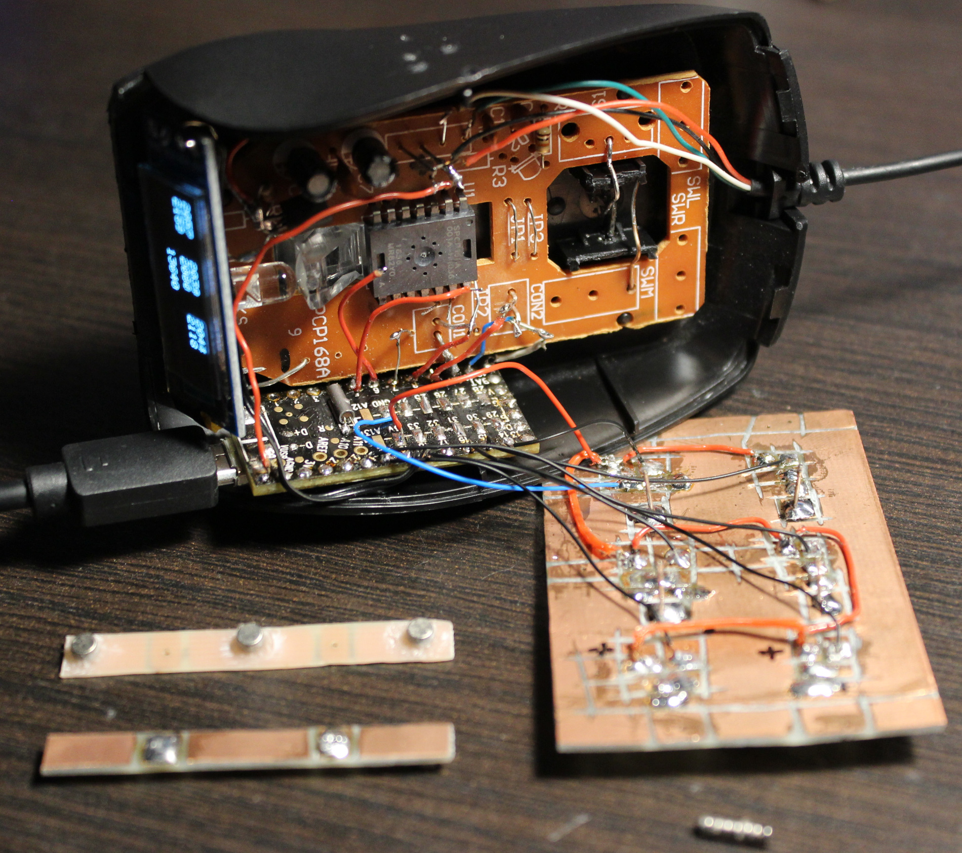
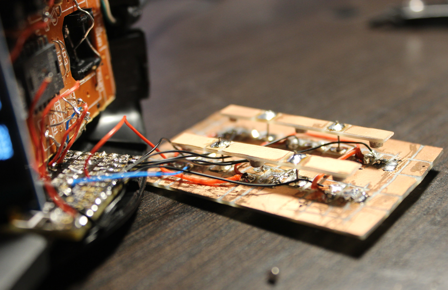
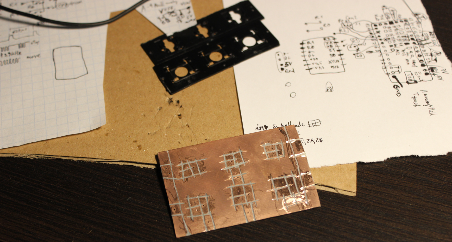
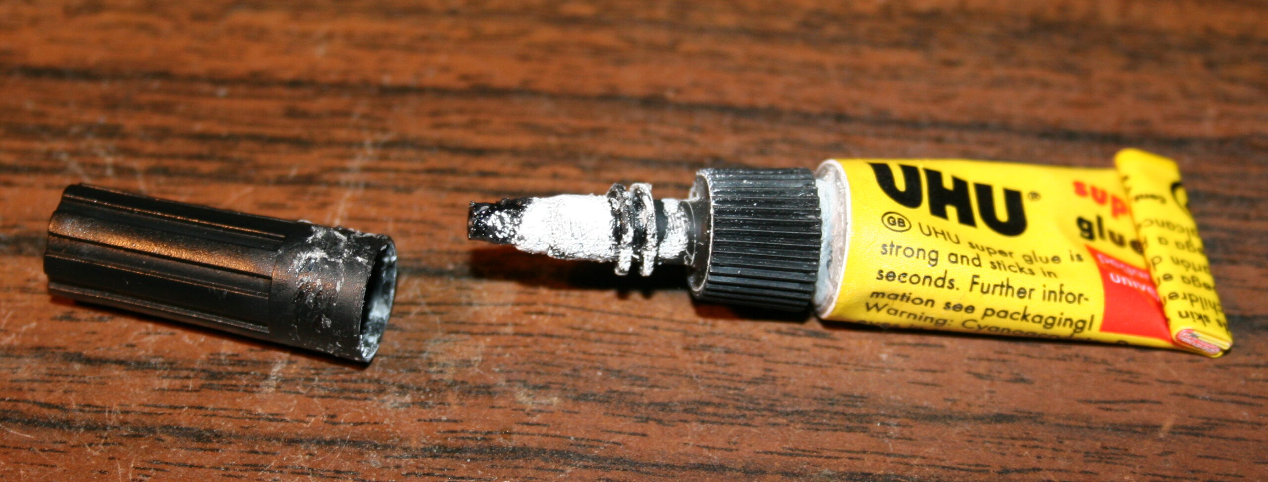
The top of key has beneath a (super) glued silicone pad (3mm diameter cylinder (I bought silicone rope and cut it), *height about 2.5 to 3.1 mm). Then on top of it glued the first mini magnet 2×1 mm (diameter x height). I think the default N42 neodymium🧲. This magnet when pressed touches the CS49E SMD Hall sensor which is on PCB. It could be a 2 layer PCB, but since I got 1 layer, this SMD chip is glued onto it, in right place (middle of plastic circle hole), then through drilled holes, tiny wires are soldered to sensor chip’s 3 leads.
Travel
Travel distance can be changed, but needs cutting *height of that cylinder and glueing magnet again. Or just scraping cylinder and doing a new one with other height. It’s not that precise even if measured, there can be some tolerances in scissor keys etc. So getting exactly 0.5 or 1 mm travel would be hard. It is also possible to add just small tape pad⚫ (from e.g. black isolation tape) for a thin layer on top of sensor. It would decrease travel and also sound less when hit with magnet (2×1) from key. Less sound is also the reason why cylinder is from silicone.
Sensitivity👈
Also the less travel the less sensitivity and value change from Hall sensor. So MCU’s ADC is 12 bit, meaning it could get values from 0 to 4095. But it won’t since CS49E has 3.3V supply and its output has limits, doesn’t go below 1V or higher than 3.3V – 1V. Doesn’t really matter.
So I get about 1000 when pressed (magnet closest) and about 1500 for lightest (0.35 g) setup if done right. But it can be tricky if there is friction in scissor key, I had to slightly cut off a bit. If I didn’t do it you can get 1100 or so, sometimes if key gets stuck (while otherwise it’d go much higher) and that’s a problem (it’s unusable).
As for the regular keys there is no issue: 1742 for 0.72 g, 2146 for 1 g, 2416 for 2.23 g. This is plenty difference from about 1000. Each keys/sensor will have some minor difference too. Not required but could be set up with some calibration for each key in practice.
Magnets🧲
The two magnets distance affects mainly actuation force and sensitivity (max value). The closer they are the more force one needs to press and higher value if not pressed. There was a “interactive 2D magnetic field lines simulation applet” I used before to test best location of sensor and 2 pushing magnets (1 stronger), but I can’t find the website anymore (e.g. this).
In general the first magnet (2×1 on key) needs to be closer to sensor, and get closest when pressed, and the second (3×2) should be far. This way I get most sensitivity. The second magnet when far should not affect the value from first (too much). It’s just there to levitate the key after all.
I glued second magnet (in row for 3 keys) to a narrow PCB, which is held by solder and small wires, above the PCB with sensors. This way I can adjust distance of second magnets and so the force for keys. The key resting values (1742 for 0.72 g, 2146 for 1 g, 2416 for 2.23 g) are increasing, because I did shorter distance of narrow PCB on right (last key value) for Right mouse button and did longer distance (on left) and thus lighter press for the (most commonly used) Left mouse button (first key value).
Customizable🔩
As explained above, the actuation (pressing) force is customizable. Not too easy, but easier than travel. One way is resoldering that narrow board closer (more force) or further away (less).
It’s also possible other way, by adding more magnets (3×2) to the one already there. Makes magnetic push force stronger and so needed actuation force higher. It’s a worse idea since magnets aren’t cheap and one is enough. But it’s surely easier and quicker to adjust this way. So more user friendly.
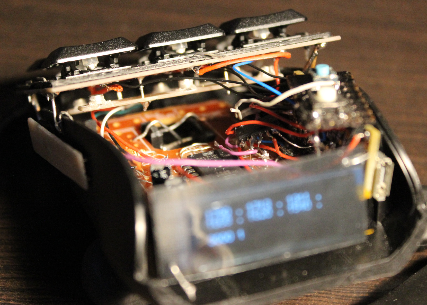
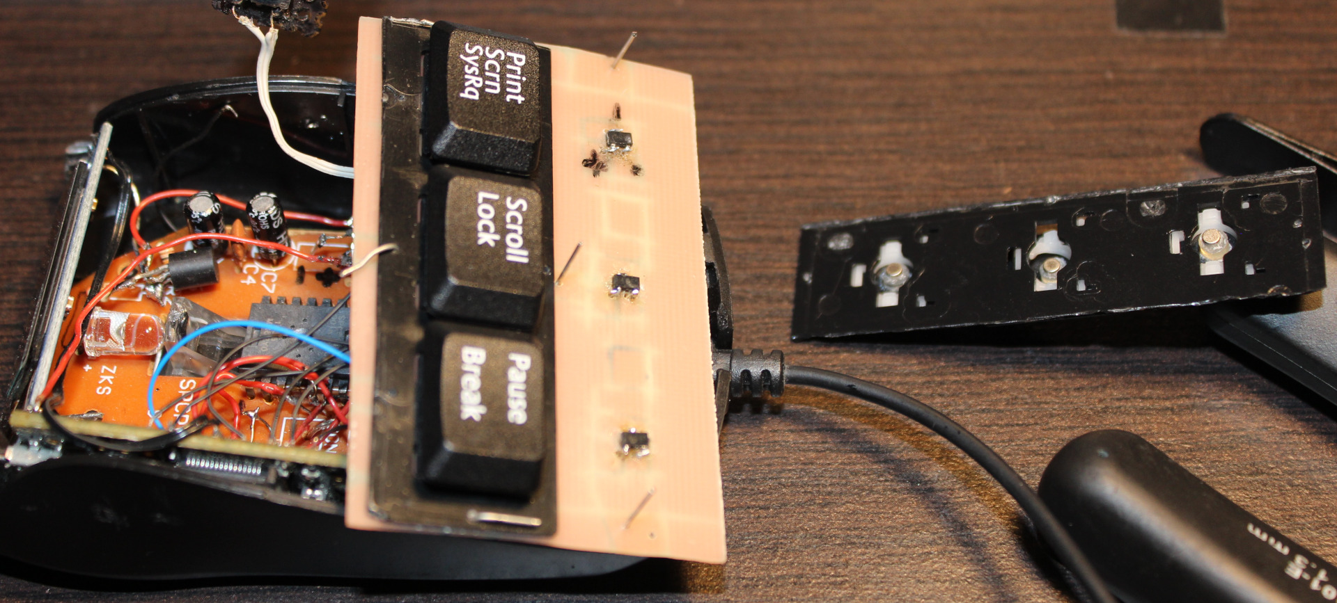
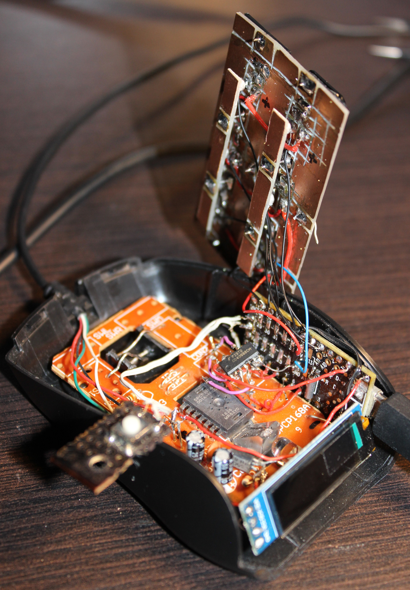
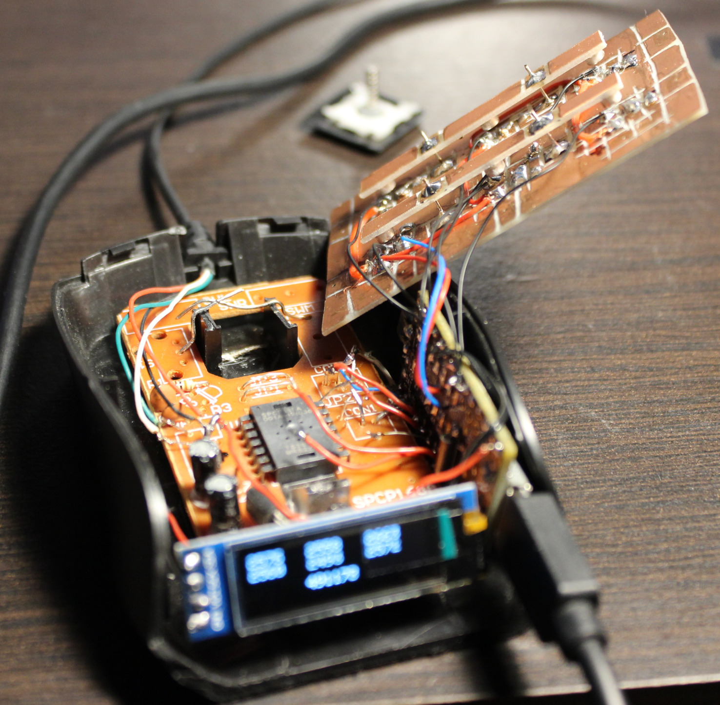
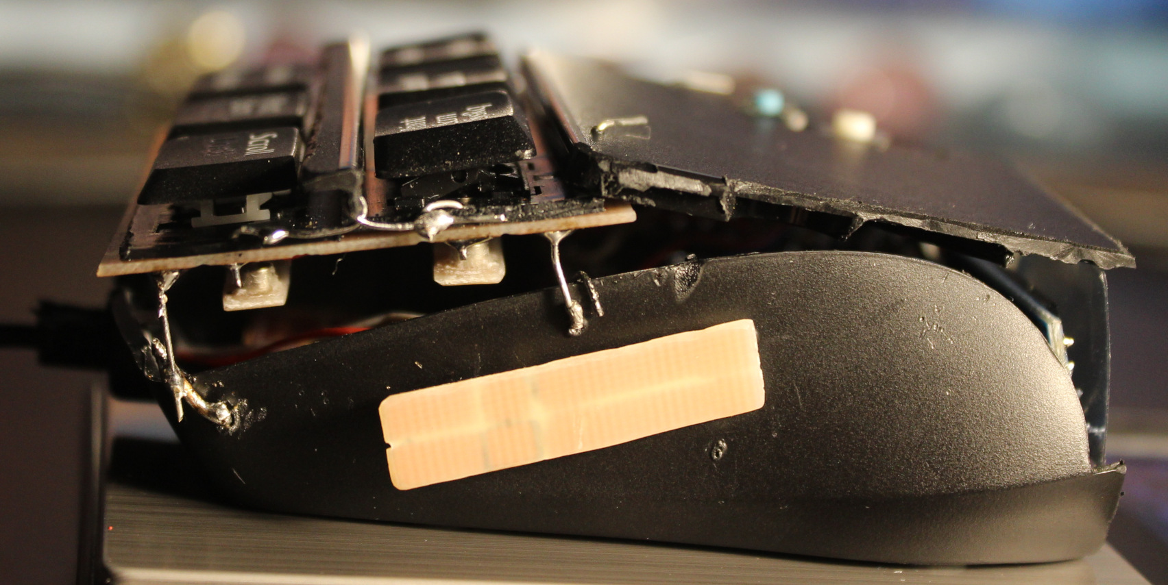
Mouse
Mouse is an old Gembird model, it is small. Not very recognizable anymore after modifying. It has a SPCP168A optical mouse chip. It’s old (from 2010), so not very high dpi. Neither fast pooling, I even saw that L,M,R buttons are checked (by S0 signal) at about 370 Hz only (could mean a 2.7ms delay).
MCU
For MCU I used an old Teensy 3.1 I had from my old keyboards. Surely an ESP32-C3 could be a cheaper and better choice. And likely most MCU could do the job here: just read analog value from ADC from 6 hall sensors. Next I use a CD4066 (SMD, Quad Bilateral Switch). Its 3 analog switches are used instead of old mouse buttons microswitches. Triggered from MCU which reads hall sensors values with some of my code.
📊Features
So the mouse now has a few extra things:
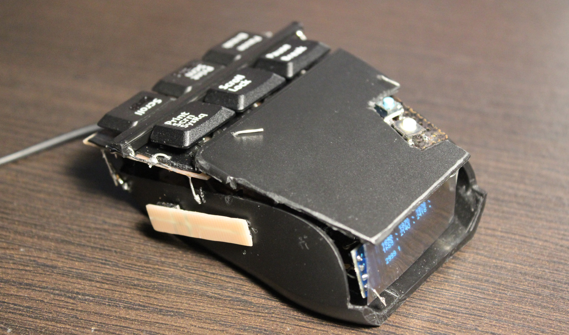
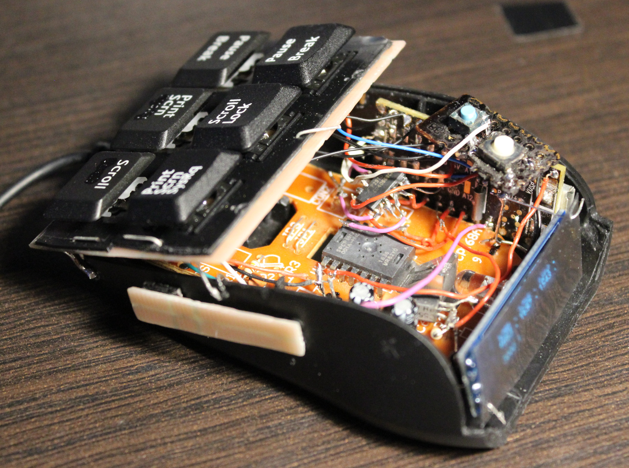
🎹Hall sensor keys, 3 x 2, so total 6. These are used for: – Left, Middle, Right mouse buttons – bottom row, – Double left click, mouse Wheel down and up – top row.
🪟A small OLED display, 128 x 32 (SSD1306), mono (1 color only). Only has 1 dim option, it’s always way too bright. I covered it with some foil. It’s usually off anyway. It is used to show hall sensor values for testing, and for future Gui with settings. It’s optional. It could surely work without it.
🖱️”Lift off” key. That narrow PCB on left side with has tactile switch (SMD, 0,5N force). When held it disables move movement (on PC) and any mouse keys. It is easier to press it than lifting a mouse. I mean seriously and it’s not common in mice yet.
👇2 extra tactile switches: – 1st for toggling display / Gui on/off – 2nd tiny blue for programming new code. There is also a micro USB socket for Teensy 3, needs to be there to upload new code.
📂Sources
Code for this “firmware” is here. Schematic image here. I called it MC1, from mouse controller, even if it’s not really one. Just code for those keys
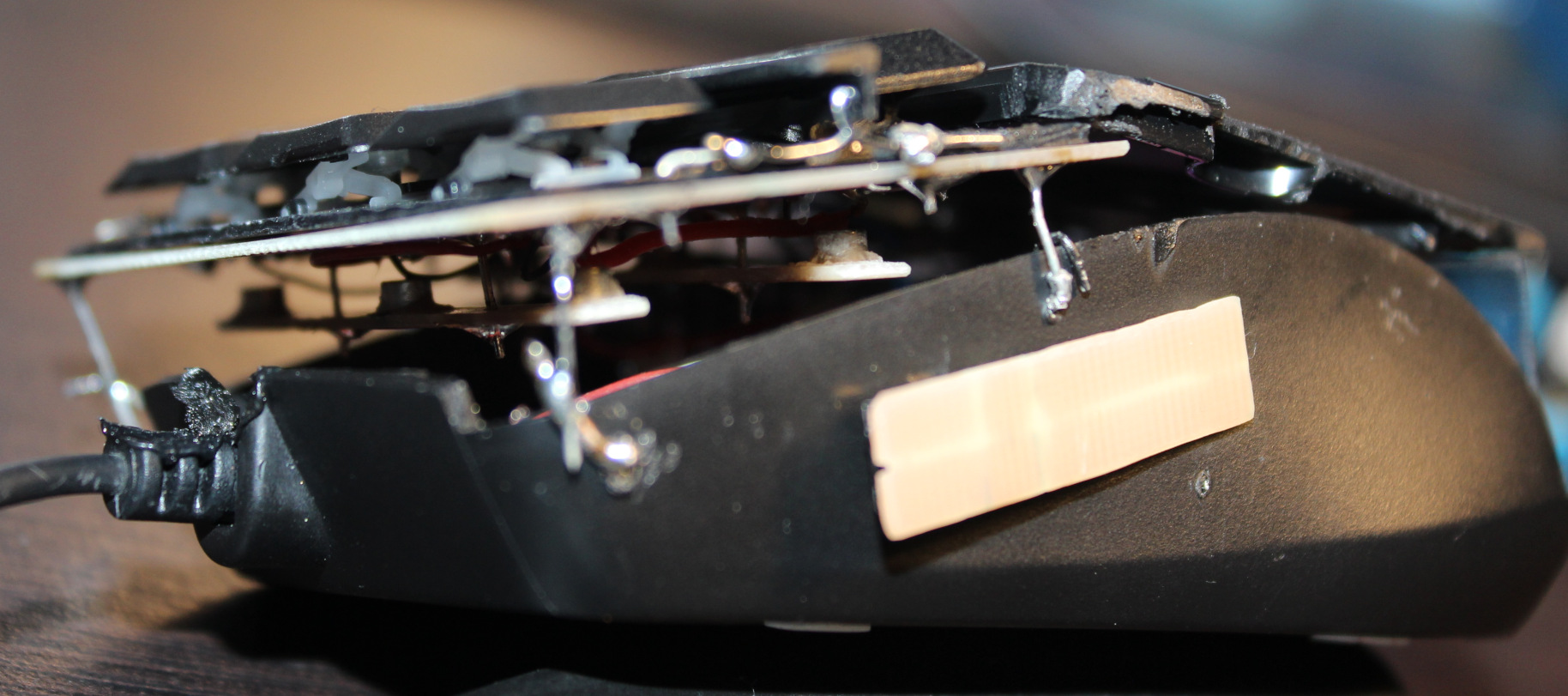
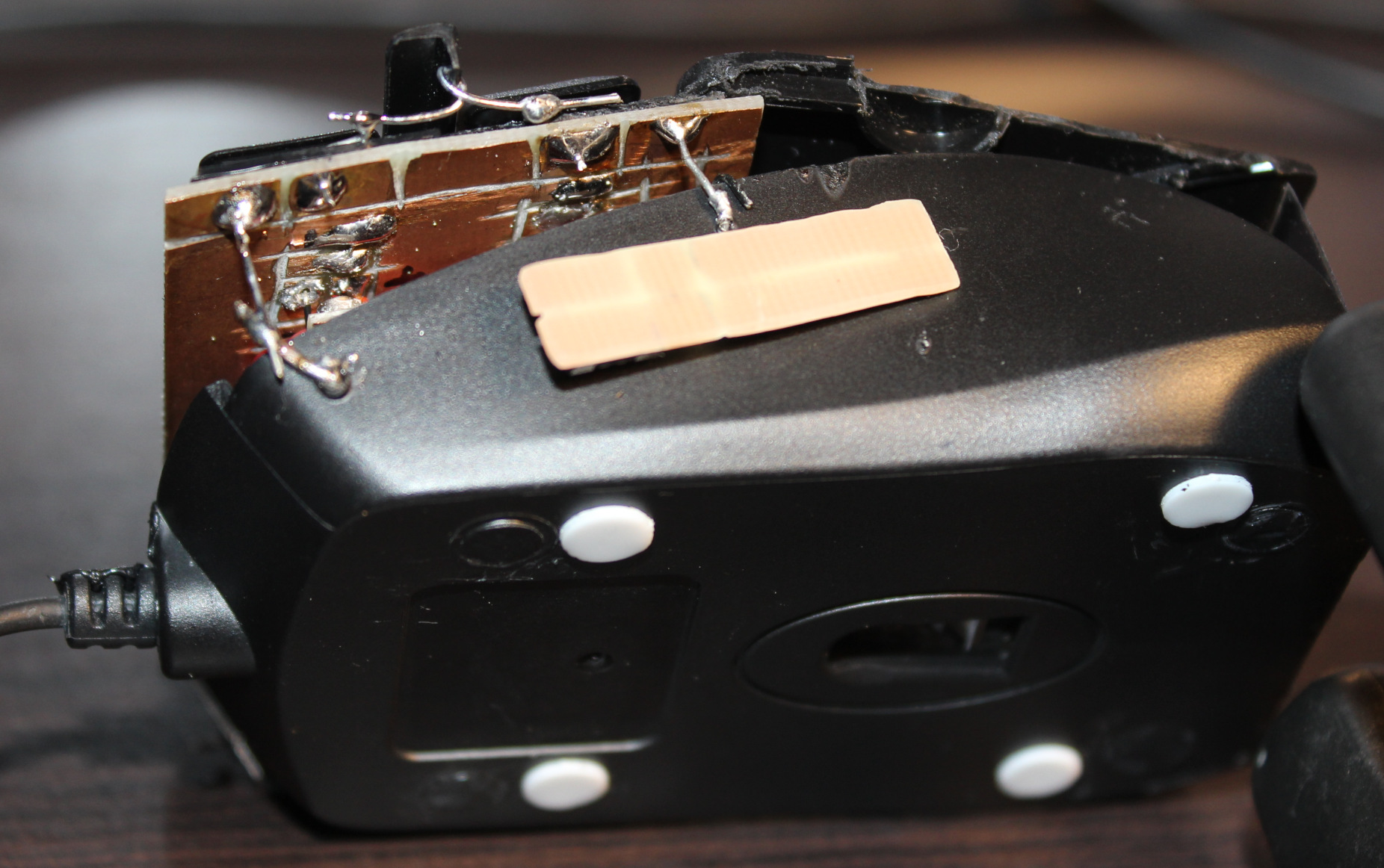
📷Gallery
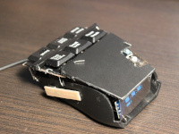
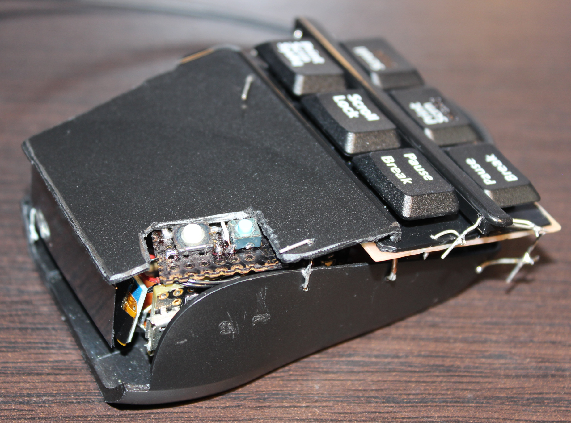
Pictures: outside, then inside, weights, keys. Later pictures show earlier versions, work in progress. Video here.
⌛Conclusions
Well, it surely is hard to get used to using it. I mean e.g. moving my hand from keyboard to mouse I can’t touch it or place fingers on these new keys, because that would already press them. That’s why this black plastic bar in middle and plastic cover are crucial, it’s the best first place to touch and rest fingers on it. So it will take a while. But I don’t want to use my old mouse already. It was nearby for a day and then vanished.
It was a good project for me. It also took me a longer while to figure it out and finish. I also wanted it done first before going after making a whole PC keyboard (100 not 6 keys) with such sensors. Probably my other design though, PCB made keys not this commercial scissor key crap.
I’m pretty sure anyone using just a default keyboard and mouse (with stupid 50 gram switches or even mechanical ones, that don’t go below 30 g I think), would likely go nuts with this mouse.
Would I recommend it? No. Unless you know for sure you’re after the lowest actuation force in keys. And that could be the case if you have an injury that makes it hurt to press the default (and so stupid) keys. As for me, I want to avoid injuries and fatigue (from using way too old, ancient switches and keys continued just for profits). That’s why I use it.
It is a joy to use even if tricky (you can’t touch this🎵) and a relief, less tiring when repeatedly. It was way to many times of me pressing the freaking mouse wheel (instead of an extra button) or even tedious scrolling. Instead I got a touch-key (for middle mouse), same like all other 6 now. Also keys to touch and hold, when I want to scroll mouse, not turn wheel repeatedly like a knob or something. I can even touch the Left button on mouse nearby with my smallest finger if needed. Lastly the “lift off” button on side is honestly like a must for each mouse. I just need to move it closer for thumb.
The mouse weighs about 48 gram now, less than my previous half of old Logitech G5 which was 62 gram (after cutting off, visible on right of picture here), so it’s also better for me. I have plans for G5 to also rework it same way. I already removed lots and checked that 25 gram is the minimum working stuff, that’d need my keys and other stuff.
There is also one thing I didn’t do: making it more ergonomic, e.g. having tilted keys at some angle. Well that’s for future project or update.
DIY
Lastly, and obviously this thing ain’t pretty. Was never a goal for me. It rather screams DIY. And it’s IMHO the only solution, not anything commercial. With DIY I got parts reused, I can fix, adjust or modify it later, etc. I set the budget (or price). It gives freedom and low cost. It promotes learning, not addiction to buying (consumerism). And most importantly for me: it makes it possible to have stuff that isn’t commercially available, and probably won’t. Crucial everyday useful things and software. I recently found this channel (mainly DIY RC toys) very inspiring and enlightening. There are plenty of DIY projects now e.g. on hackaday.
The project doesn’t require 3D printing or company making PCBs. Surely it could. But for me a 3D printer seems nowadays like a too popular, way too expensive tool, or toy even. And so many projects (e.g. here) just looking like a commercial for 3D printing. But yeah other times like a quick way of sharing your design with others.
I did PCBs just with my small drill, used with a dremel diamond cutting disc. I use it for cutting PCBs and for removing/trimming copper. This way was cheapest, I didn’t need to pay any company, and I had all stuff already at home. Of course if I had to do 3 or more mice like this, I’d go the alternative way.
This is a clock / weather station. It was a small project, that took about 1.5 weeks. It uses Esp32 board with LCD display, RTC module, and has few sensors.
✍️Motivation
I needed a well made clock, just to show time, date, temperatures inside and outside and humidity in our kitchen. Naturally I had to make it myself as no such thing existed. Every commercial product has something annoying or done poorly, which you can’t really change. I already had a few Esp32 boards waiting, and I wanted to do something useful with them too.
Until now we had:
A small, battery powered, old type LCD (black & white) clock for time, date, temperature and humidity. Was okay, but is now in other room. Even if digits are bigger, they are less visible, since there is not back light and its viewing angles are low, also depending on coming light direction.
As for temperature outside, I just put a separate, odd thing hanging on window. Was from a PC case and just using a thermocouple (which even didn’t detect below -8°C, but sadly due to climate change it’s less likely to see such temperatures here).
A timer with big digits on old b&w LCD. Have to press e.g. 30 times for 30 minutes, also it beeps on ever key press, which is seriously annoying. We still use it on fridge. But I intend to replace it with my own creation someday too.
An almost good weather station. Still old b&w LCD, big but not really that visible. It measured pressure too, strangely odd low values, IDK why. But all that drained way too much power. OFC producers want you to get addicted to buying freaking batteries (yeah.. cannot stop the battery and without vocals🎶). So the first thing I did was giving it a new 3V power supply, from nearest source our old kitchen HiFi . It was supposed to get the current time from that DCF radio signal, and I remember it had worked at first. But since years it didn’t and it always p!ssed me off when there was no power and I had to input time and date manually with stupid buttons.
Last thing I’ll mention here is that each device should have and remember its settings after power off (or battery removed). E.g. our freaking microwave oven forgets its custom programs.
Thus doing things yourself (DIY) is key here. It fixes all of the above issues and leaves room for future ideas or improvements. For such small electronic devices it has become very easy (and cheap) in recent years. I’ve seen plenty of websites with countless projects, some have a complete guide (like for kids even) with image for wires to connect, full sources with explanation, etc.
I think the key for my project with such LCD was finding a library (FabGL) that sends using SPI and DMA. First I found a video showing it works well, then sources here, and a good reference on how and what it can draw. It was the same story as with my keyboard which has the same LCD. It is most important to draw as fast as possible. Those aren’t tiny projects with small OLED displays on I2C which could use those Adafruit libraries.
There can also be numerous ideas for new features for future. E.g. since Esp32 has WiFi, it could read weather forecast from internet (if I had WiFi set up at home).
⚙️IDEs
I was pressed on time, since I wanted a new clock, not spending long time on setting up proper IDE to develop. So I just used that abomination of an IDE called Arduino “IDE” 2 (1 was even way worse) for build & upload and edited sources in VSCodium with my theme and setup.
There are definitely few alternatives for Arduino IDE (which is easiest to set up and get working, but nothing else):
PlatformIO, sadly only for VSCode (I‘m not okay with being MS slave). There seems to be a way for VSCodium here, I didn’t try it.
Sloeber, is based on Eclipse IDE. E.g. video of it. (I dislike Java and Eclipse too). It worked for me, but I’m not sure if all needed libraries are there too, FabGL didn’t find SPI.h for me, probably needs even more time to set up right.
ESP IDF, the official way for Espressif MCUs like Esp32, also a video for starting. Seems like it needs building from sources on Linux, so I also didn’t try yet.
📂Sources
Sources are here. I was editing code in VSCodium, then building and uploading using the worst Arduino IDE 2.
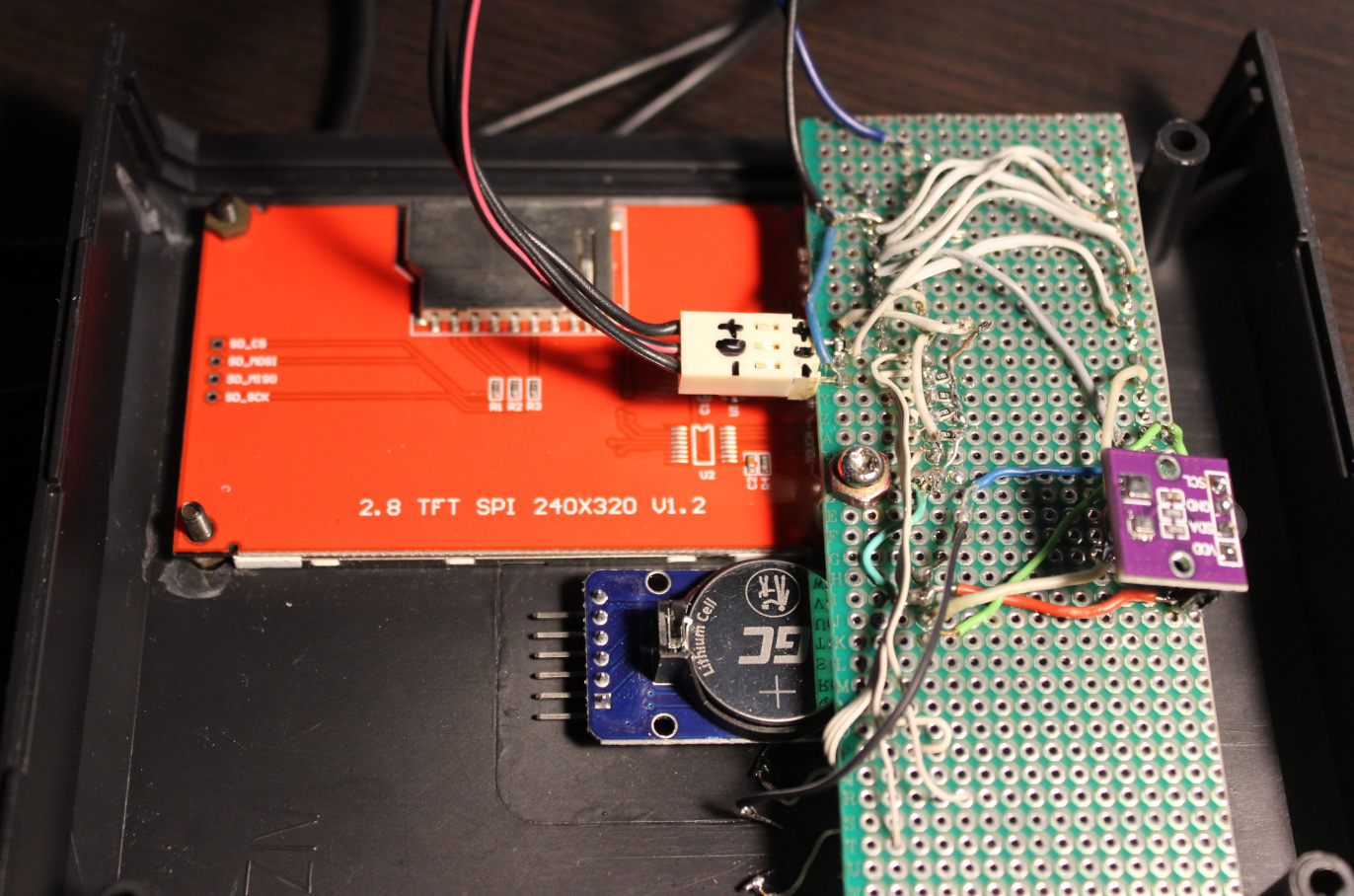
📊Features
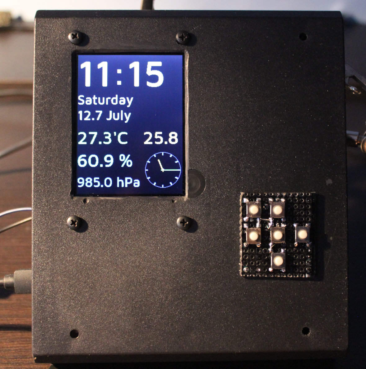
MCU: ESP32 dev module – older Esp-Wroom-32, has 36 pins (pinout), not really important which
Display: LCD TFT ILI9341 – vertical 240 x 320, 1 pin with PWM for brightness LED
RTC: DS3231 – for time and date, with CR2032 battery (used when power goes out)
Sensors:
AHT20 – temperature and humidity,
DS18B20 – external temperature,
BMP280 – pressure
Keyboard with 6 keys: up, down, left/dec-, right/inc+, enter, back
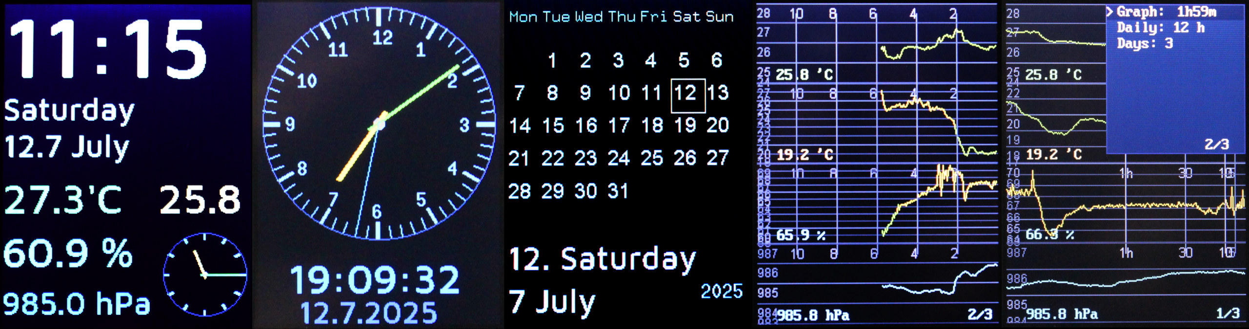
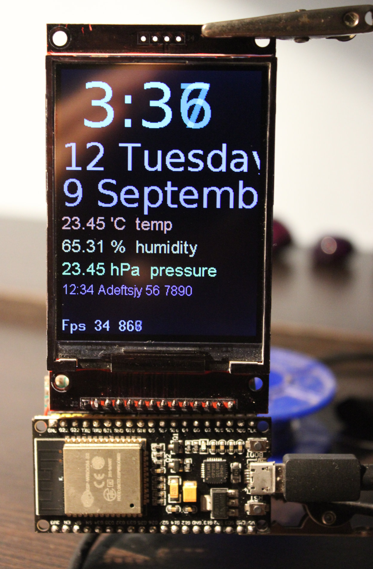
4 View pages showing:
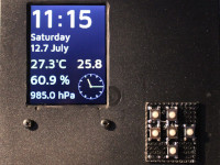
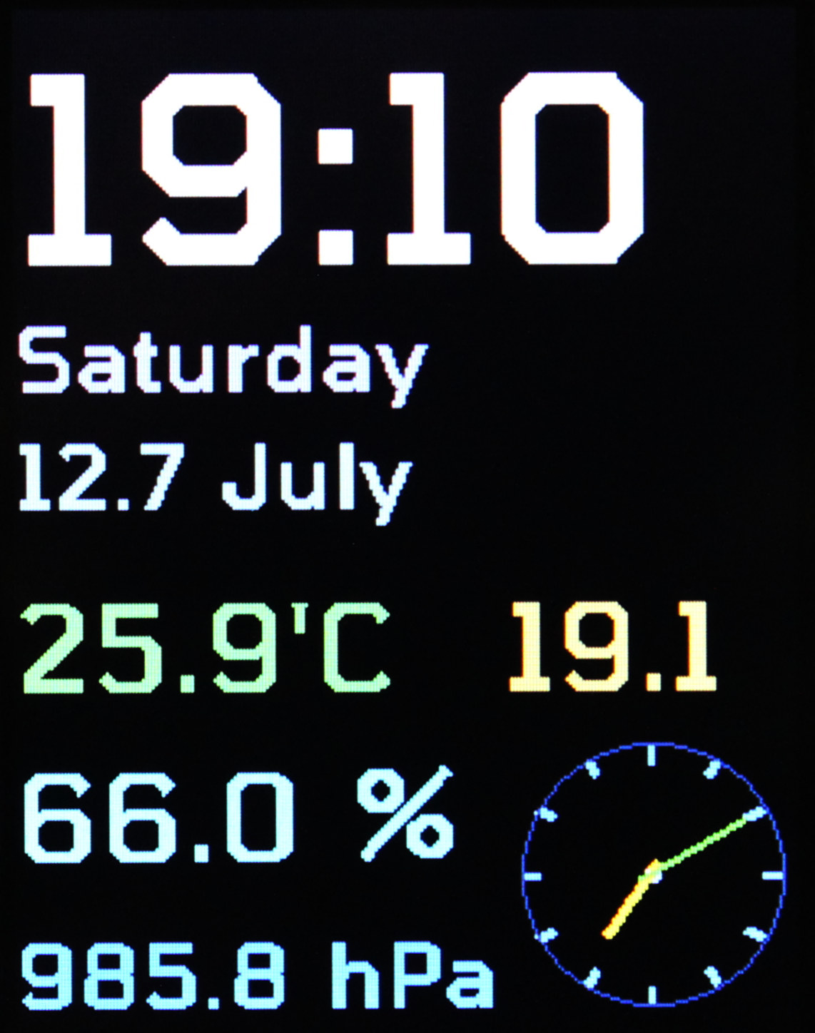
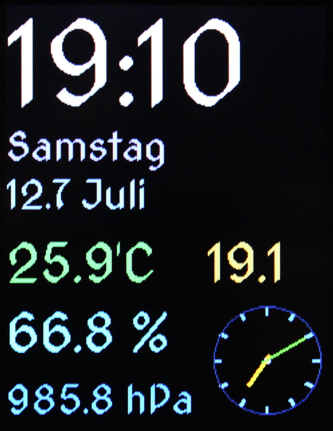
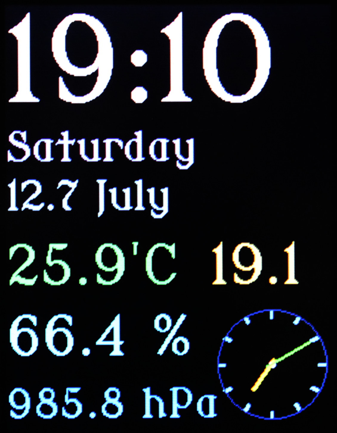
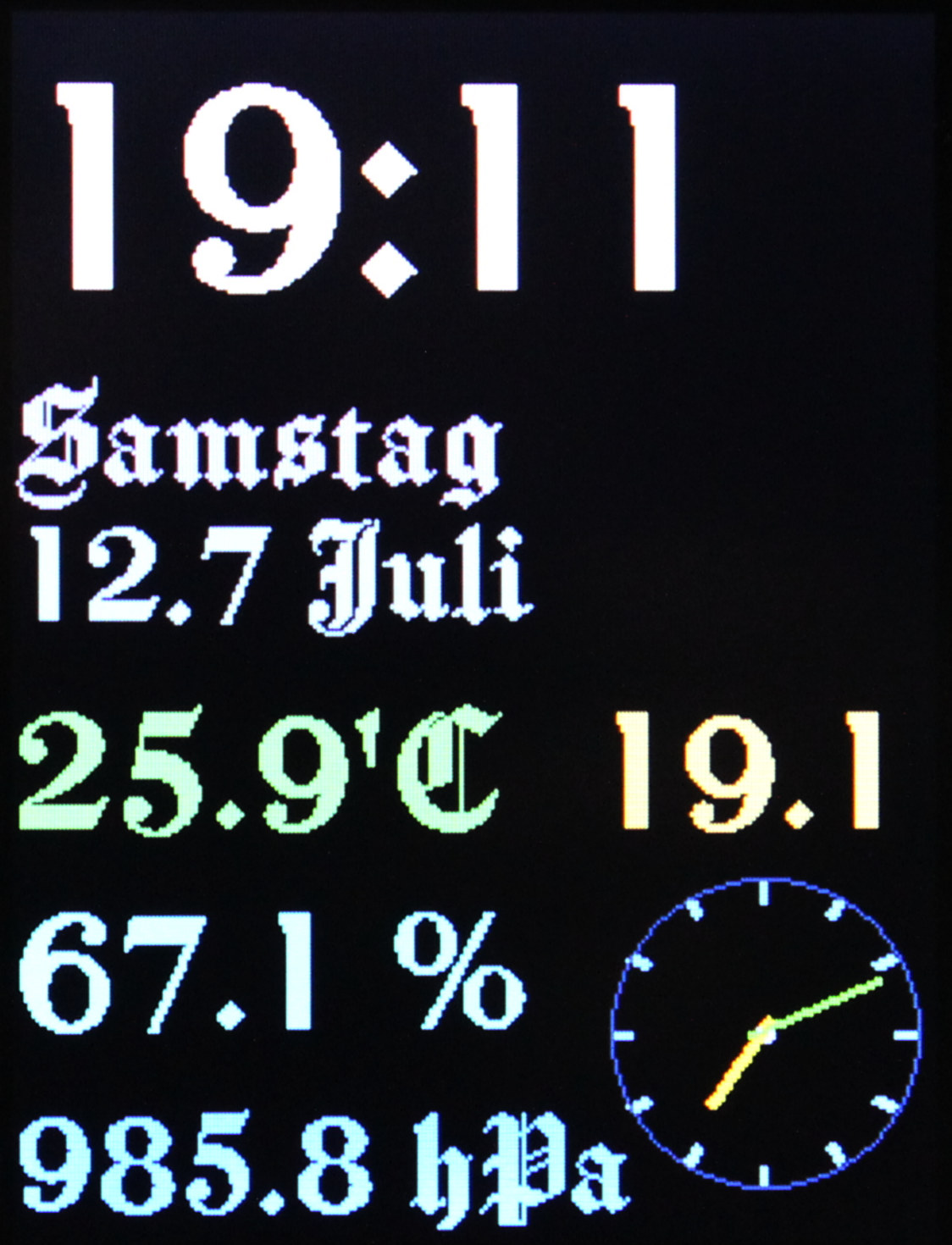
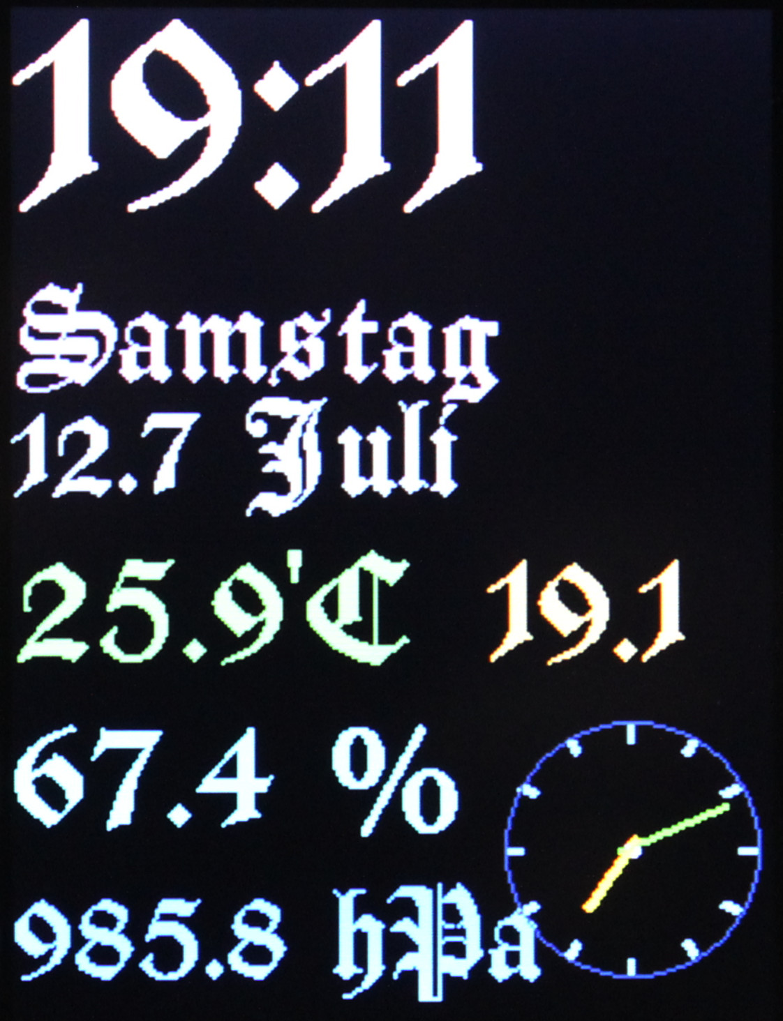
digital clock with date and 4 sensor values: temperature inside °C, outside °C, humidity %, pressure hPa
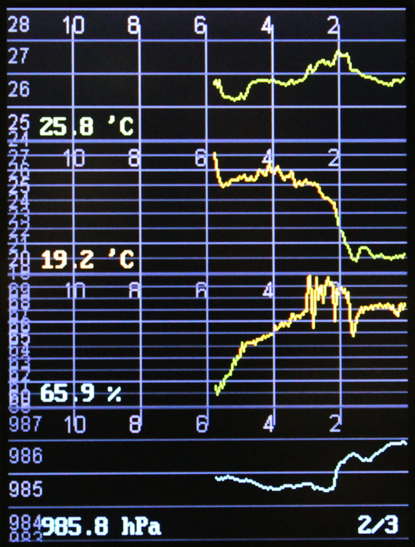
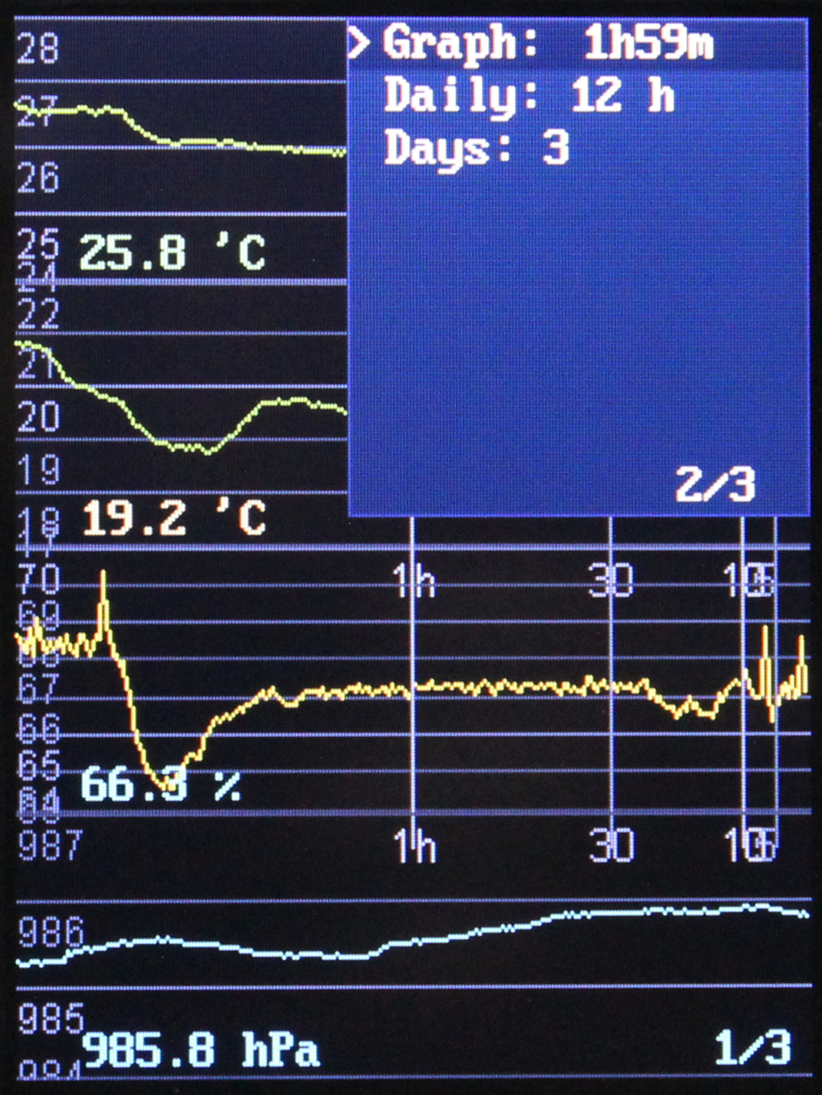
📉 4 sensor graphs: in one of 3 views: hourly, daily, days (time lengths for these are in options)
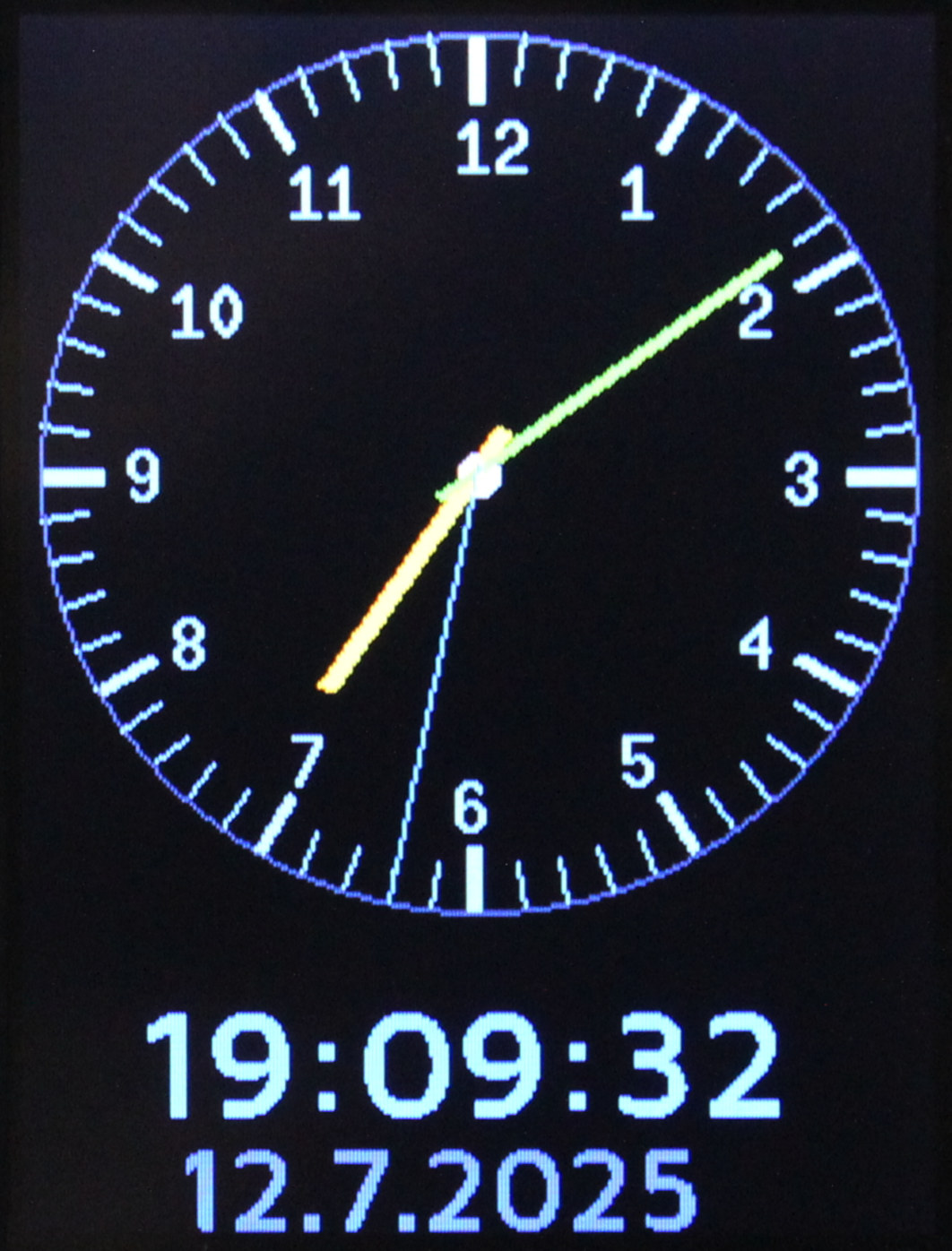
🕑 analog clock with date
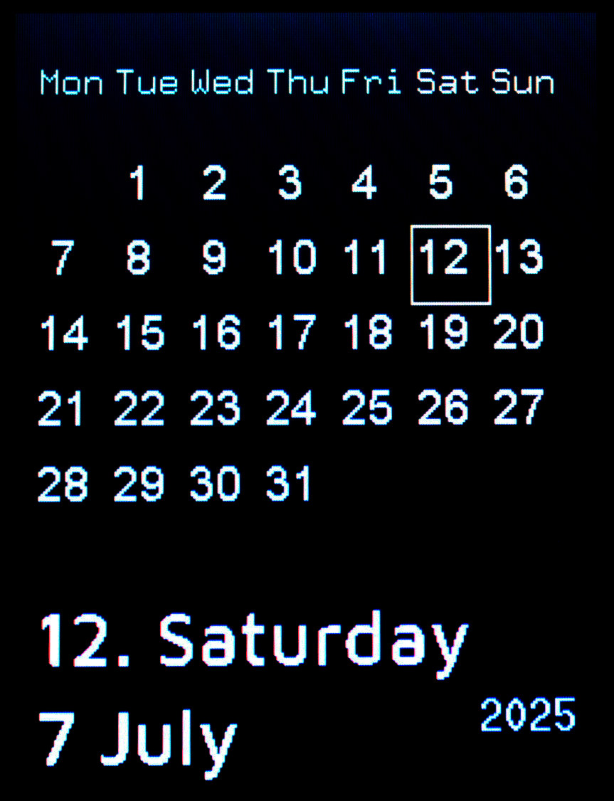
📅 calendar month view
7 different fonts (styles), 3 sizes searched for OFL licensed fonts on this website. Then used FabGL’s tool to generate .h file from font for each needed size. Lastly wrote a helper .py script that does this for all .ttf I have (I also put them in repo)
simple Gui with options (on 3 pages), config is stored using EEPROM
➡️Conclusions
So far it seems great. I don’t see much I’d change, and when I eventually will need to, I can just unmount it and take to develop its code and change anything really. It’s what’s missing in every commercial project. Only open hardware with open software allows this. Turns out Esp32 (at 240 MHz) can handle such 320 x 240 display very well. When using SPI at 80 MHz it does draw about 35 (with texts) to 41 Fps (when almost empty). I am already using same display in my keyboard with Teensy 4 which is even faster (600 MHz) but way more expensive, it does always 45 Fps (at 60 MHz SPI, could do 60 Fps at 80 but that failed for me). Esp32 for me really is best in terms of performance and cost now. And since I managed to finally do something using it, this will make it easier for future projects also using it.
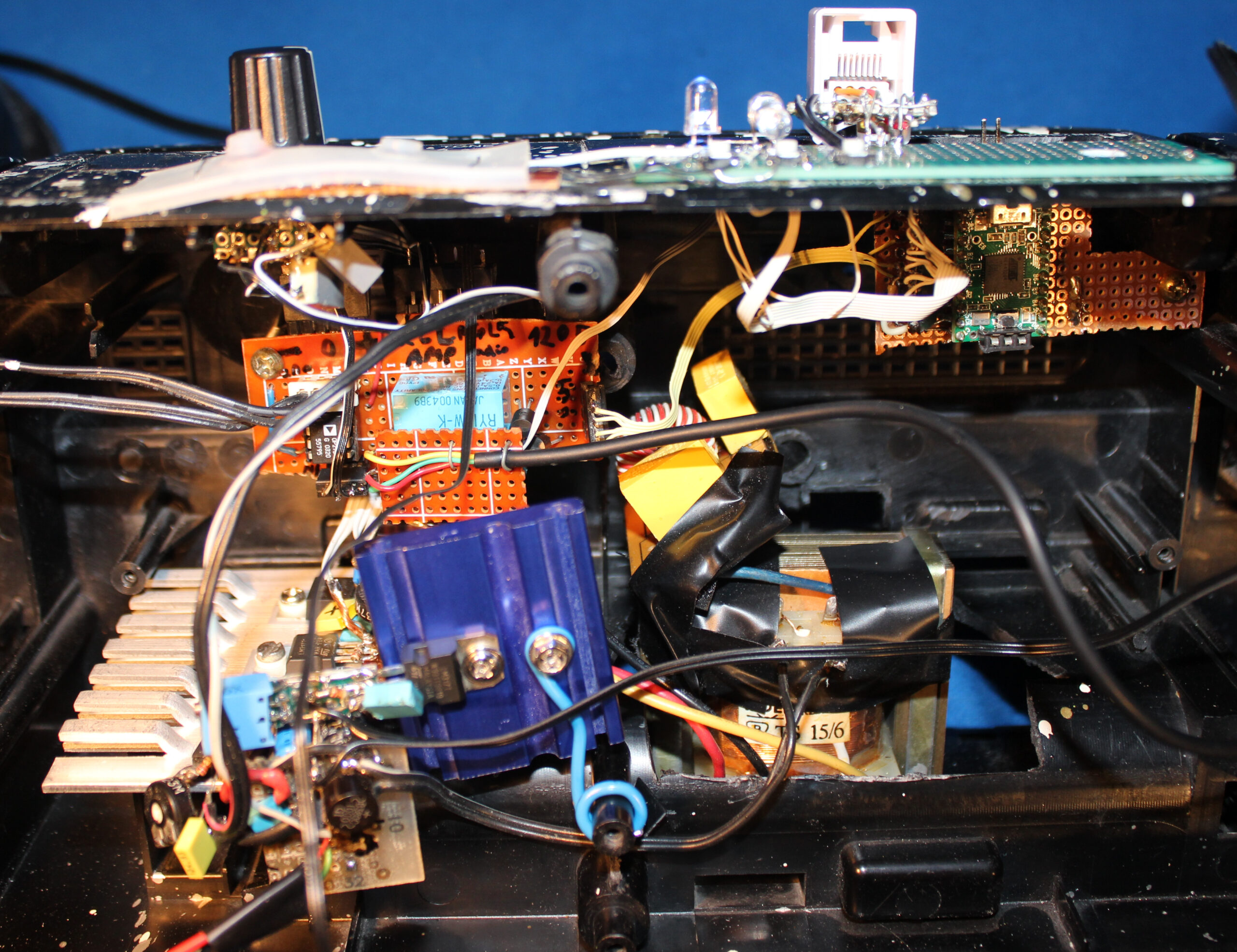
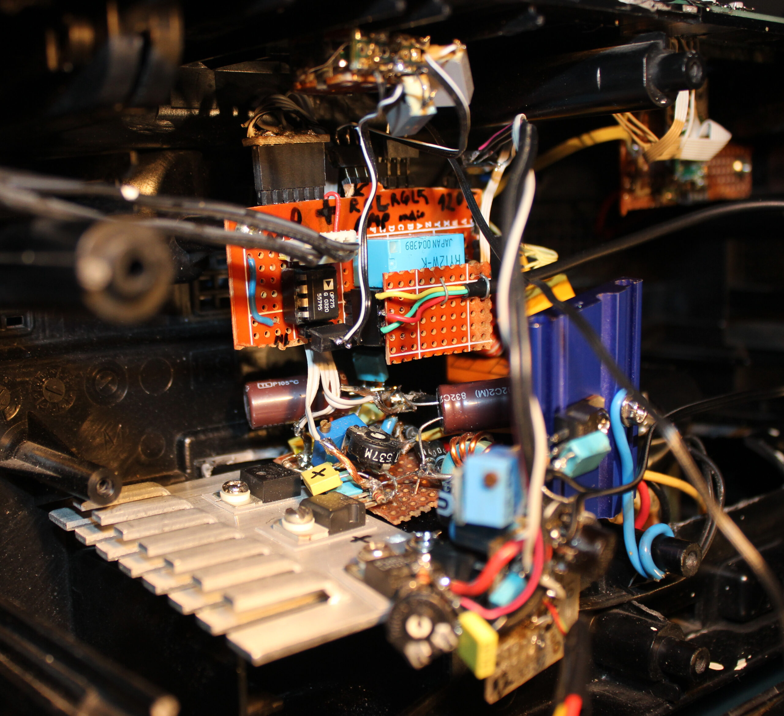
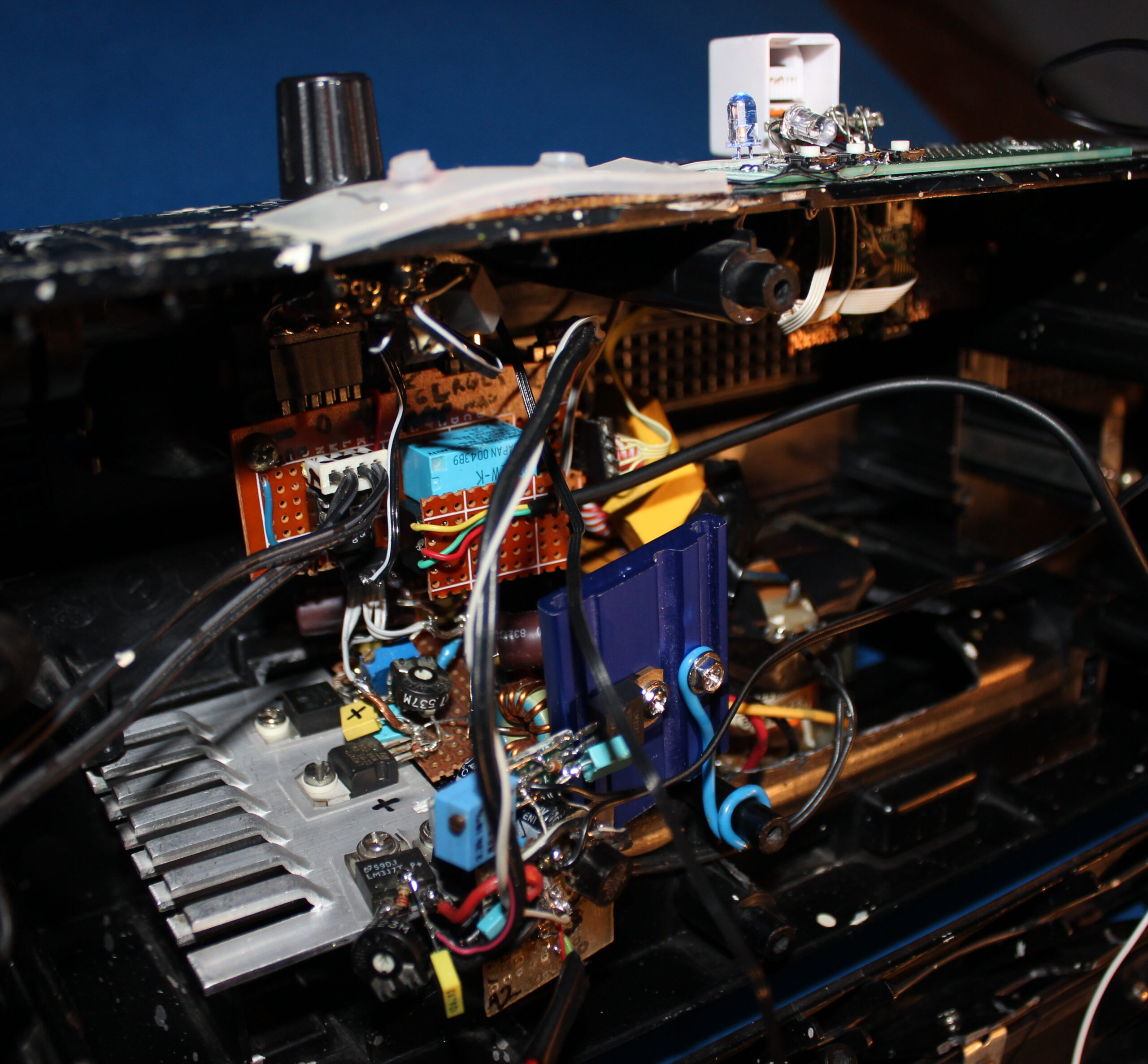
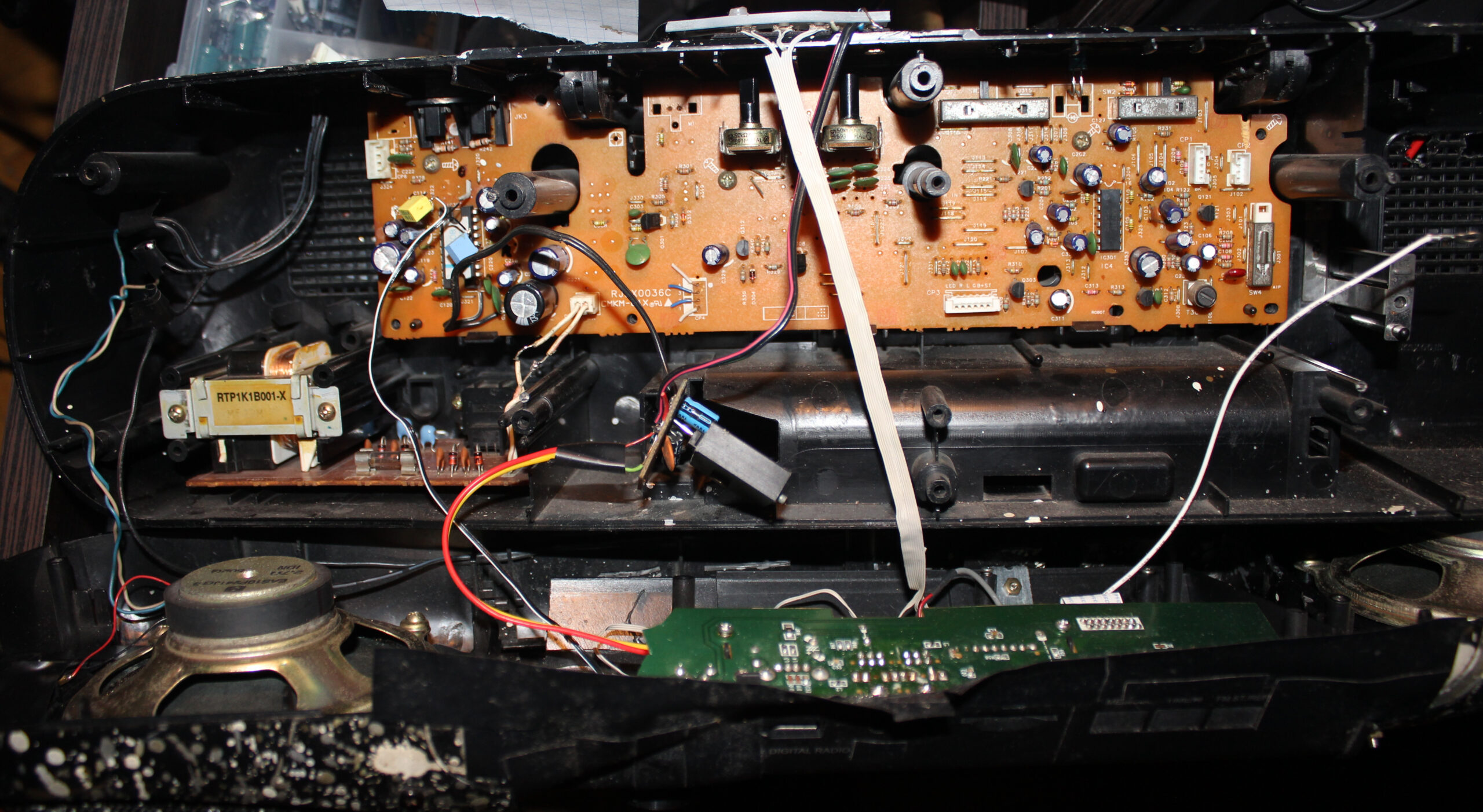
This is a continuation of my previous kitchen HiFi modding. Now with replaced electronics for power supply, amplifier and input selectors. Only radio and case stayed the same. So roughly half is made by me.
✍️Motivation
Previously there was here an ancient old power amp chip LA4108, from around 1995 or so when this HiFi was build, with 2 cassette decks. This amp was way too powerful and not quality enough for our times. Since I didn’t need much power, I just remade it with a very simple op amp amplifier, feeding speakers. I also wanted a holder to put my old audio player in place instead of just lying flat and hardly seeing its LCD. Lastly my mother found it hard to see what to press for radio and lost the volume knob behind our kitchen stuff since I moved it on side.
📊Features
Op-amp amplifier feeding 2.7 Ω speakers through 47 Ω resistors. I still had OP275 lying around since like 2002 so I used it. Well it could be NE5532 or anything really. I didn’t bother with any transistors (class AB or A) at all to boost current or more power op-amps, because it was enough and we don’t need to hear it too loud 🔉🤫.
Selecting 1 of 3 audio inputs from: FM radio, player (Sansa Fuze+ with Rockbox firmware), and external audio cable (going from my room to kitchen, analog but through Ethernet cable). This is done using a MCU (worst for today Teensy 2.0, only because I have bought it long ago when I started and wanted to use it for any purpose finally, it’s ancient 8bit and 5V too, while I moved to 3.3V in my keyboards and all). Code was like just 50 lines, 3 buttons, 2 outputs for old 12V stereo relays, and 3 outputs for LEDs to show which input is selected to play.
Power supply for player 4.1V not from battery anymore, slightly with noise due to this. Op amp uses +-16 V from 2 regulators LM317 and LM337 from a 15W transformer (could be less, but it’s what I got since years waiting, not used). Another with 12V for relays, and 5V for MCU. So yeah kind of nuts 5 voltage regulators here. It’s likely the reason it takes 3.5W from 220V wall, already doing nothing and about 5W doing something.
⌛Conclusions
Well half of my conclusions are already in my previous project for this HiFi back there. I.e. no reason at all to buy new stuff, better to modify this over 20 year old classic, especially after I painted it so funny. It was also working so best to extend it further and make it better for me.
So far I can say it is a joy to use and really good audio quality for me. I didn’t hear any noise, especially not like before. I hope it will last for few years at least, until I come up with something new I’d like to add. Or possibly get my stuff from inside and use new speakers, who knows.
One definite down side is that it took me about 5 days of holiday to do this, so it was way more than I’d like and lots of work still.
Another bad thing is that it uses 4 W power constantly, likely just because of so many voltage regulators here. I didn’t complain about this, since I got more power lost in stuff that’s constantly on in the house all the time.
But this also, eventually motivated me to rework it once again in recent project from 2026.
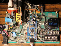
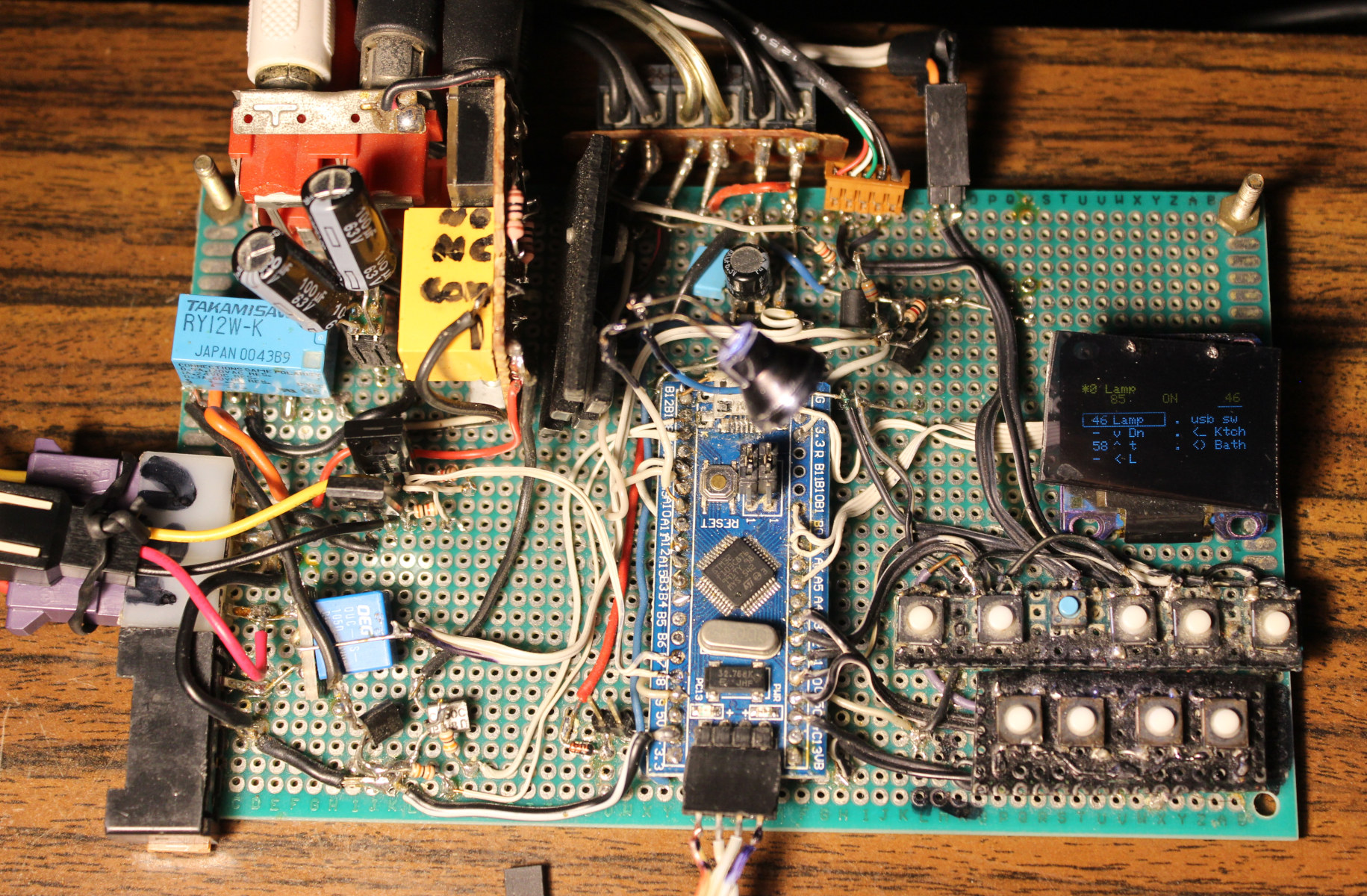
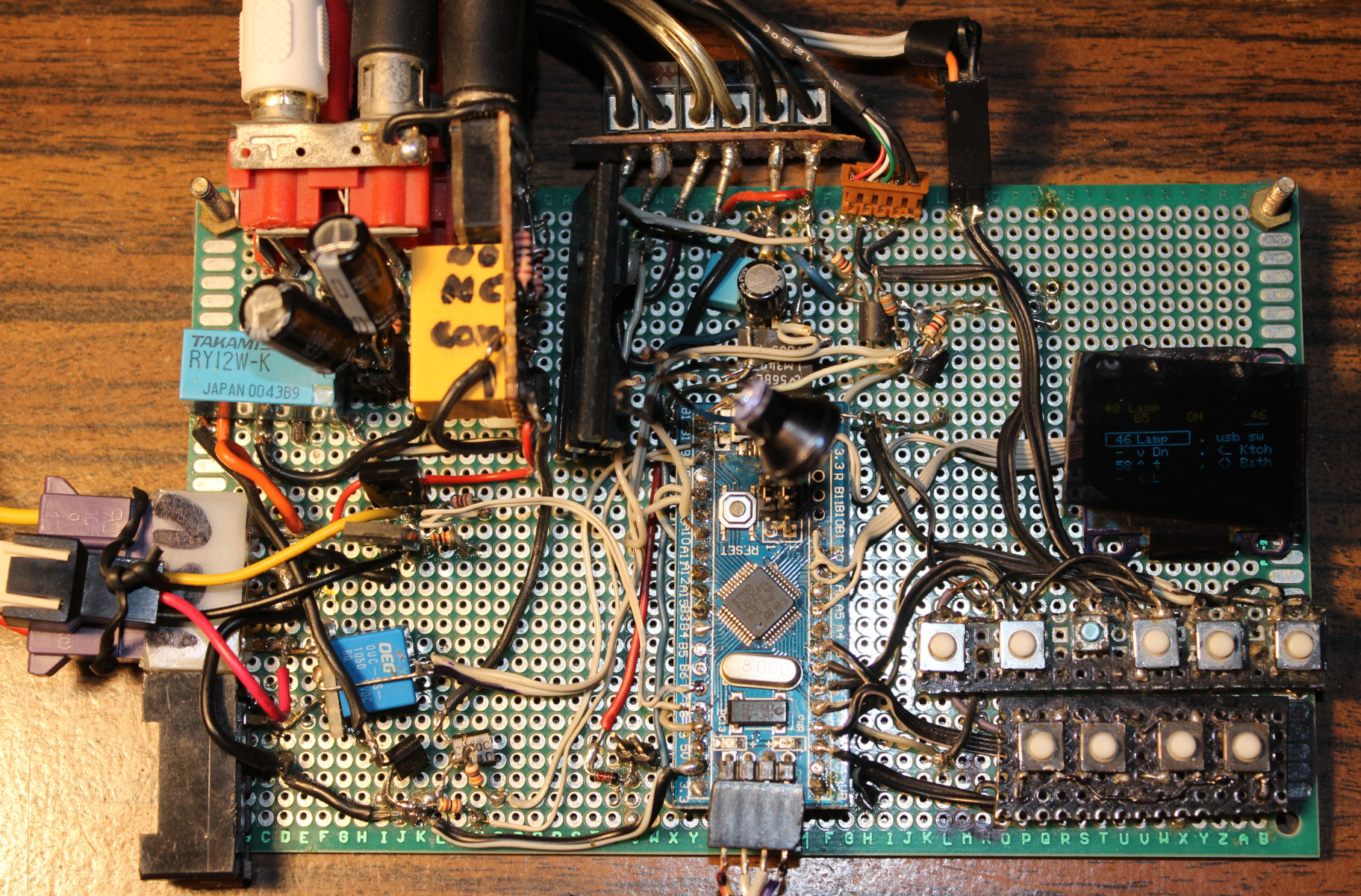
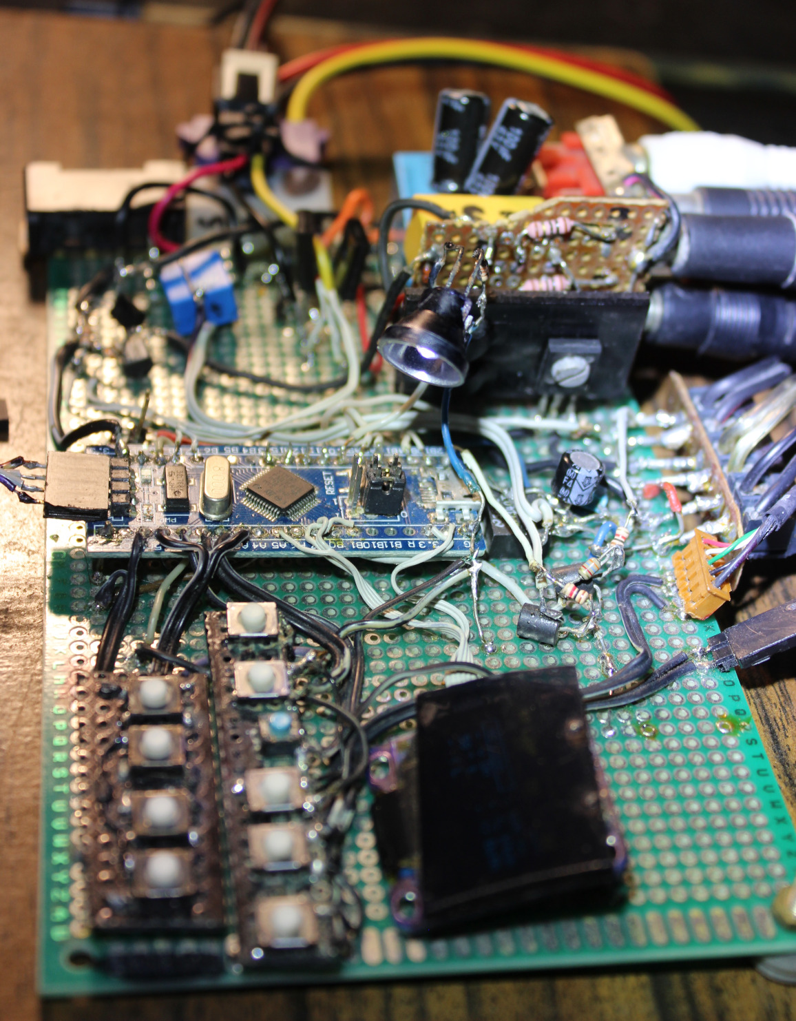
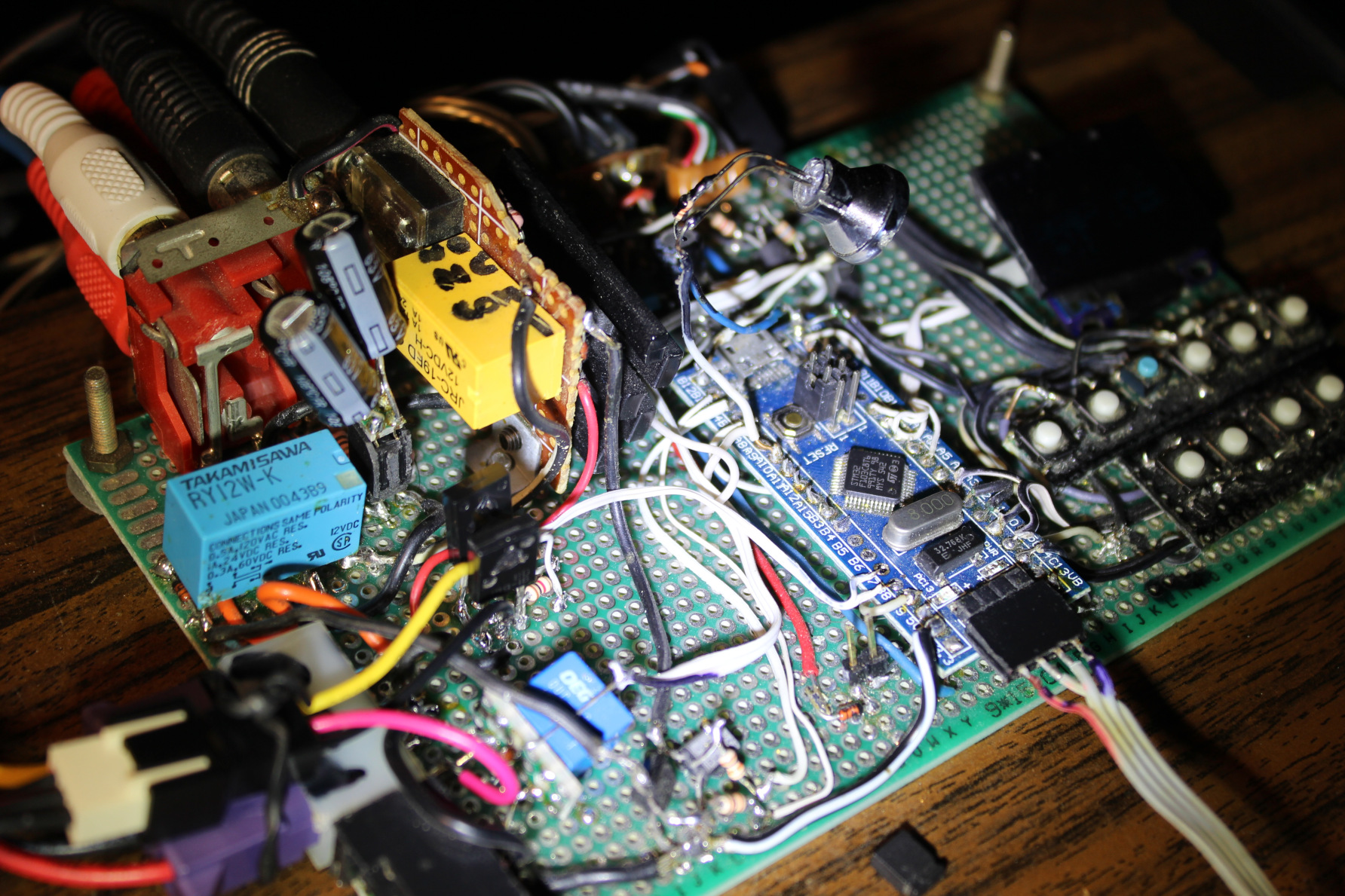
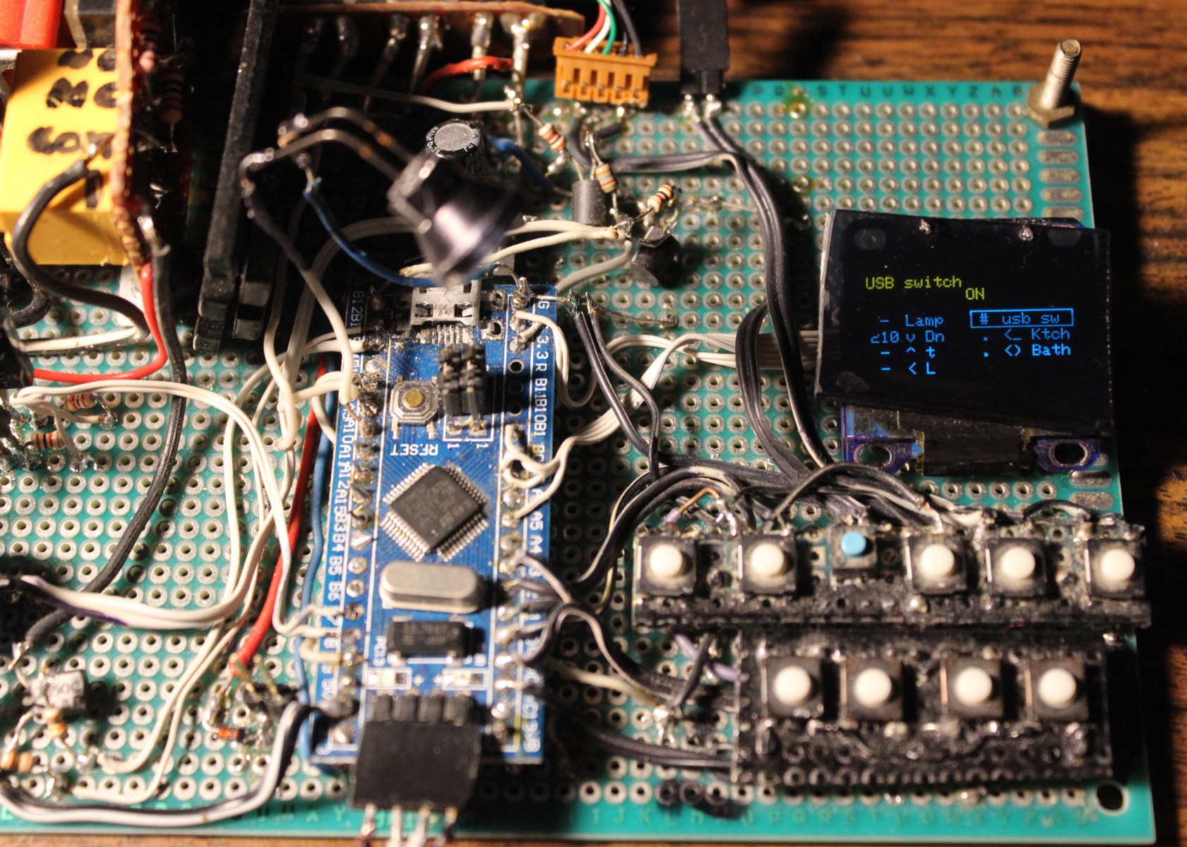
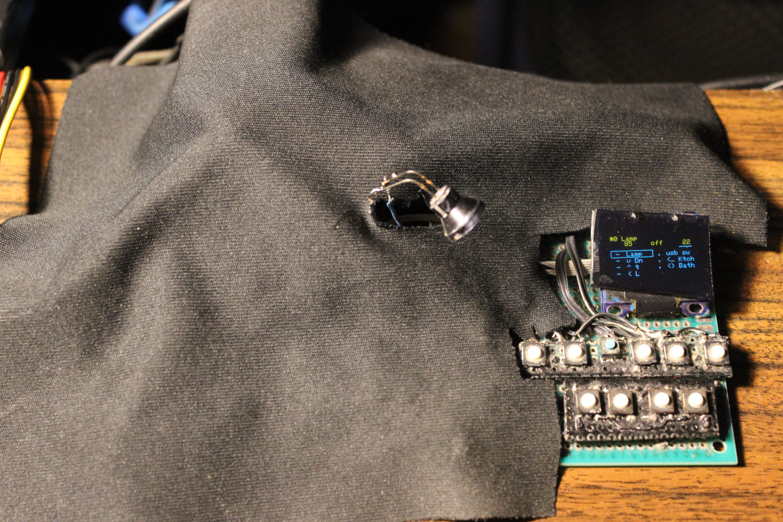
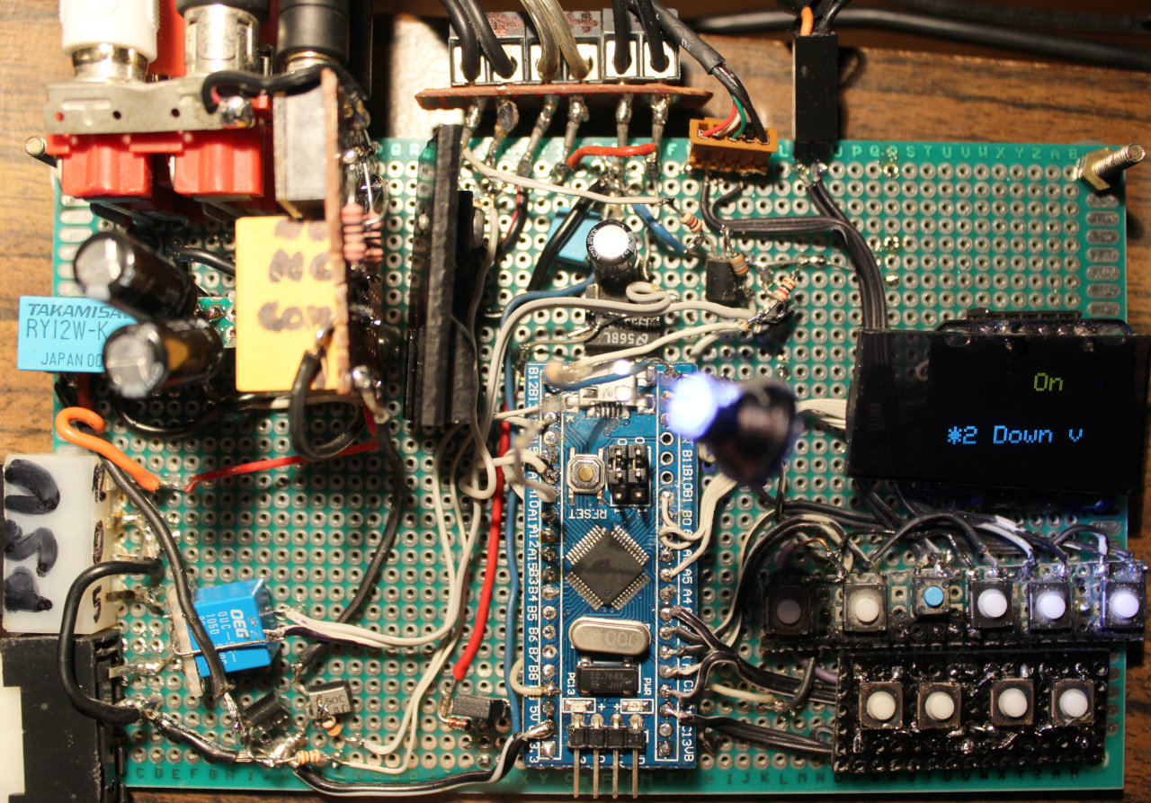
This is a tiny project, that took about 2 days in 2022. It uses the “Bluepill” MCU board with small OLED display. It has few buttons to toggle LED lights and relays for audio outputs and USB switch. In 2026 I improved Gui with menu and added LED lamp.
✍️Motivation
For many years (seems about 20) I was using just old logic chips. And it felt ancient, so I finally decided to do it with bluepill. I have a tutorial for microcontrollers here. Having a small display is nice and informative. With many inputs and outputs (pins) left, there is still room for future changes or upgrades.
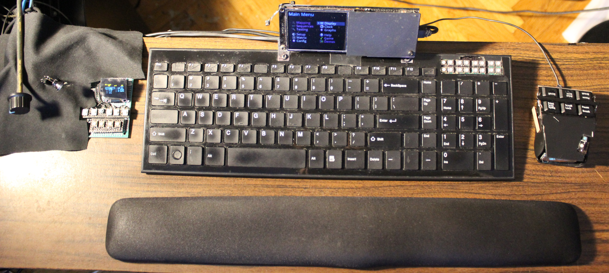
This “console” is very useful and has a place just left of my keyboard. Visible on picture📸 of my movable plank / desk with also my keyboard ⌨️KC4 and mouse 🖱️MC1. Most recent addition on very left, is the new “knob on stick” for DAC’s volume🤣. Very useful and minimal, just looks weird🤨. Better than having heavy and warm DAC here.
It has no case and likely never will. I’m just covering it with a black cloth, cut to match (picture).
📂Sources
Sources are here. Actually just using that Arduino .ino since it’s a small project.
I was editing its code in VSCodium using my own theme as usual, then quickly building and uploading using the worst Arduino IDE 1.8.19, then 2.3.2 (still very bad). Its options are way too minimal, and it still doesn’t even let choosing syntax coloring themes. The alternatives didn’t work for me, and are harder to set up. So Arduino still is the easiest to use, but not really an IDE.
📊Features
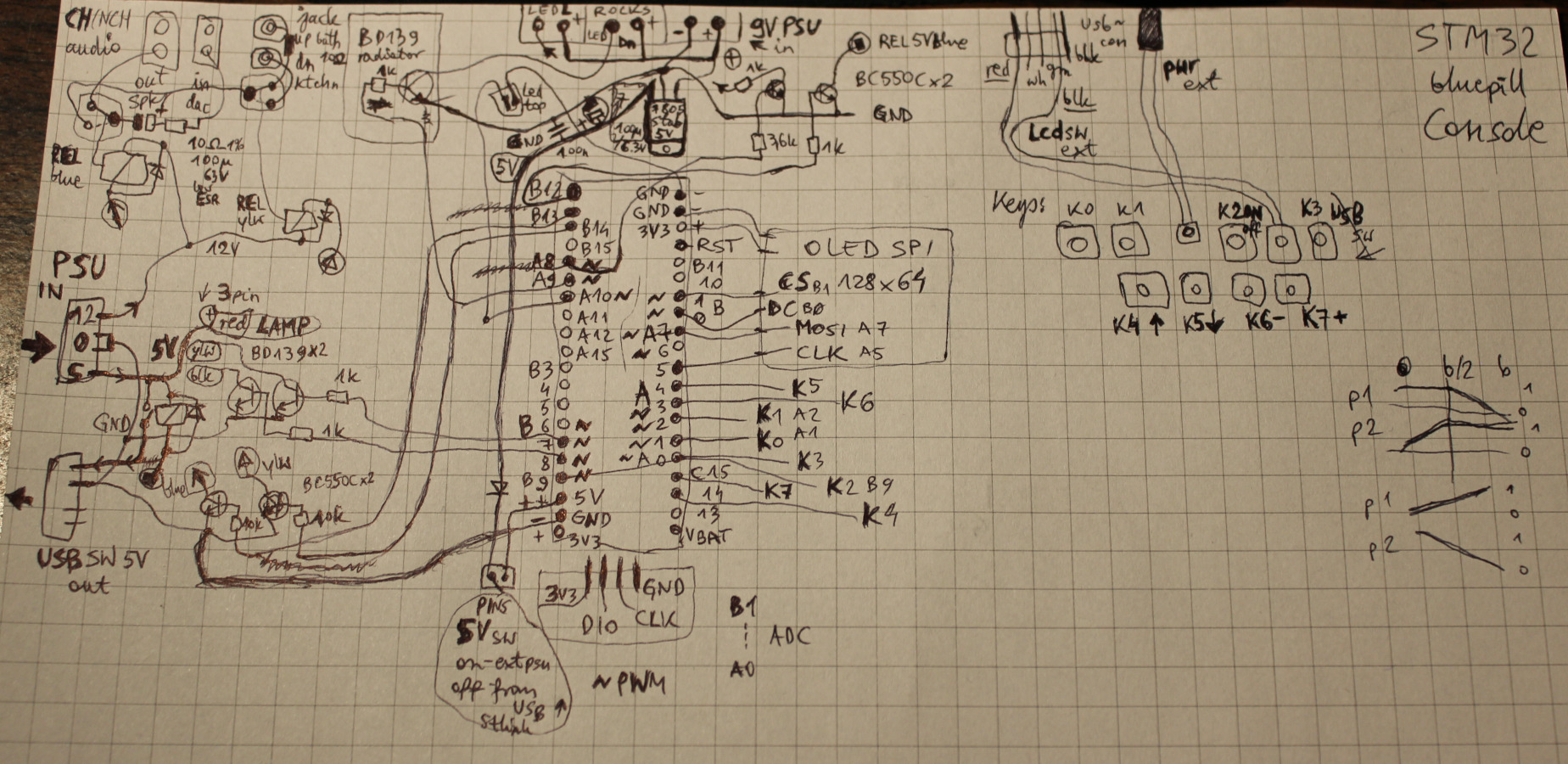
STM32F103C8T6 “Bluepill” MCU – cheap, but decent. It has many outputs (GPIO), still few left. No need for anything faster.
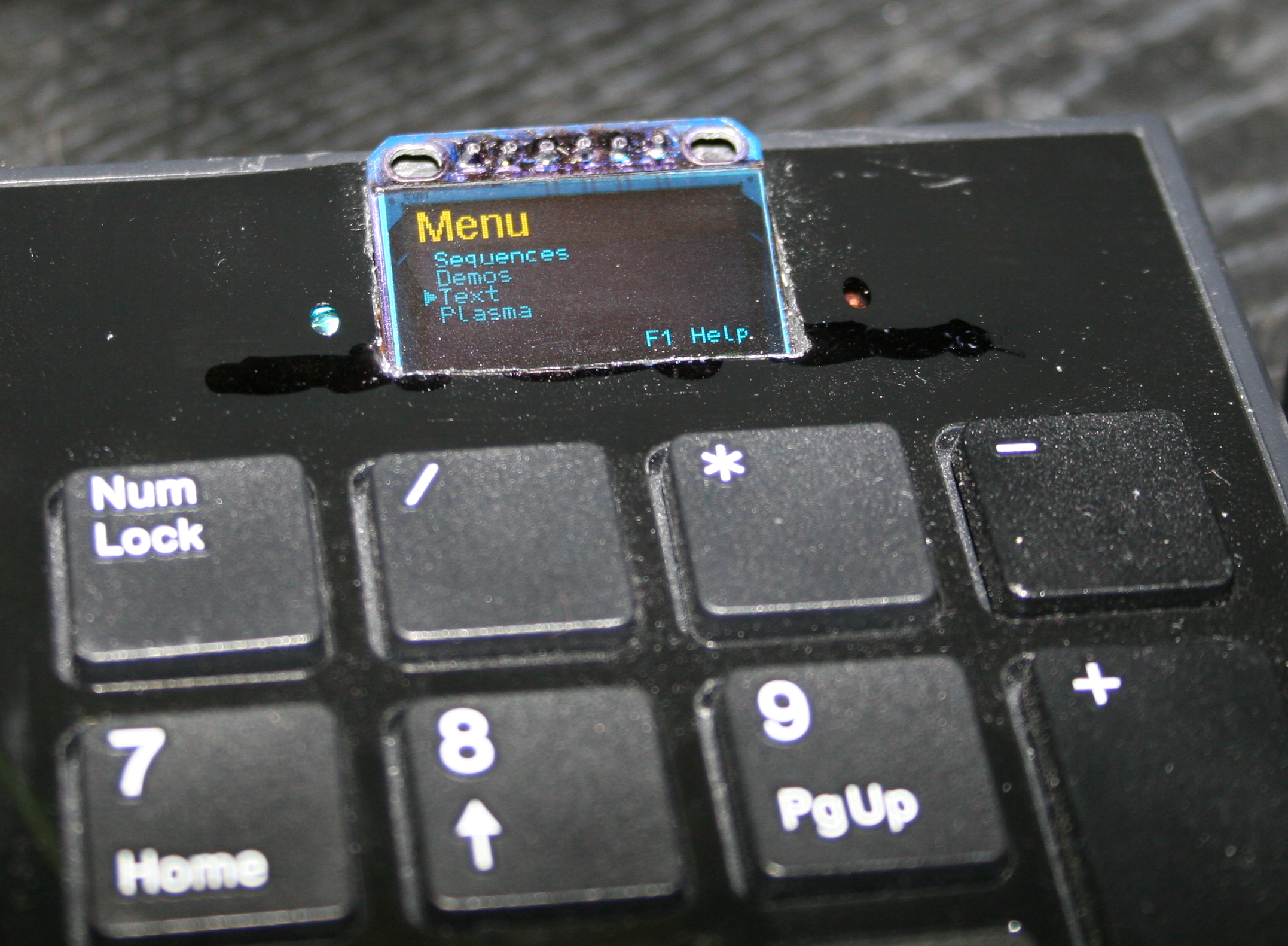
OLED display, 1 inch small, 128 x 64 mono (top yellow, rest blue, SSD1306, SPI). For Gui menu with list of all outputs, and details on top, for one selected.
Few buttons, to navigate Gui and change values. Using 8 microswitches (lightest 0,5N press force). The 8 Keys are: Up, Down in list, On/Off toggle, Dec -, Inc + value, toggle Gui auto hide, toggle mode (bright or balance for lamp), toggle all lights.
Outputs:
🛋️LED lamp (has 2 pins yellowish and blueish) with balance value to adjust between warm white and cold.
💡3 LED lights (left, down and top) – on/off and adjusting their brightness (PWM outputs).
🔉Audio DAC output to: speakers / headphones / bathroom (using 2 double relays, and 12V from PC PSU).
⌨️USB switch. A relay directs 5V from PC PSU to my own USB switch that directs 2 USB (keyboard and mouse) between either PC or laptop. The switch uses 6 relays (5V), not best, as it needs about 3W when on.
Just as a place to mount my 2 other important buttons:
LCD monitor input switch
PC power on/off
If I’m not using a 2nd PC (laptop) then LCD monitor input switch and USB switch aren’t needed.
📷Gallery
Including pictures with: rough schematic on paper, the cloth normally covering it, and its location left of my keyboard. At end also old version from 2022, very similar.
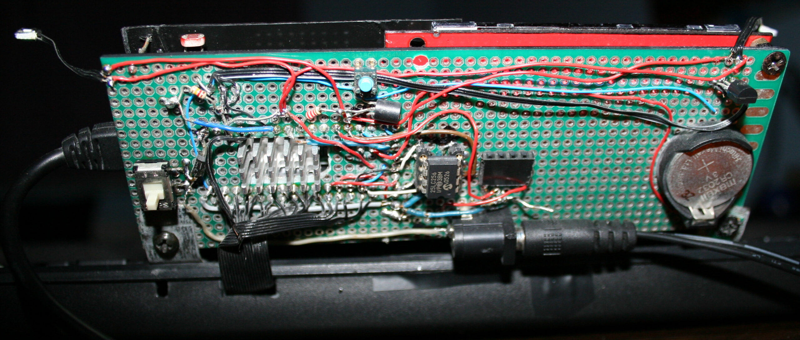
This is a nice gadget I made recently for controlling speed / power of my PC fans (all are 12cm, 12V, 3 pin, with RPM output). It has way more features than my old & basic 3 knob regulator which I used for over 15 years. And since this is open source (and I wrote it), it surely has and can have any feature (commercially unavailable, not even thought of, or way too expensive). Obviously it isn’t badly needed, that’s why I made it after so long.
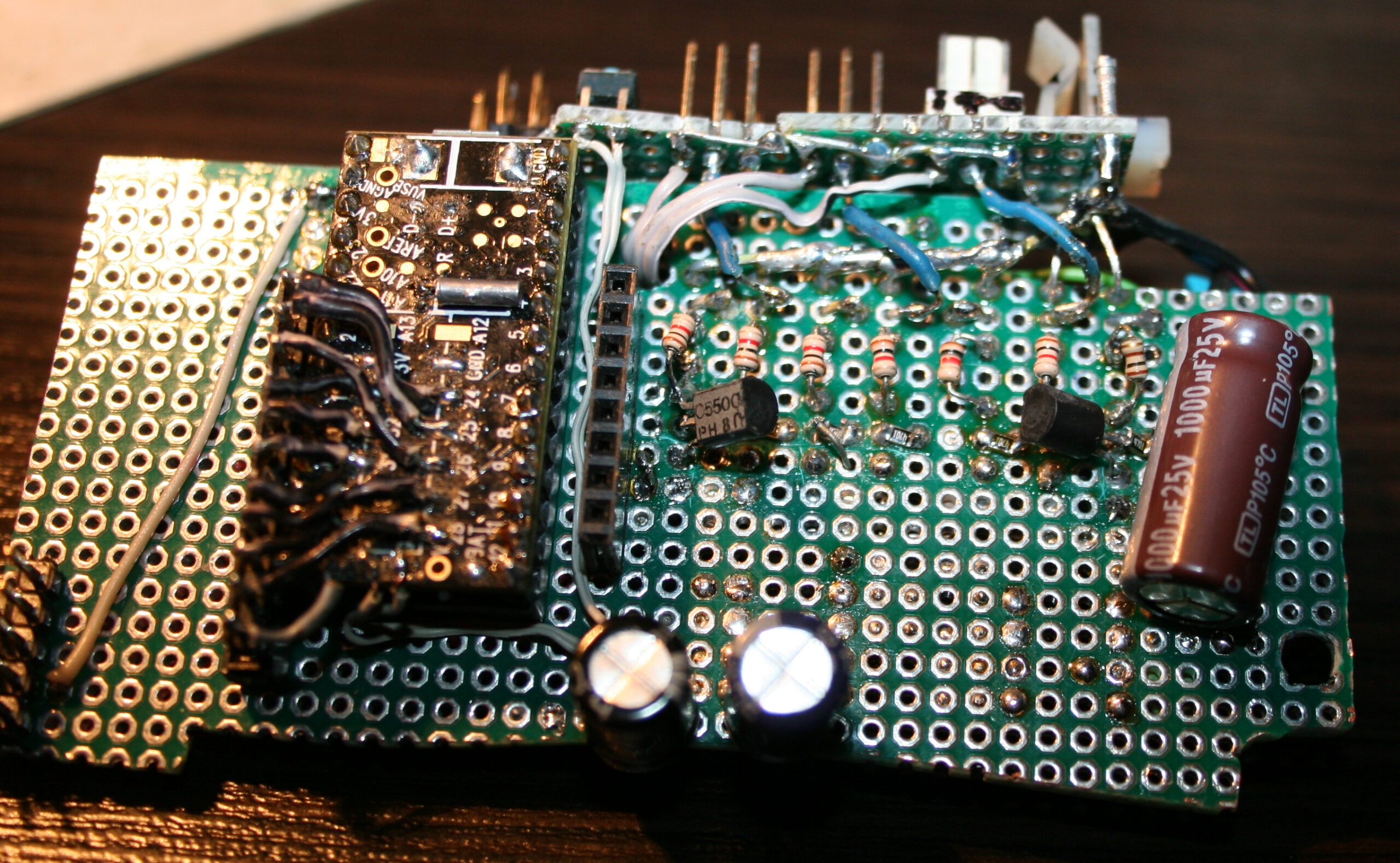
I do not recommend Teensy 3 at all. All Teensy boards are quite expensive and aren’t that needed for a fan controller. I think a bluepill or blackpill would suffice and be much cheaper. More info and detail in my MCU tutorial. I simply used Teensy 3 since I had it available, doing nothing and I had code for it from my older keyboard firmware, so it was faster to adapt it.
✍️Motivation
For many years I was using just the simplest LM317T voltage regulators with 3 knobs (for 3 fan sets).
Obviously a basic analog fan controller is very simple and extremely useful. I had 3 knobs (5k logarithmic potentiometers) with LM317T (even with no capacitors or radiators), mounted in the 3½” floppy disk bay. It was working very well for years and I could still use it. It only works for analog, not PWM fans.
I did try once a Gelid Speedtouch 6, wasn’t very cheap, and it was hopeless. Even worse, when I realized that I can make a better one myself, like usually. Additionally, after being rather finished with my keyboard features, I had some Teensy 3.2 boards left, lying around, doing nothing, simply asking to be used for something. Even better, I could use my older keyboard firmware for Teensy 3.2 and adapt it fast for this controller.
So I finally got to creating it. I called it “Fancy” from Fan C(ontroller). There was something new to learn too. I even used a cool circuit simulator to find out resistors around transistor, wasn’t exactly the real value later though.
And of course not everything went as planned.
For example: I wanted to use thermocouples for temperature which I had few of already. I tried an op-amp with differential amplifier for them and used ADC to read voltage which seemed working on breadboard. But after doing that for real (and using bigger resistor values) something didn’t work and I saw noise. So after few days trying I dropped it and just used DS18B20. They are bigger (3pin package) but have more precise measurement (at higher cost too).
Unfortunately I also killed one Teensy 3.2 board by accident. I’m not even sure how. I’m guessing some 12V was still left on capacitors and I could touch 3.3V pins with it.
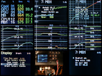
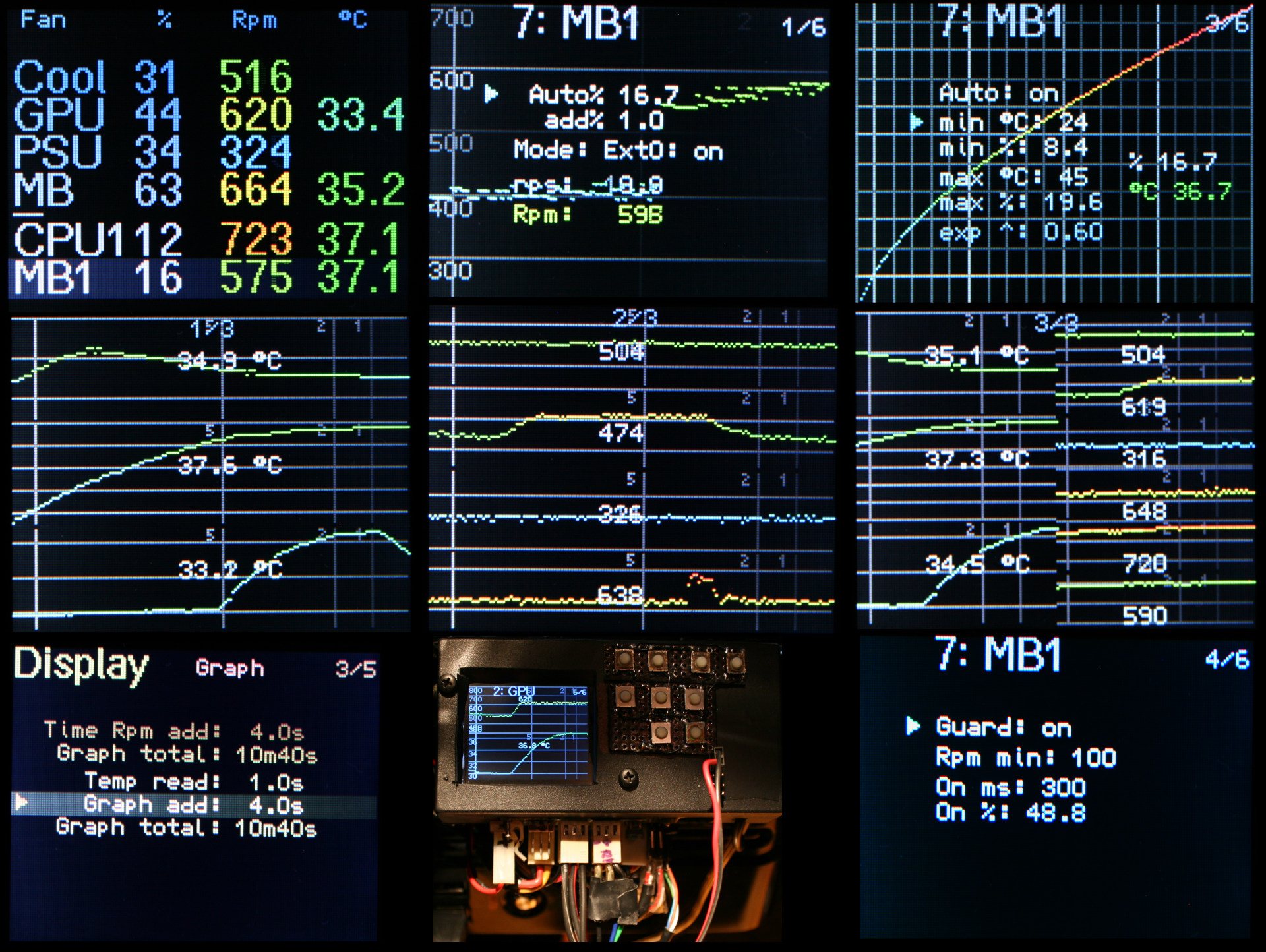
📊Features
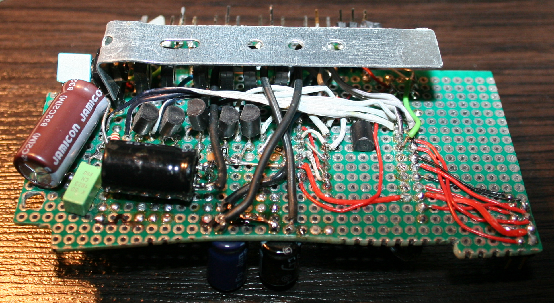
A shorter, bulleted list of all features can be seen in sources readme with more detail on electronic parts and schematic image here.
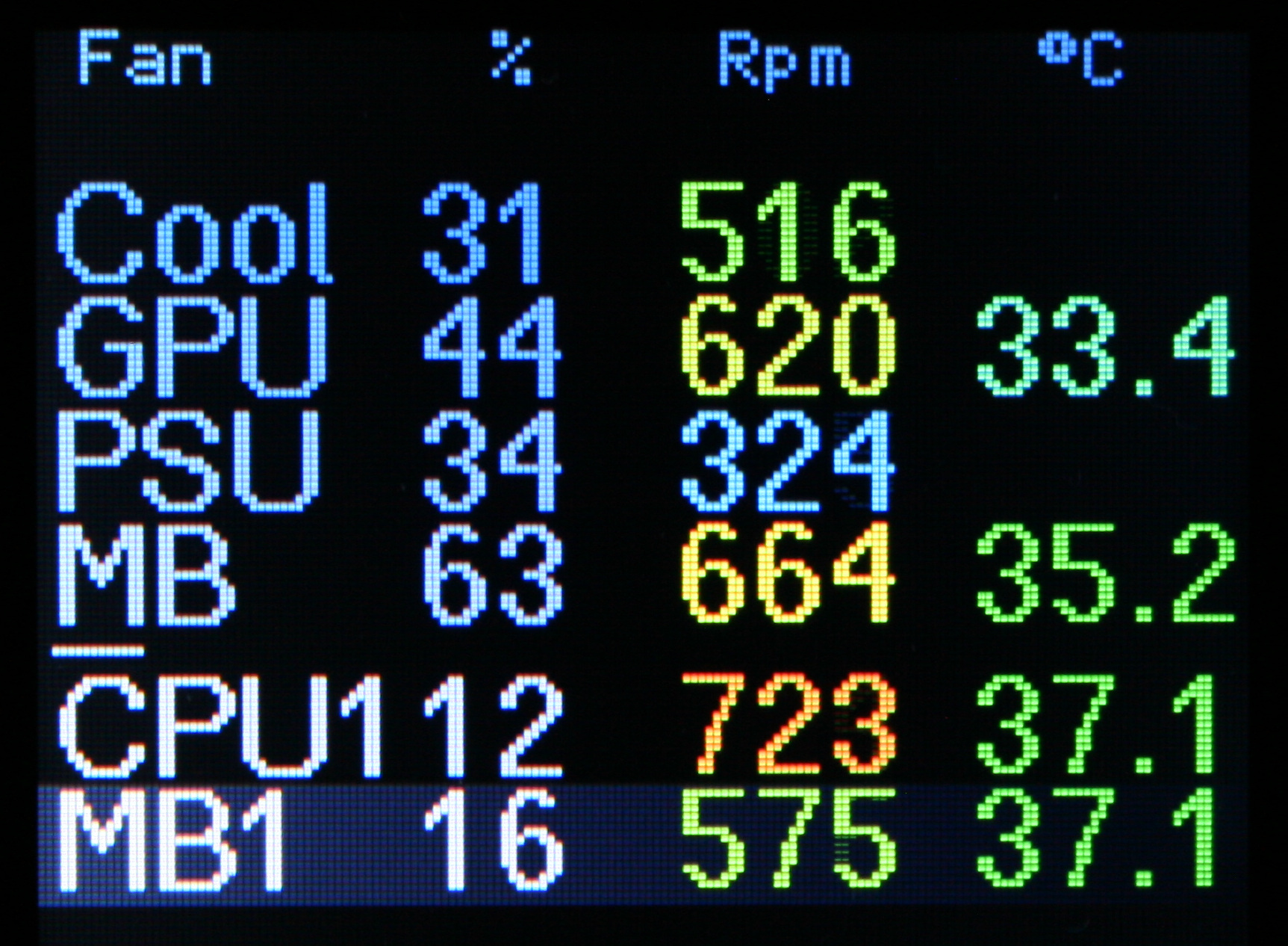
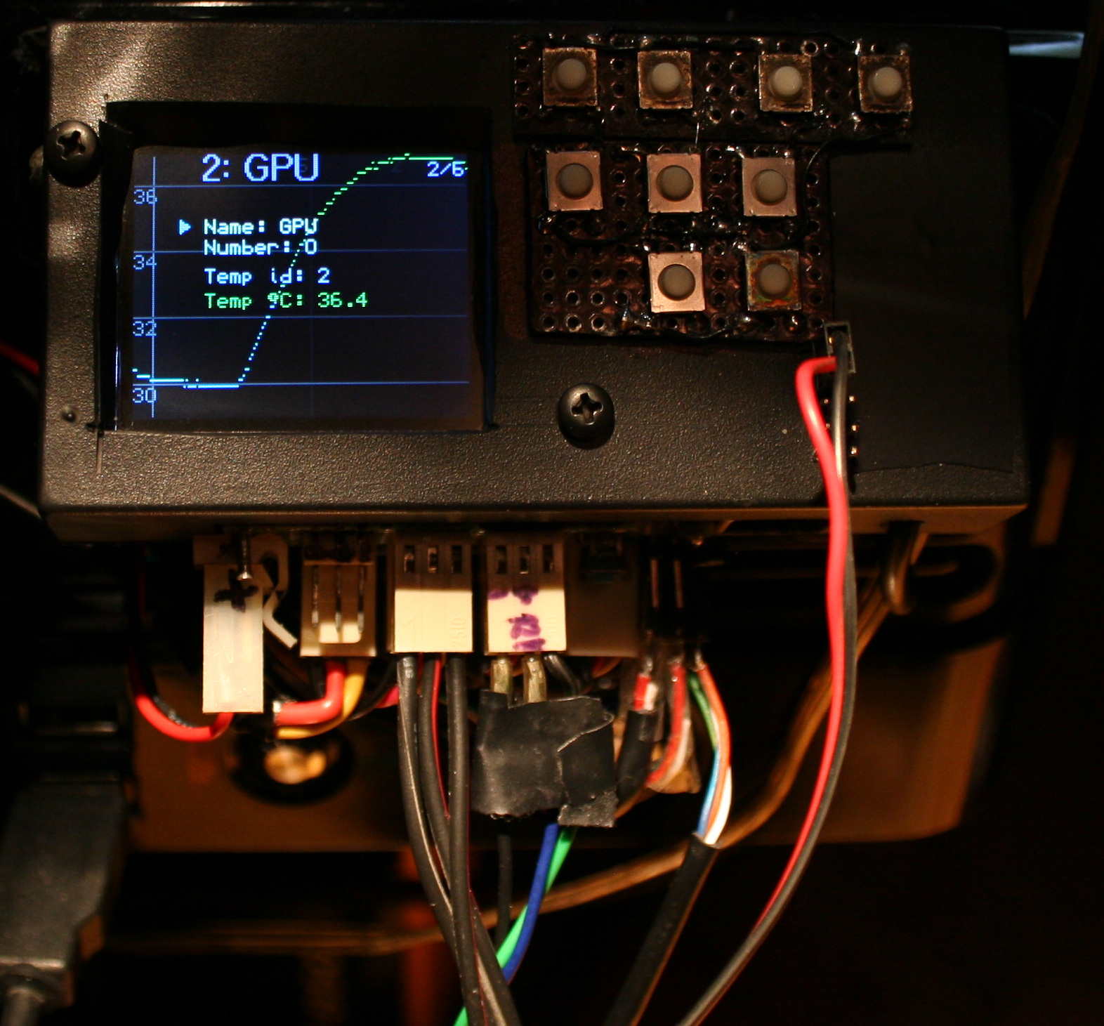
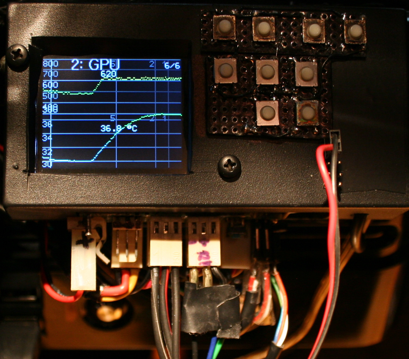
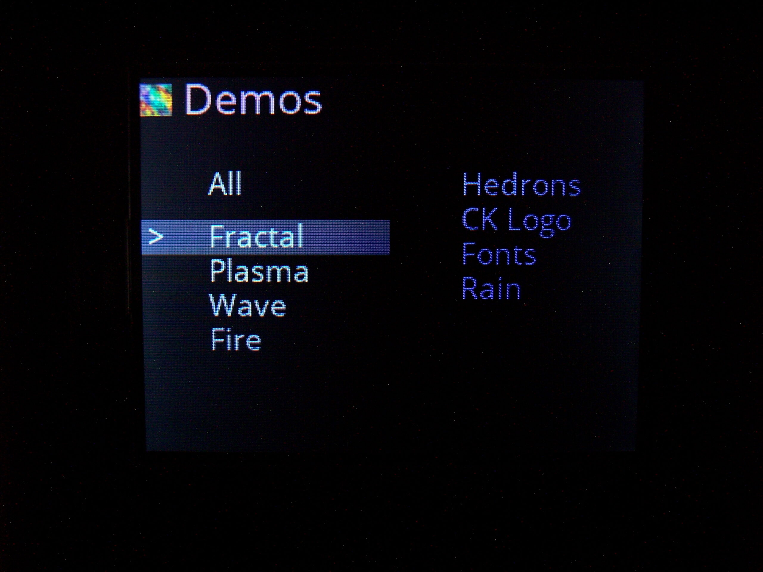
GUI
It has a 3×3 keyboard and a LCD color display (diagonal is 1.8″, 4.5 cm). I did years ago my keyboards this way, so it also came with 3 levels menu (GUI), many options and even full screen demos (why not). Of course it permanently saves all settings, in EEPROM.
📈Regulating
The main advantage of my digital fan controller is that it allows lower RPM than analog, which then makes PC slightly quieter. This is because a fan needs shortly higher power (voltage or PWM) to start, but can have it lower after it started rotating (I don’t mean the power started rotating 🙂).
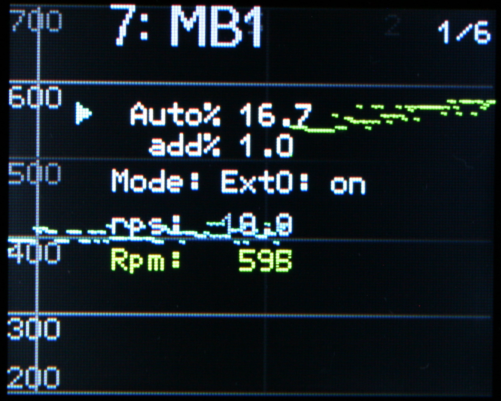
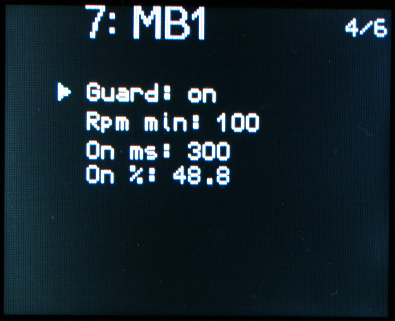
Next, it monitors RPM (revolutions per minute). So a natural safety feature here is: stop prevention (or in general RPM guard). It can increase power shortly to start again, even if user picked too little power to spin, or something stopped the fan.
Additionally PWM outputs can be used, for fans that allow it. Actually all of my old PC fans didn’t work with PWM, so I had to also make analog outputs (channels) for them at some point. I don’t know if it could be more universal, these channels require some other parts. So it can control analog fans (changing constant voltage) and PWM fans (changing modulated pulse width at medium frequency).
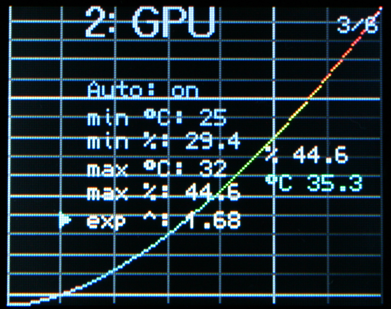
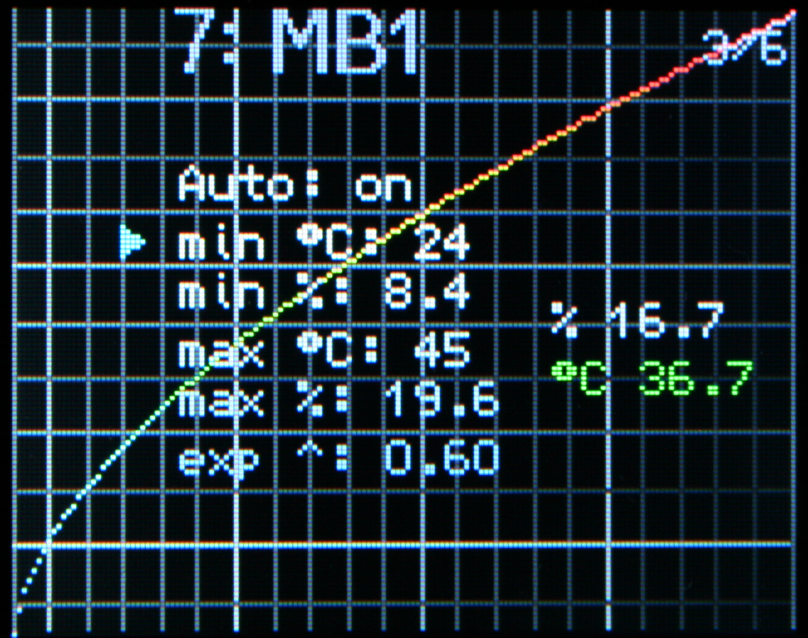
Optionally, temperature is measured. It can be used as feedback to automatically set fan power. This is naturally useful if sensor is on (or near) the heating part which fan is cooling. Sure, this can be possible to do with some software, that came with PC motherboard, GPU or a separate program. But it may not work on Linux or have all of my custom features. During summer I had my fans set higher, also even did set them lower when I wasn’t using much CPU (e.g. playing games or building C++). So hopefully this feature will make controller do it now, not me.
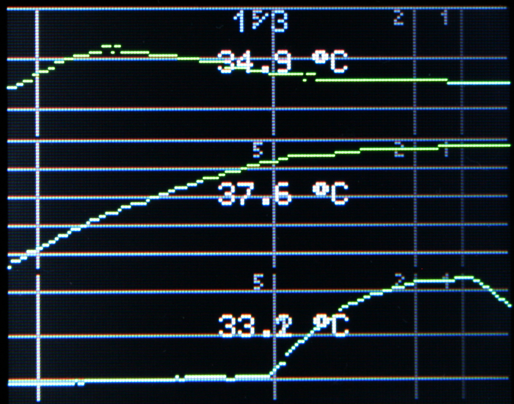
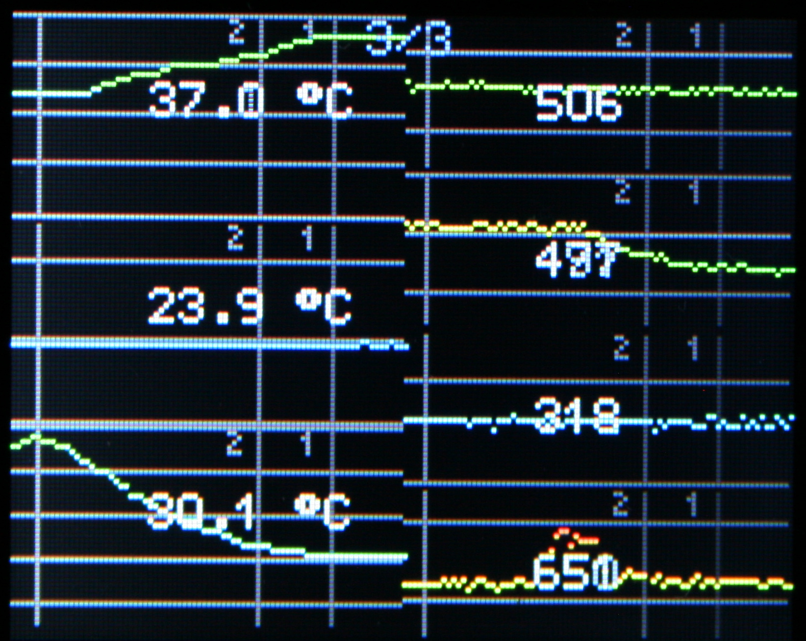
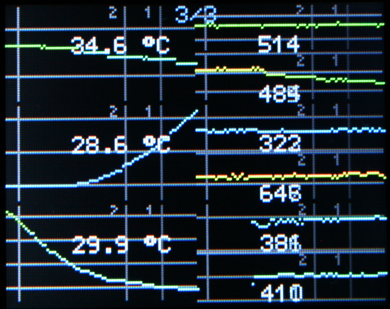
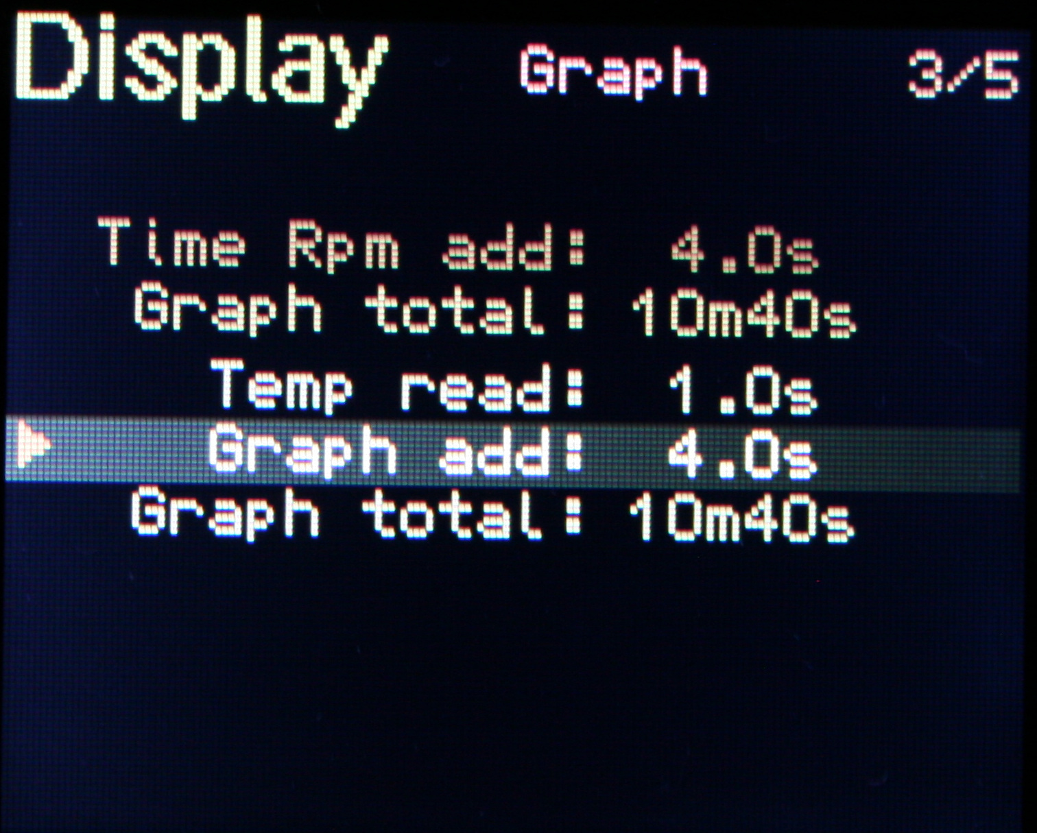
Since the display is 160×128 pixels, it can show graphs of RPM or Temperature over time. Even few smaller at once, but with less detail.
⌛Conclusions
Well it was a cool project, not just with digital chips, I had to use transistors with other parts too. I’m glad that one of the boards I have unused got to do something everyday. I hope it will last long. After all, my old regulators were really basic and much easier to repair (which wasn’t needed). Surely this thing is heavy, probably has too many parts too, but it doesn’t matter. It’s not like my PC weight matters at all.
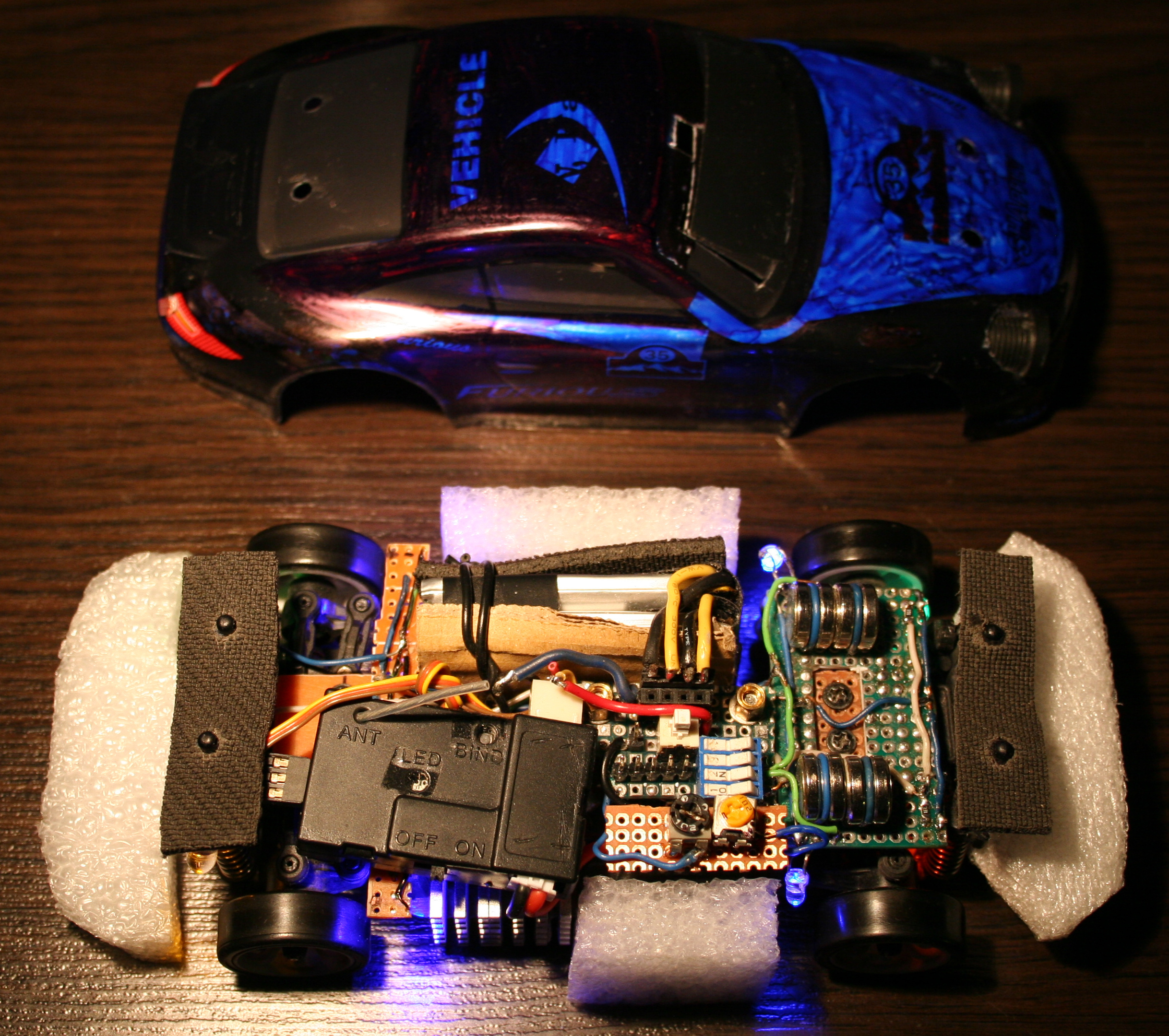
At end of 2021 I bought a WLtoys K969 RC drift car. I will describe here all the modifications I made to it. Also with few review remarks about it, less important comments and rants are italic.
▶️Video
Video here. Drifting in empty office on carpet and kitchen floor (best of montage). Camera was just from old phone: LG K10 2017 Car camera: Ion Snapcam LE, like mentioned below Software used to for video editing: Kdenlive on Debian GNU/Linux with KDE Picture gallery at end of page.
📜History
I guess I should write this chapter here, since being almost 40 requires (an attempt for) an explanation🙂. Well, as a child I only had a few (probably Russian) cars from 80s, Two did have a cable from controller, and the one that was radio controlled had only 1 button to go backward, which also made it turn. Yeah I also can’t even. As a teenager, at some point I got an RC car. It had rear wheel drive and used 27MHz. I think I drove it only 2 times. It was fast and meant to drive outside. It had rubber tires so it stuck to asphalt and would rather flip over instead of sliding. It seemed kind of hopeless (compared to today RC toys) and felt like something is missing.
✍️Motivation
In the mean time I got interested in WRC and 4WD on gravel, played a couple of such games too. And finally made my own Stunt Rally. There was a time when I was a lot interested in tires and car simulation.
Recently, once a while I was watching various videos about RC toys. Technology moved forwards a lot in them too. This way, I found out about RC drift cars of 1:28 scale, and after days of watching videos and researching what would be cheap, but still good for drifting at home (or office) I found this WLtoys K969 and saw how it drifts at home. I think I watched later other 1:28 cars (like Mini-Z, Mini-Q etc.), and realized that even thought they are much more expensive they aren’t much better. At least for me as a first car, I don’t intend to drive RC professionally or on tracks. There are also cars and people who prefer RWD only drifting (front wheels move freely), but I was never a fan of that.
So I think this RC is a nice, real life example, even if in smaller scale. It surely reacts and changes direction much faster than real cars. But is certainly less complicated, has no: LSDiffs, torque curve, gearbox, central differential, etc. In this RC all wheels rotate the same, electric motors don’t even need gearbox, suspension has only stiff springs, and there is no flexibility in tires, since those are from hard plastic here.
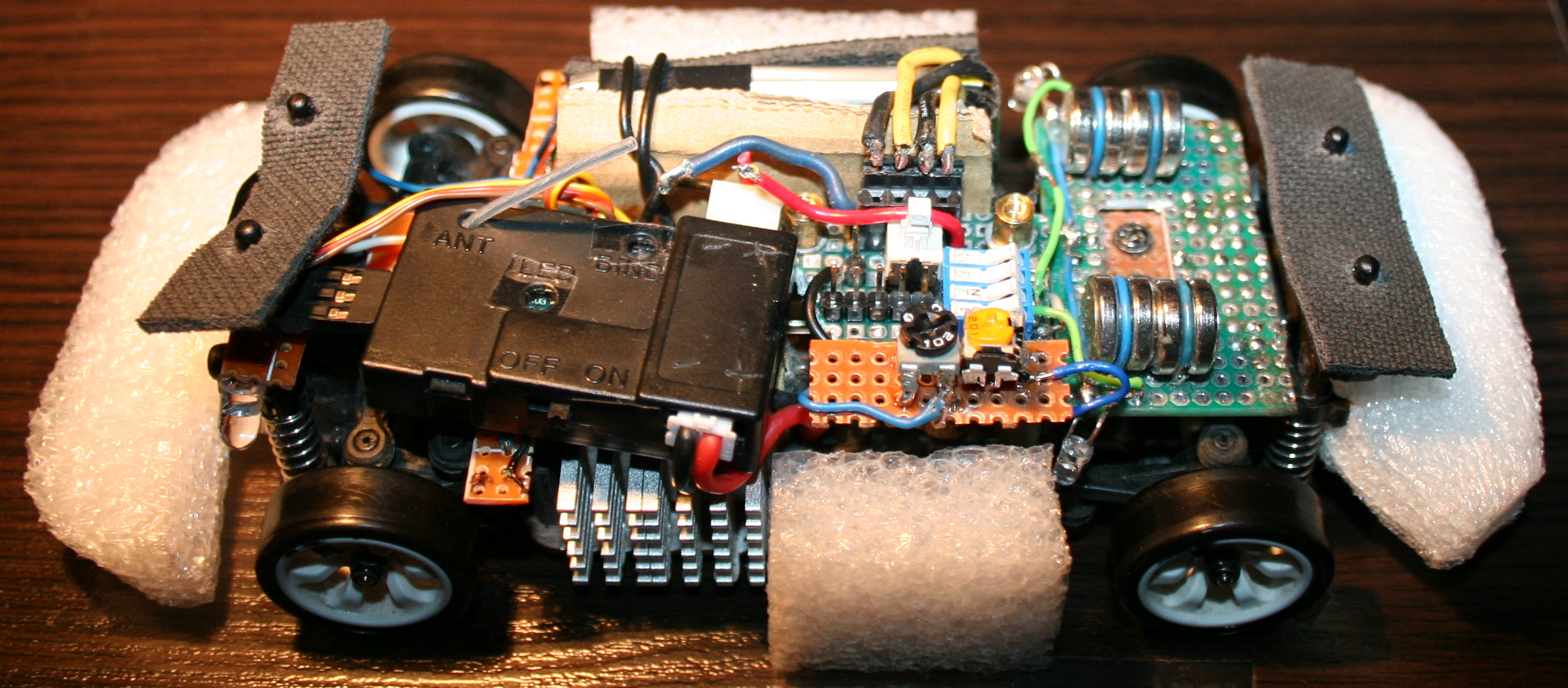
🛠️Modifications
So the things that I changed and added first to last are as follows:
Moved the pin from servo‘s steering arm higher for more steering angle range. There is a video here where it was easy.. But, a huge but here, as it turned out (for me) the upper hole for this screw is wider and I couldn’t just simply use the same screw from lower hole. Thus I had to go creative to achieve this. Since I soldered a lot, I came out with a solution of putting few wires together for right diameter, then soldering one end to a tiny PCB part (with 1 hole), and just bending 2 wires out of the other end. It still holds well. Visible on my last picture. I guess this isn’t that important but is very good to have. Without this, steering angle is lower, making wider turns, but you still can make tight turns by drifting with quickly spinning wheels to oversteer (lose grip on car rear).
Made throttle range adjustable. How to video here. BTW I recommend that channel, it has many good videos including for this RC car. This is actually the most important one. Without this it will be difficult to not spin out wheels all the time. For small rooms, throttle range needs to be even lower. Of course they made the car to be cheapest, and even didn’t add the most important adjustment to it, I didn’t need those side buttons, so why not having this instead. Meh, always have to make things usable myself.
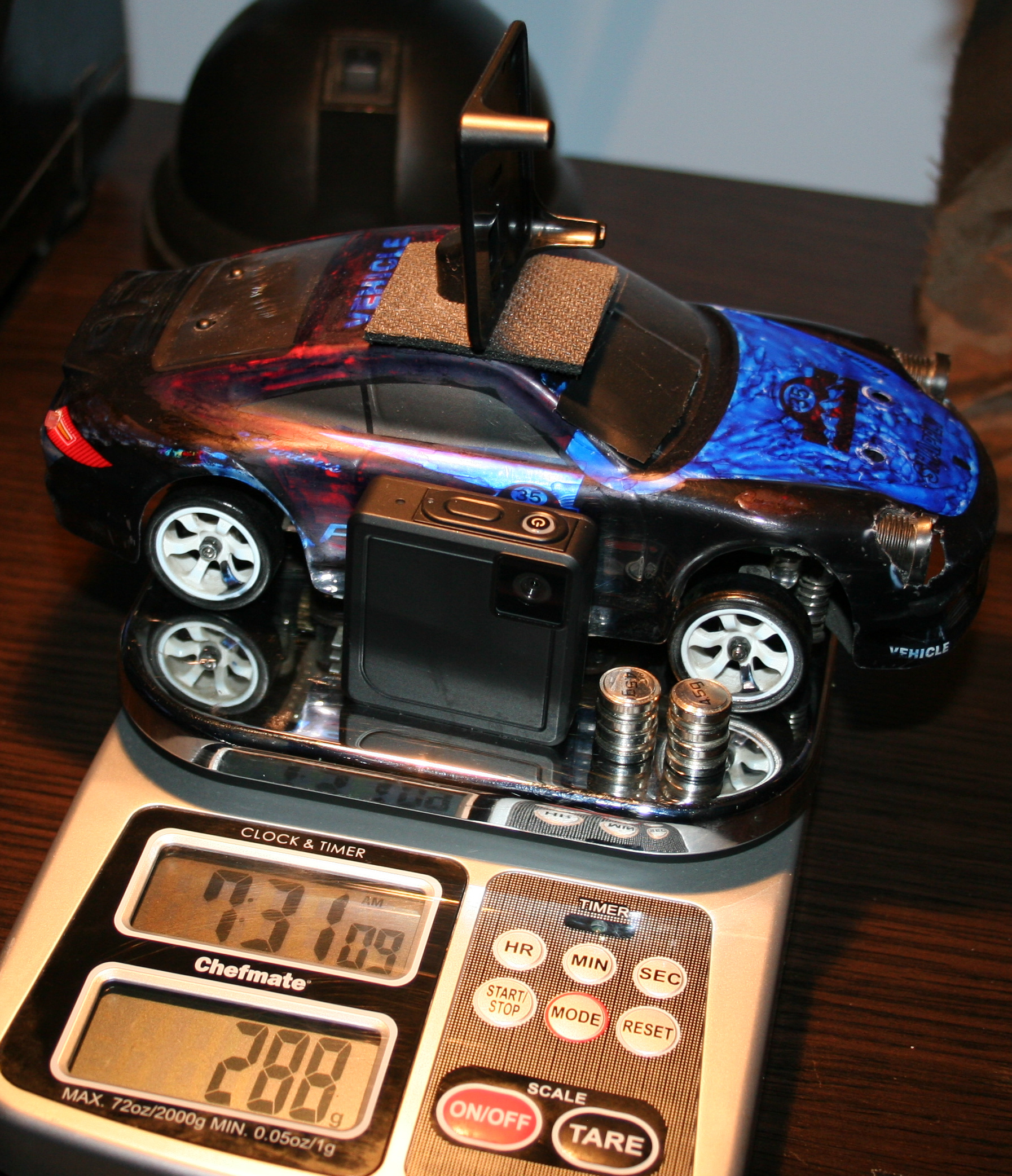
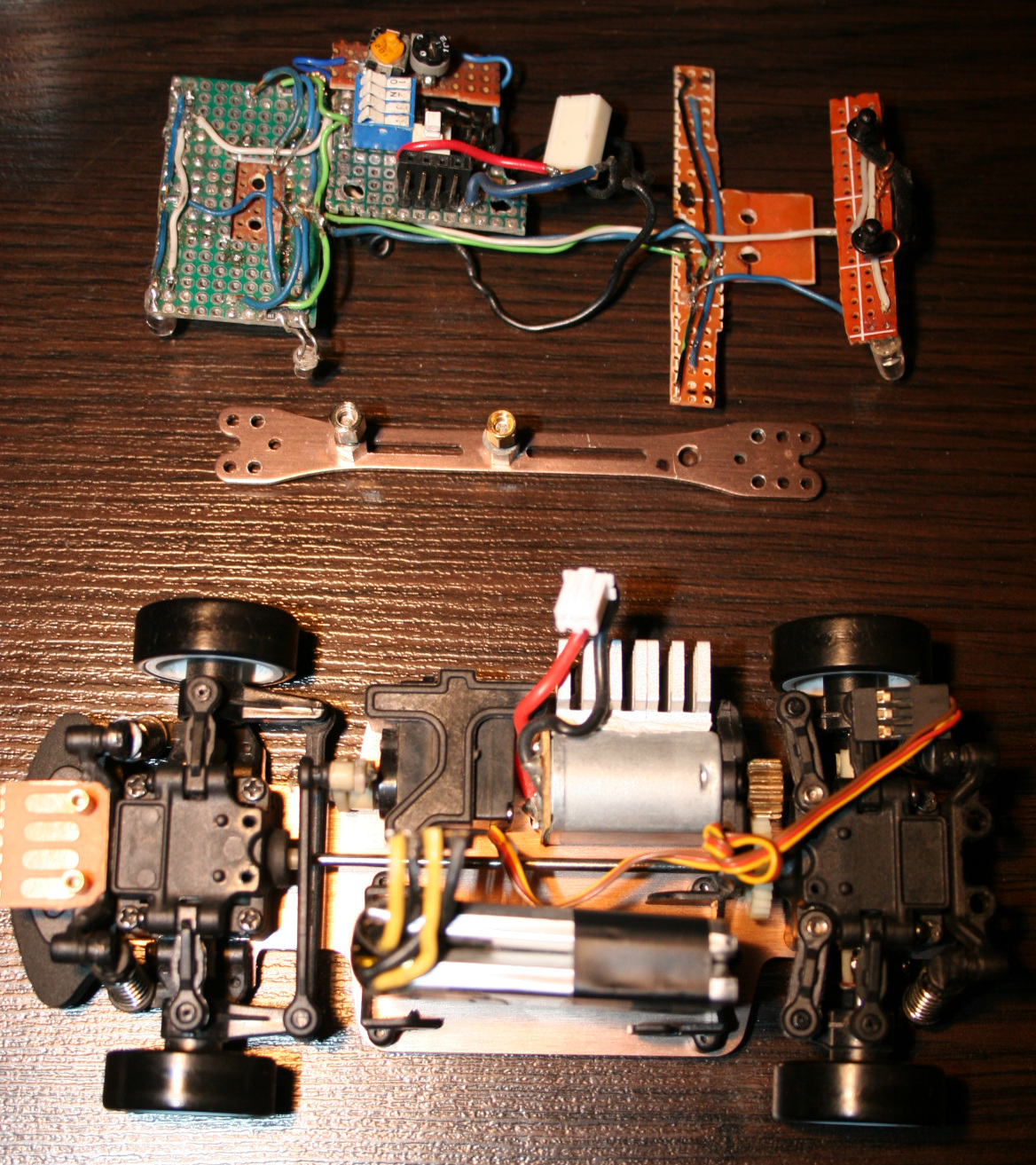
Added more weight on front. I cut out a universal PCB (my favourite kind) and made a place to solder down wires holding extra weights, they fit well. I used 4 in total, 2 on each side. One weights 4.5g, so this is 18g added on front wheels. This made center of gravity to shift (like 6mm or so) towards front and made the car oversteer even more, it drives better. There were some videos on doing that, just gluing 10g weight. Isn’t crucial though, still can drift without this. My front PCB is also used for lights and wires.
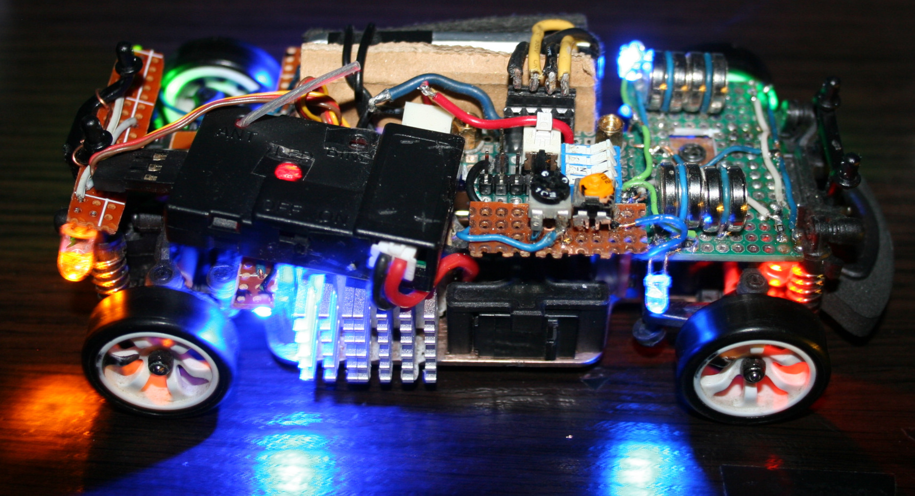
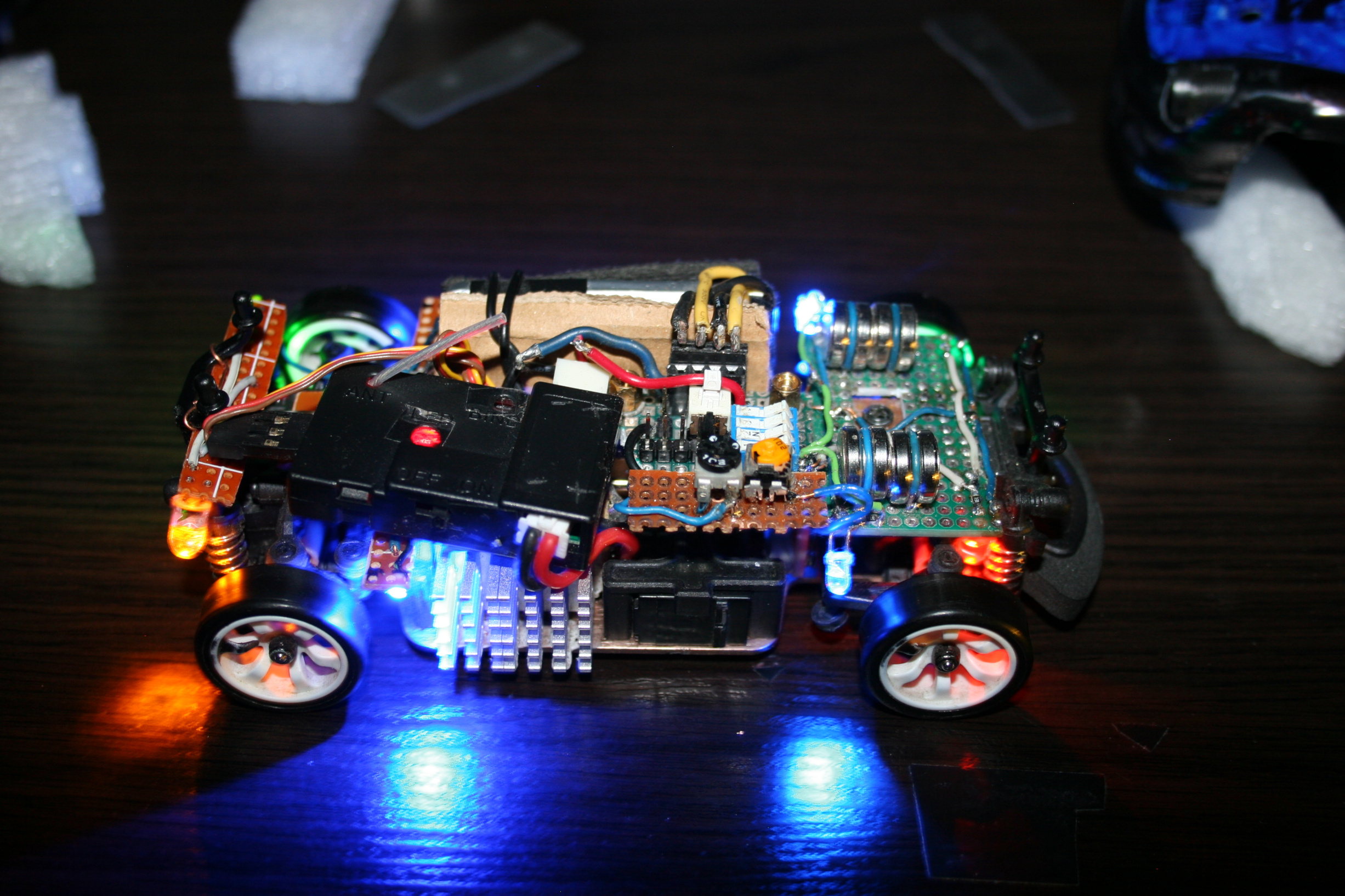
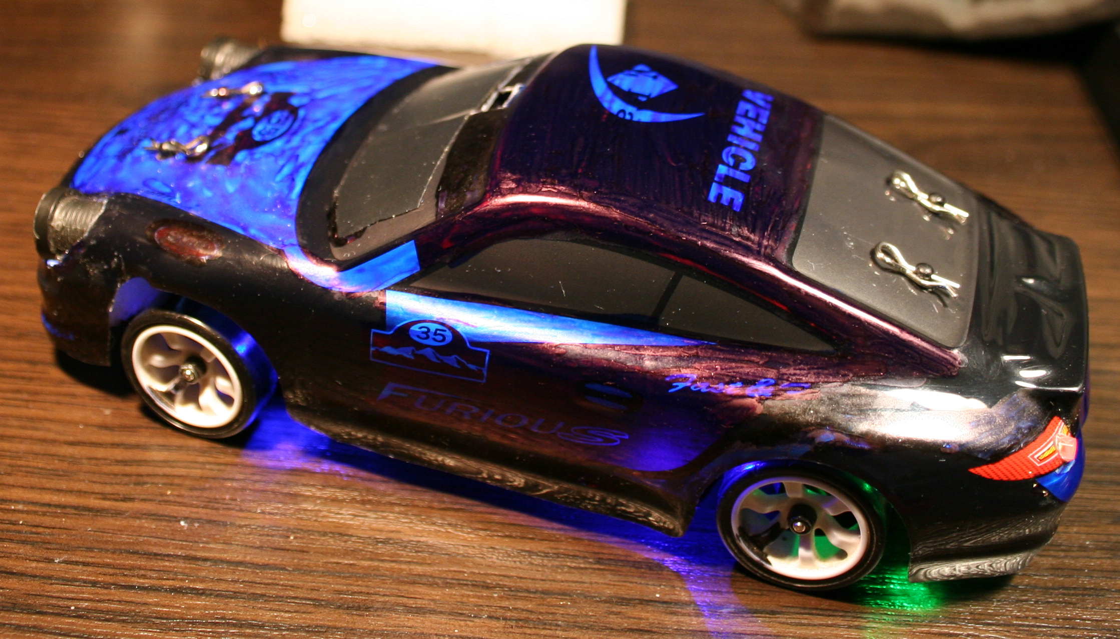
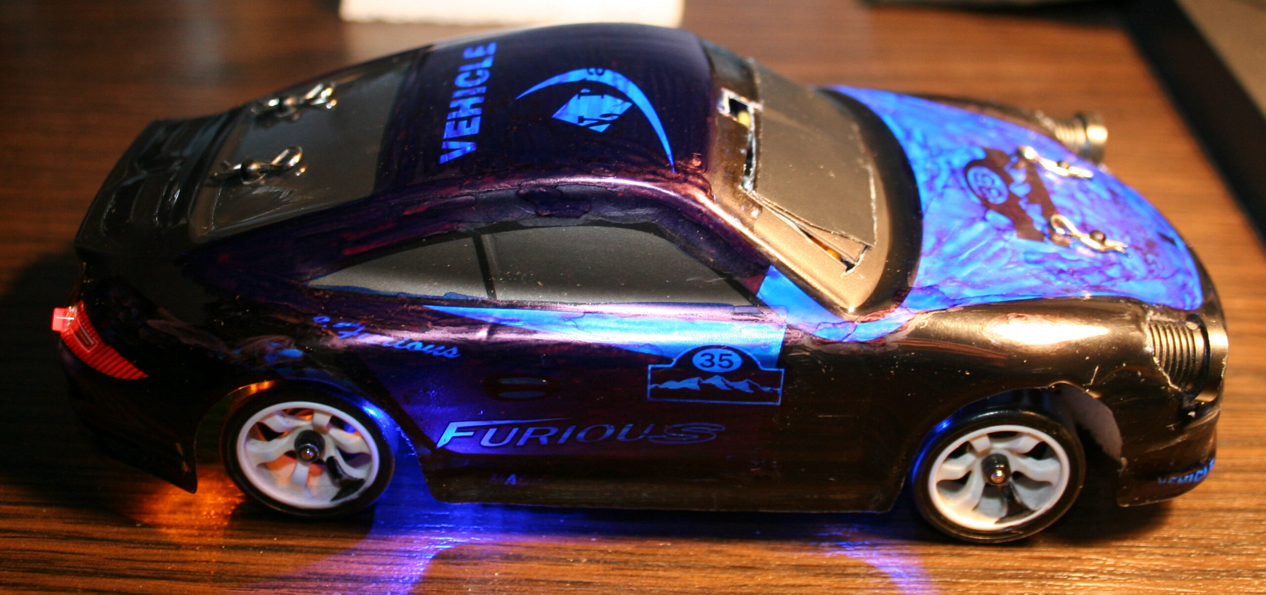
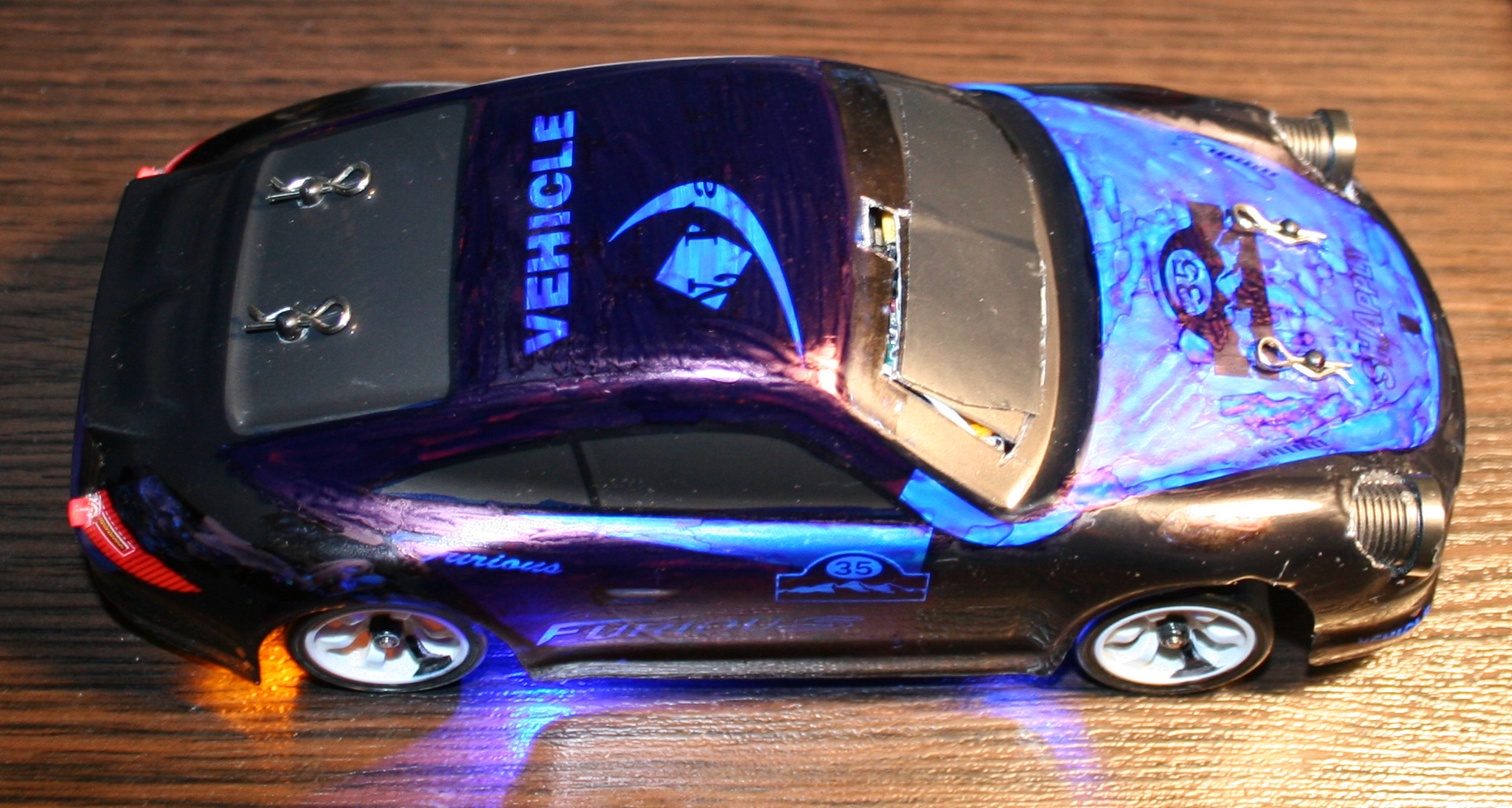
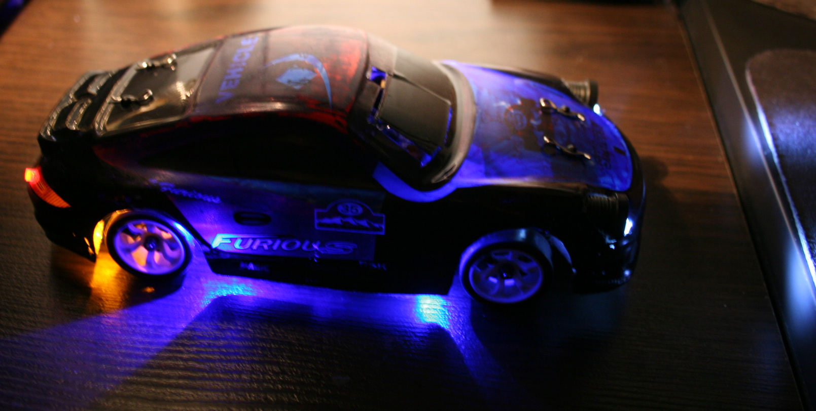
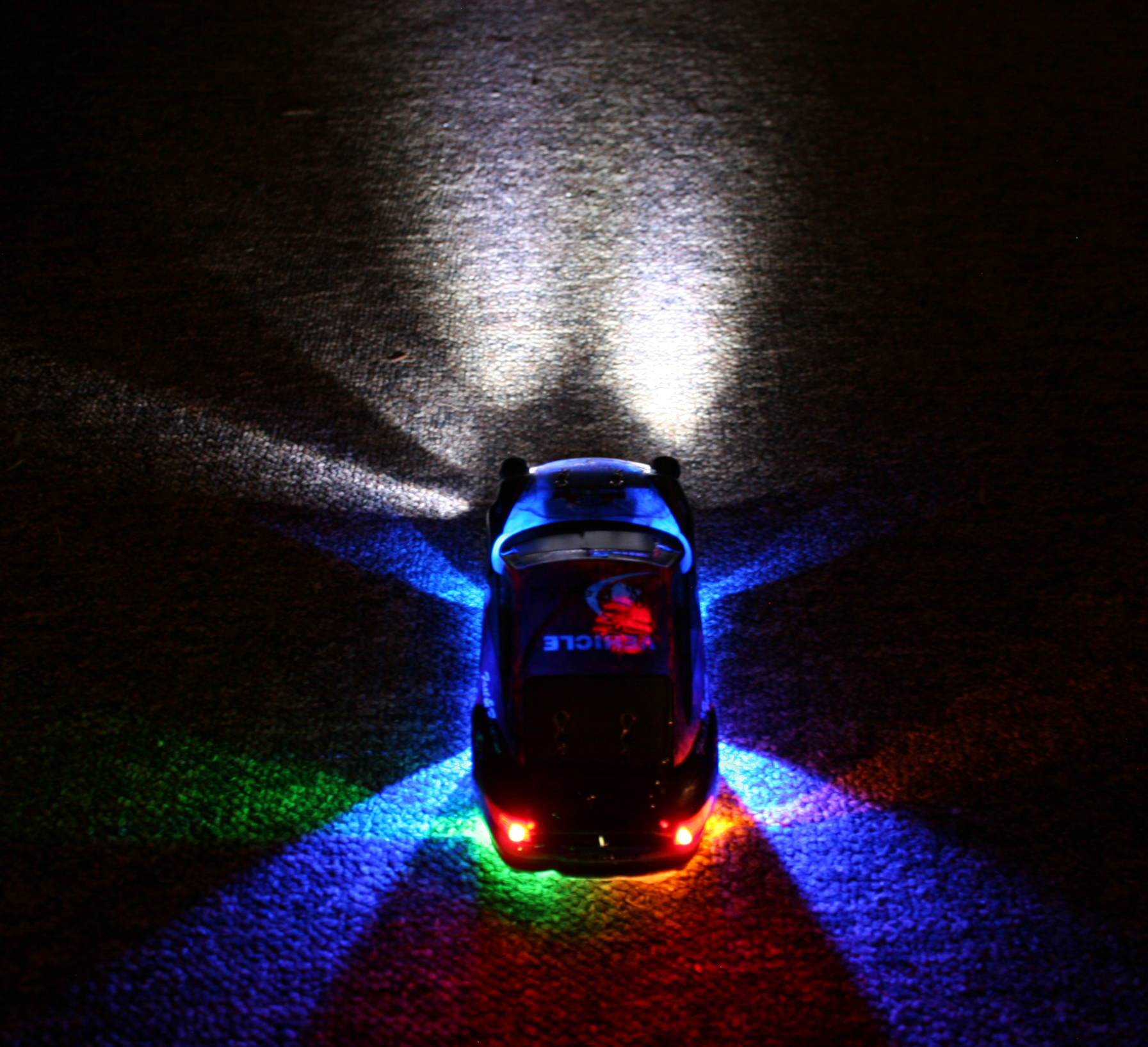
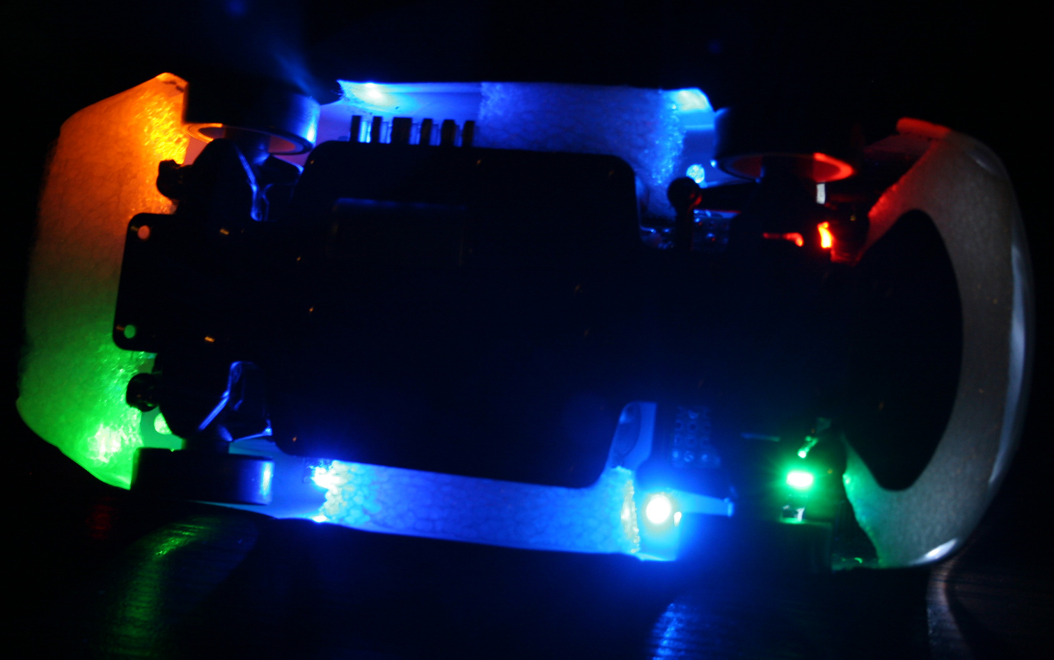
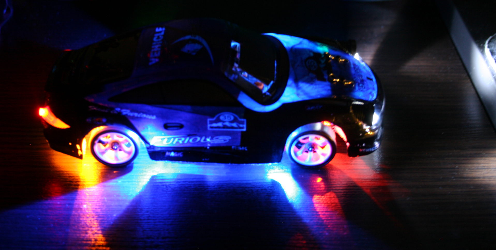
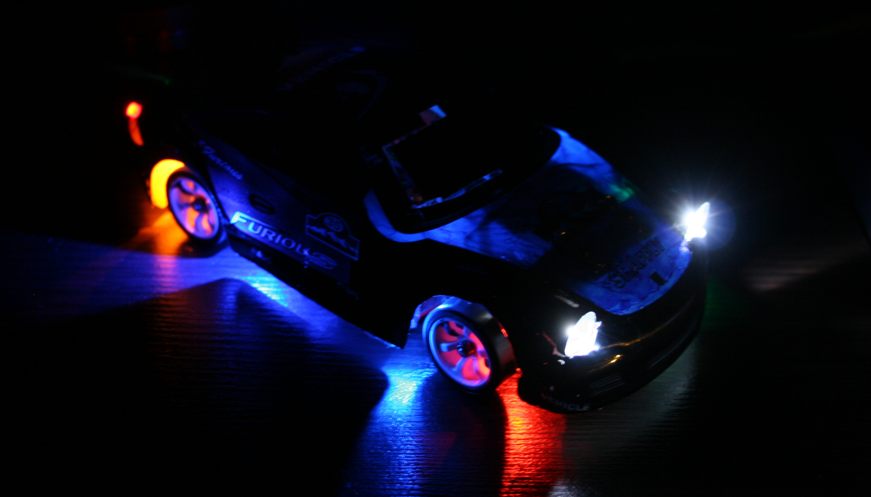
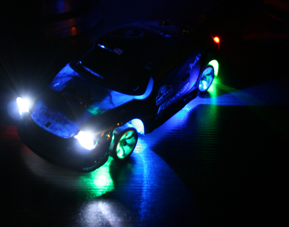
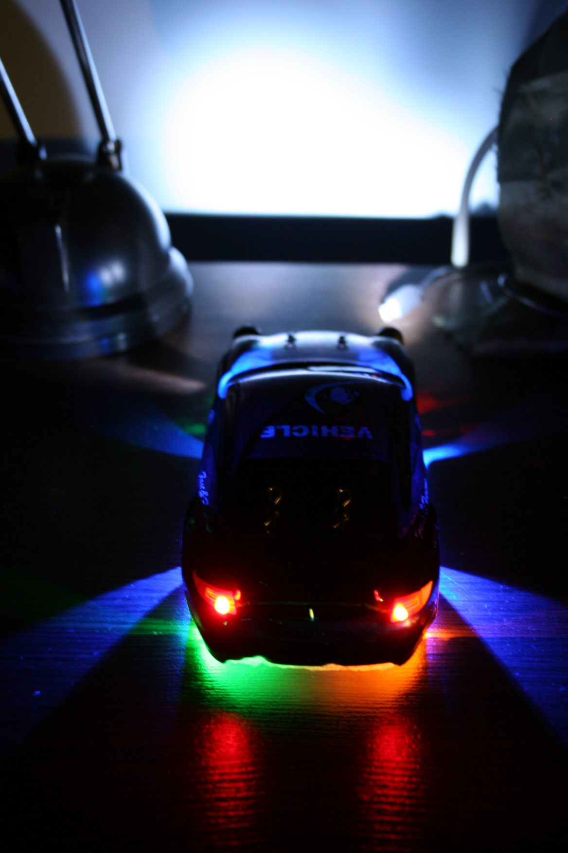
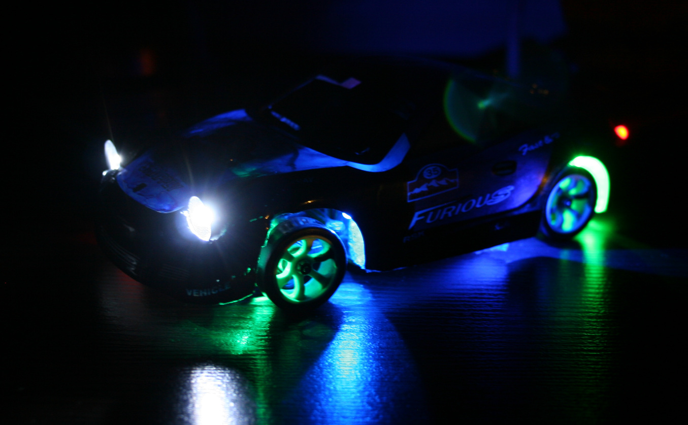
Added front and rear car lights. They are good for better orientation of how the car is rotating and what’s its direction. I mean it is actually easier (for me) to tell this by seeing those lights on floor, especially if car is far. The only way of doing this is making holes in chassis and hot gluing LEDs to it. I’ve spent too much time with lights, first making them in car. This way anytime I hit something harder they would change angle, go loose or break off. I also made a second mistake and made holes bigger to have LEDs with cases. It turned out the cases were too big and so long that made wheels hit them, if chassis is low. I will cut them to minimum and glue again. Good thing about that hot glue is that I can actually melt it with soldering iron again when I change my mind.
Made the RF sender battery use a 18650 LiPo. I don’t get why they didn’t already (was probably cheaper). When full, 4 AAs give 6V, LiPo is 4.2V, but RF sender still works. I thought it would be more difficult, but it was really easy. Just throw out 4AAs compartment and place the 18650 or any other LiPo here. Doesn’t seem to use much power, I didn’t charge it for a month or more. I only don’t know if it maybe decreases range? But with all being digital it may not be affected.
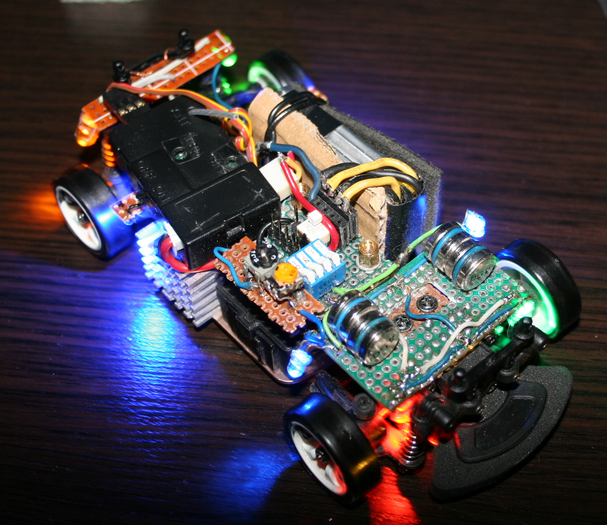
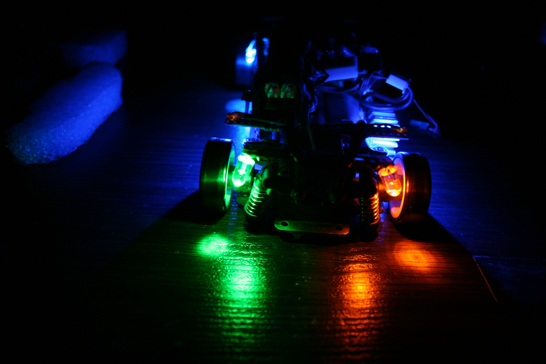
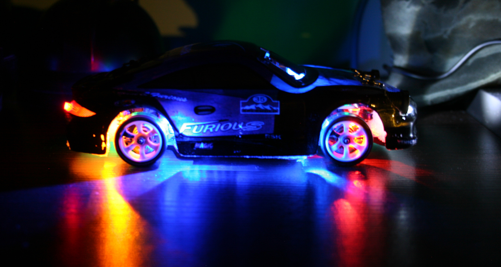
Added bottom lights. I had some old LEDs lying around, now 2 are on rear before wheels and 2 on front before wheels. Their location with chassis holes makes this cool blue X on floor now. I had only two 3mm LEDs so I also used 2 SMD LEDs, which I soldered out from those LiPo chargers (who needs them, red when charging is enough, and were so bright that I couldn’t even?). Then I added two 5mm LEDs (too big, SMD are better) green on left side, yellow-orange on right, located right after and above wheels. This turned out to be useful to know even better how the car is rotated from distance. So later I added same (close) colors to front, behind wheels. I soldered all on small cuts of universal PCBs.
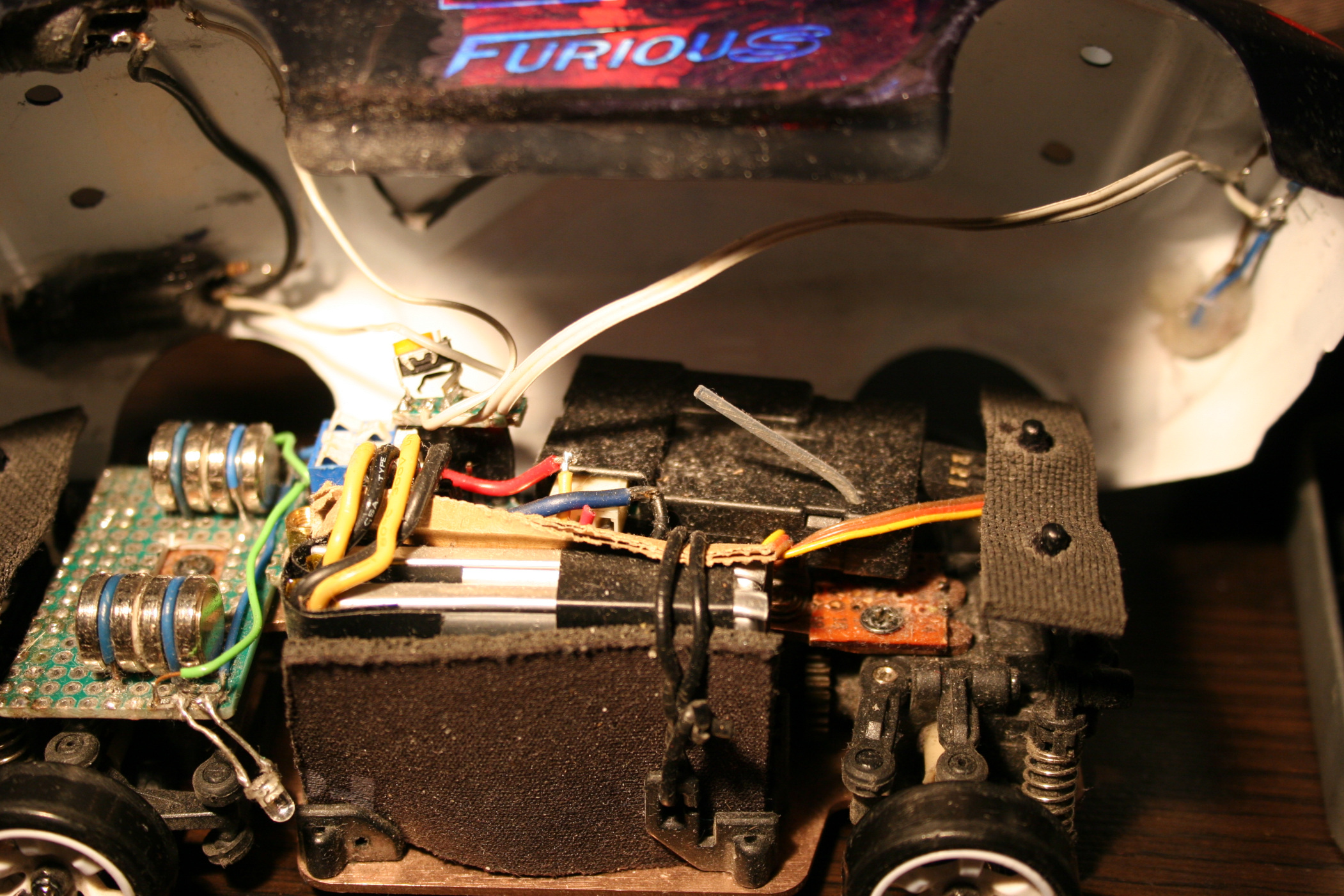
Changed to a bigger car battery. The included 400mAh battery allowing 30 min runtime is laughable. Yeah I can’t imagine drones with 15 or less minutes at all. It was cheap and light, which is why they made it, right. After all, the freaking top speed has to be highest, like it was important at all. It drifts at much lower speed already. My new battery is 1200mAh and allows 1h 30 min drive time (so 3x more). It was made from two LiPo 603450 batteries, each size: 50x34x6mm. Glued with tape, fits nicely in same place, is just much higher and it weighs 45g. Secured it with some cardboard and mouse pad fragments on sides and wire (with thick insulation). I just had to remove their protection, because with it, it would stop for few seconds when pressing throttle too rapidly (very annoying).
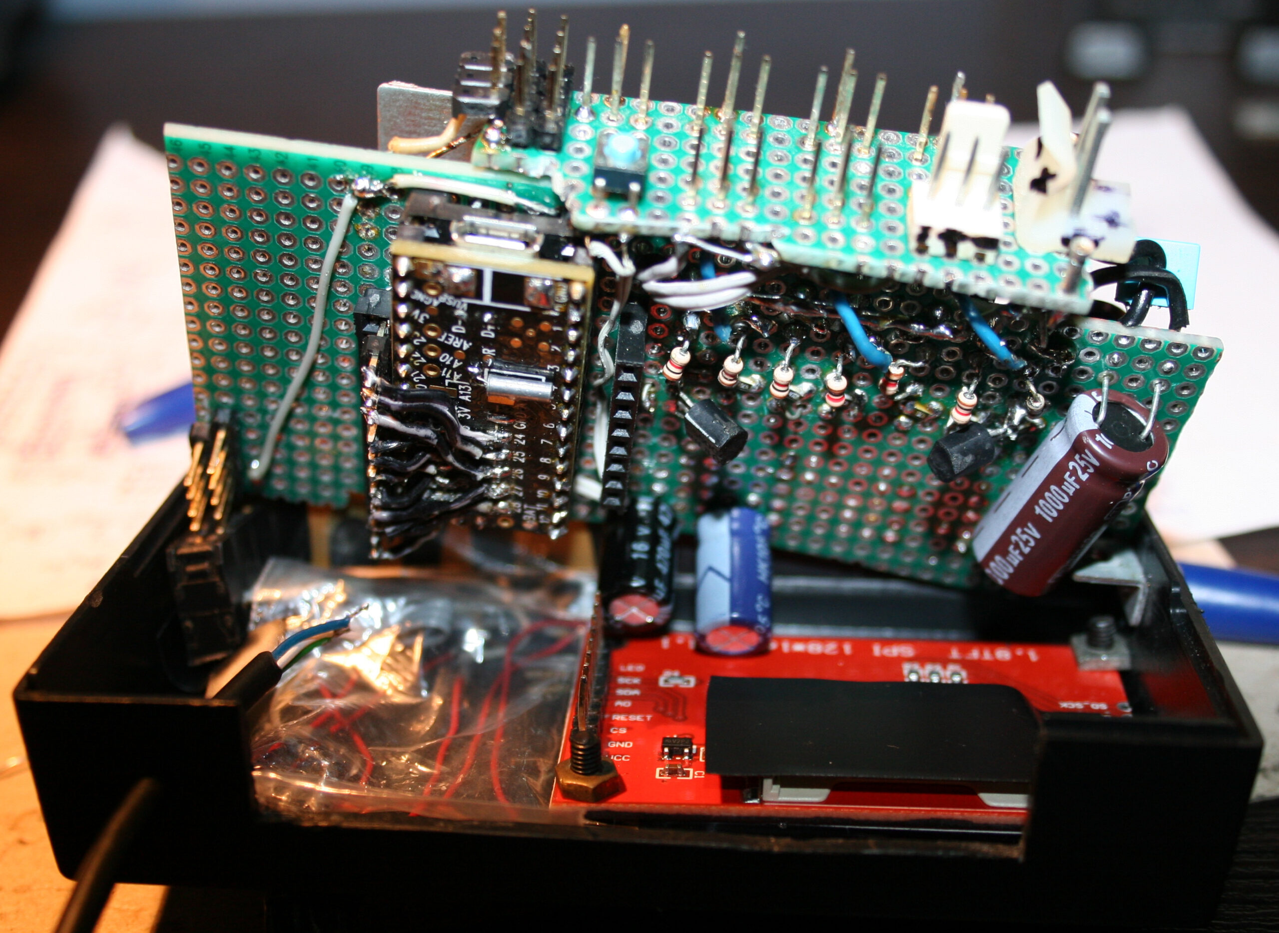
With new battery I’ve also done new electrics in car. namely:
4 pin socket for battery, normally plugged in.
ON-OFF switch. I used a 6 pin Tactile Power Micro Switch (self lock on) 7*7mm to switch + from both LiPo batteries.
4 pin socket for charger, plugged in when charging.
4 micro switches for lights (on-off, one small package). I added 47Ω resistors at end of each. I call this a fuse box, their purpose is prevent battery short circuit if by accident some wires connect.
5 pin socket (3 used now) to connect chassis lights.
2 trimmer potentiometers 1kΩ, for dimming car lights and bottom lights.
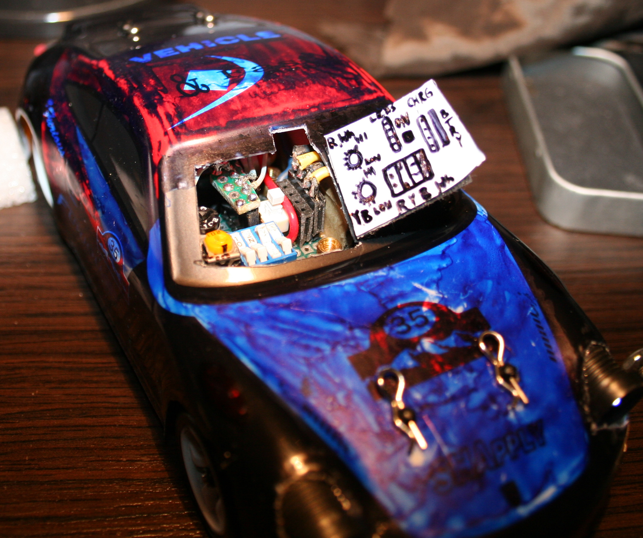
All this required access, so I made a “door” in half of car’s front windshield.
In total, the boards with bottom LEDs and all electrics weight 27g. Seems too much, but whatever?♂️. Each LED has a 330Ω resistor before. LED calc can be used if needed.
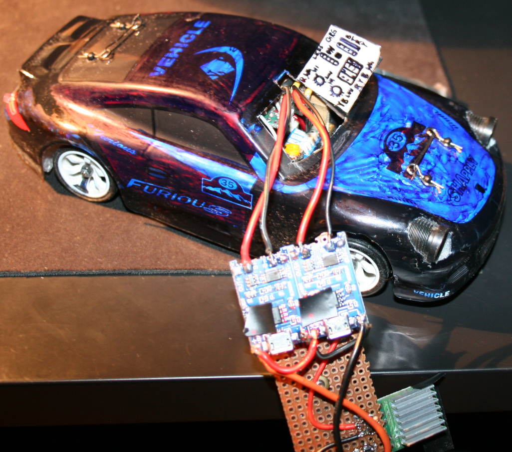
Charger Made using 2 popular modules: TP4056 / TC4056A Lithium Battery Charger and Protection Module. Just added 4 goldpin connector for car socket and that standard 4 pin PC connector for 5V. It does charge the battery in about 1h 30min. I’m not sure if it’s too fast or okay. The 4056 chips are heating a bit too much (at start), so I’m using a small copper radiator on them. Besides of removing blue LEDs from chargers (mentioned earlier) I also reduced the red LEDs brightness, resistors are now 20kΩ (way more). I hate this approach of adding LEDs, even for “turned on” indication and making all LEDs as bright as it can be. I guess if they could they’d made them visible from space or neighboring countries, that would be the best commercial.
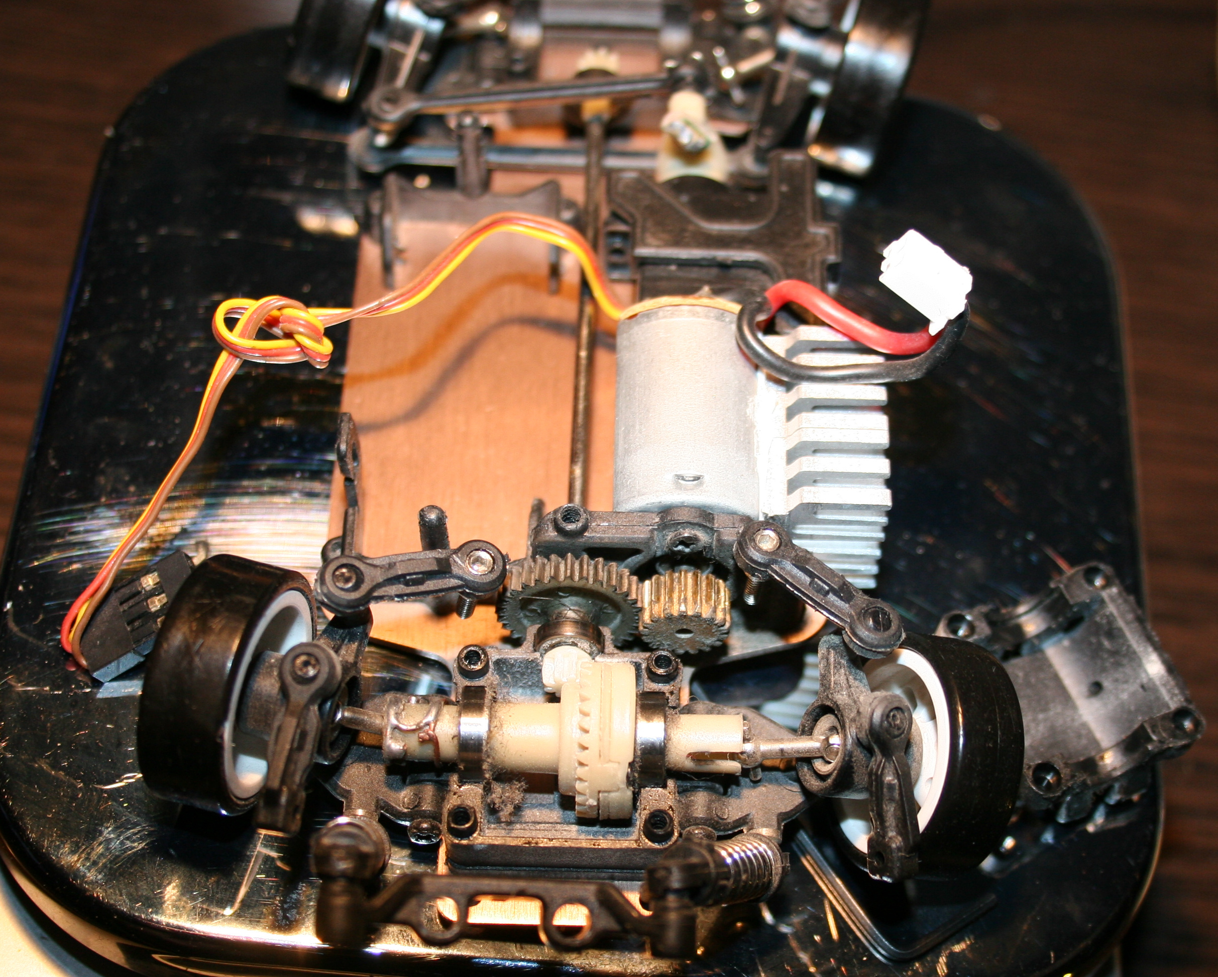
Radiator for main motor. Having more time to drive showed that it heats a lot, especially in smaller rooms. So I used thermal glue and glued some small aluminum radiators (1 cut to match motor length) bottom to motor and side to car bottom, which is aluminum, so good for cooling too. I’m guessing an even better way could be using copper tape around motor and gluing that to car bottom? Not sure. Either way some cooling is needed and would be better to have it done already.
Added some rubbers (cuts from mouse pad) below chassis mounting points (I saw something similar in a video). And later some foam around the car, better late than never. This is to soften hard hits, those happen a lot at start when first learning to drive, especially without reduced throttle. Additionally, at home I do jumps sometimes, banked and U turns (up to like 80 degrees, on a bent sheet of metal I had in cellar) and flip overs can happen this way etc.
At some point while reversing I almost broke one differential end (those, like all parts are plastic). I only noticed when one wheel wasn’t driven. But I managed to put it together with a wire soldered around it, so it doesn’t fall apart completely and works, a bit uneven though. Parts are freaking expensive, probably few times more than their worth. I hate this approach. If someone bought all parts separately it would cost like 2 or 3 times more than the car itself. Plus the waiting for shipment takes time.
After some bigger hit, I broke the thing that holds chassis on front. It is filled with holes and plastic, so no wonder. I made something stronger (and heavier like all I did) from a metal part, M2 and M3 screws. Is more difficult to use but should last longer, if I don’t break the plastic part that it’s mounted to.
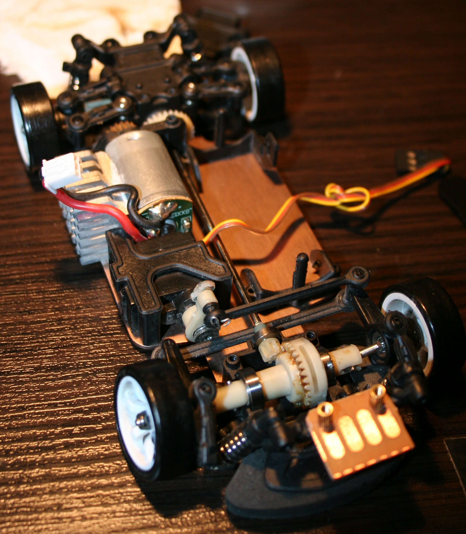
Added a mount for camera on roof. Camera is Ion Snapcam LE, it weights 28g, with its own battery. It even lasted longer than car drive. I didn’t yet make it lighter by using car’s battery. Not sure if I will. Unfortunately, videos are horribly shaking when driving, because of uneven wheels.
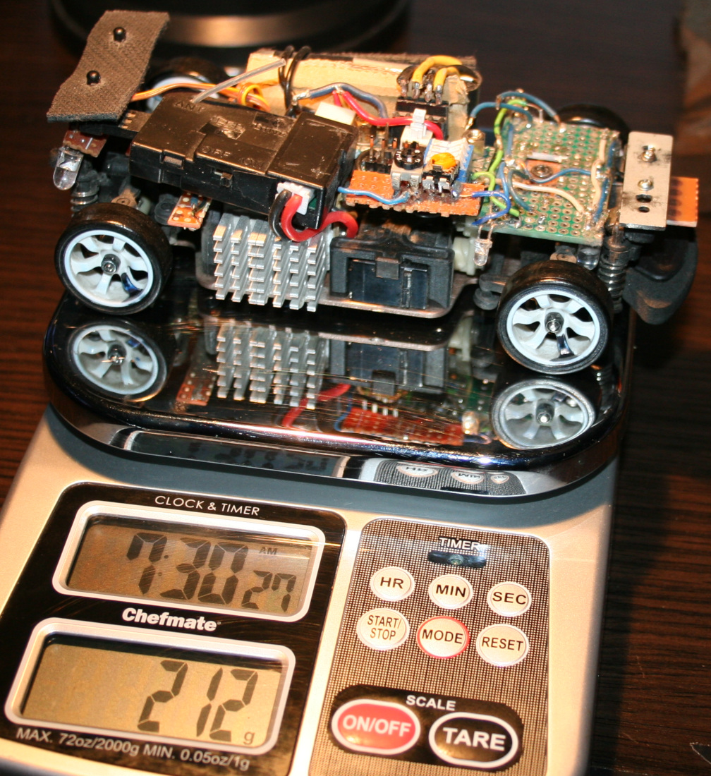
In total the car with camera weights now 288g. So it is a lot more (was 160g at start) and the front suspension won’t allow more. Without camera and extra weights it is about 240g. I think it still drives well despite the extra weight. But surely when lighter it was quicker and more responsive (less mass and inertia).
Now I’m waiting for new wheels, with aluminum rims. The default wheels on this cars are cheap, all-plastic and uneven. Even like 1mm difference in height when rotating. This makes the car shake a bit. Surprisingly it doesn’t affect driving somehow, and it wasn’t easy to spot. Only slow time videos showed it and those from car camera, which are rather unusable.
Maybe for future (not sure if I’ll try/do any of these): I was thinking of making the controller use IR distance detection for throttle (instead of potentiometer which I already once cleaned since dust made it go chaotic). Using a MCU (Teensy 3.2 which I have lying around doing nothing) with LCD, buttons and rotary encoder for a GUI that allows adjusting all ranges and offsets without potentiometers. I also had an idea about having a light MCU in car to use RF (e.g. NRF24L01 2.4GHz modules) to send some measurements to controller MCU, like: battery voltage (for remaining drive time), motor temperature, car acceleration, rotation and direction (from those popular new accelerometer chips), and making all car lights toggleable and dimmable (with PWM) from controller. Lastly very doubtful, but maybe if I used PC mouse optics and chip I could get real velocity and position on some surface.
⌛Conclusions / Review
I personally can’t imagine having fun with an outdoor, fast / touring car, with rubber tires. Neither with a smaller car that doesn’t have 4WD and drift. And those big RC cars that can slide on gravel (and jump up few meters) are quite big, very expensive (I seriously would buy a new PC instead) and require a big area or a track. And outdoor and indoor tracks aren’t close, are likely paid per hour and have other people. Plus parts for more expensive cars are of course more expensive.
To summarize, I would recommend the WLtoys K969 car, especially as first RC car for indoor use, with more fun because of drifting. But with a few remarks.
I don’t really recommend driving this car without modification 2 (throttle range adjust). I did it at start and it was chaotic. Some say modification 1 (more steering) is also crucial.
Another thing that many say, is that the 2 smallest gears wear out rather fast. Those that drive each differential, both from plastic again. Why on earth aren’t all gears from metal.
Well as I mentioned few times already, nearly all parts are from plastic, which can be a problem. Surely is for small gears. Later if you drive on uneven surfaces or jump, etc. then mountings for suspension will wear out or break (since closest to floor and from plastic). Still (and maybe that’s why) there are many metal upgrade parts and kits, but I don’t recommend any, at all. I have seen too many negative comments from people who say that those don’t even fit together, are bigger, leave less clearance etc. So they just look cool, and that’s it.
The rest of my modifications were optional and just an easy hobby, that lets me spend some fun time, but not with my PC as usual.
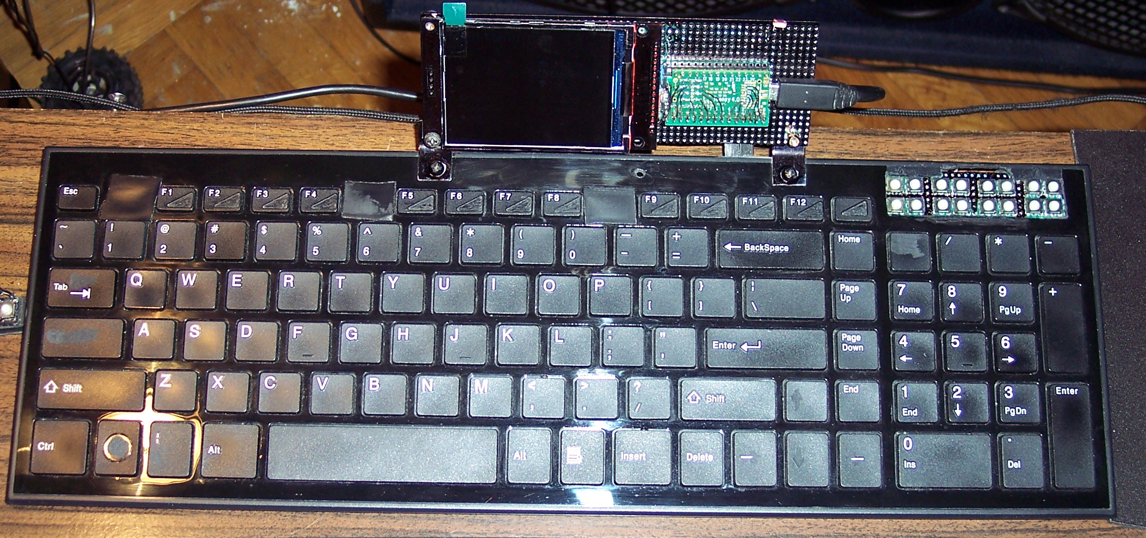
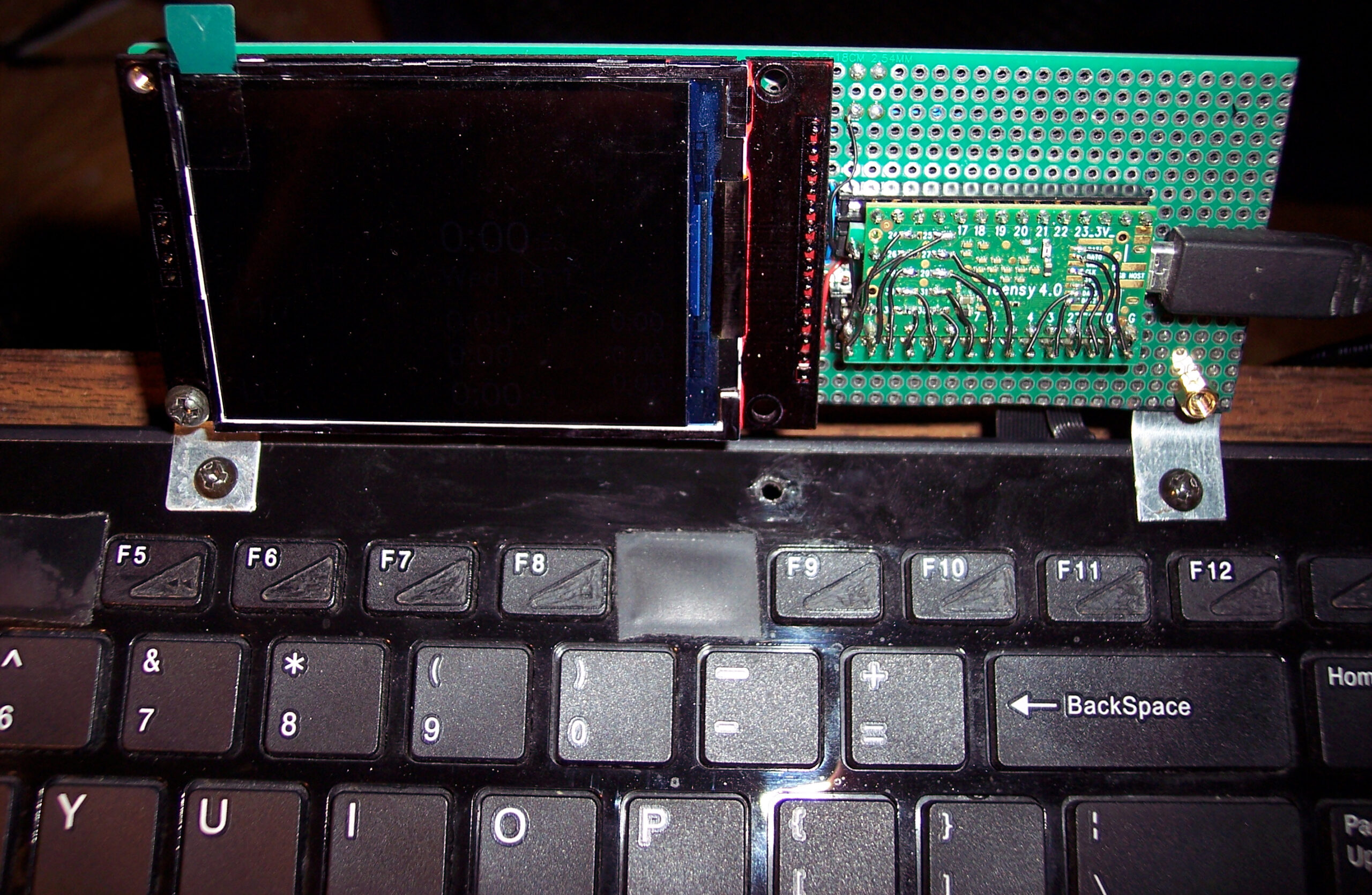
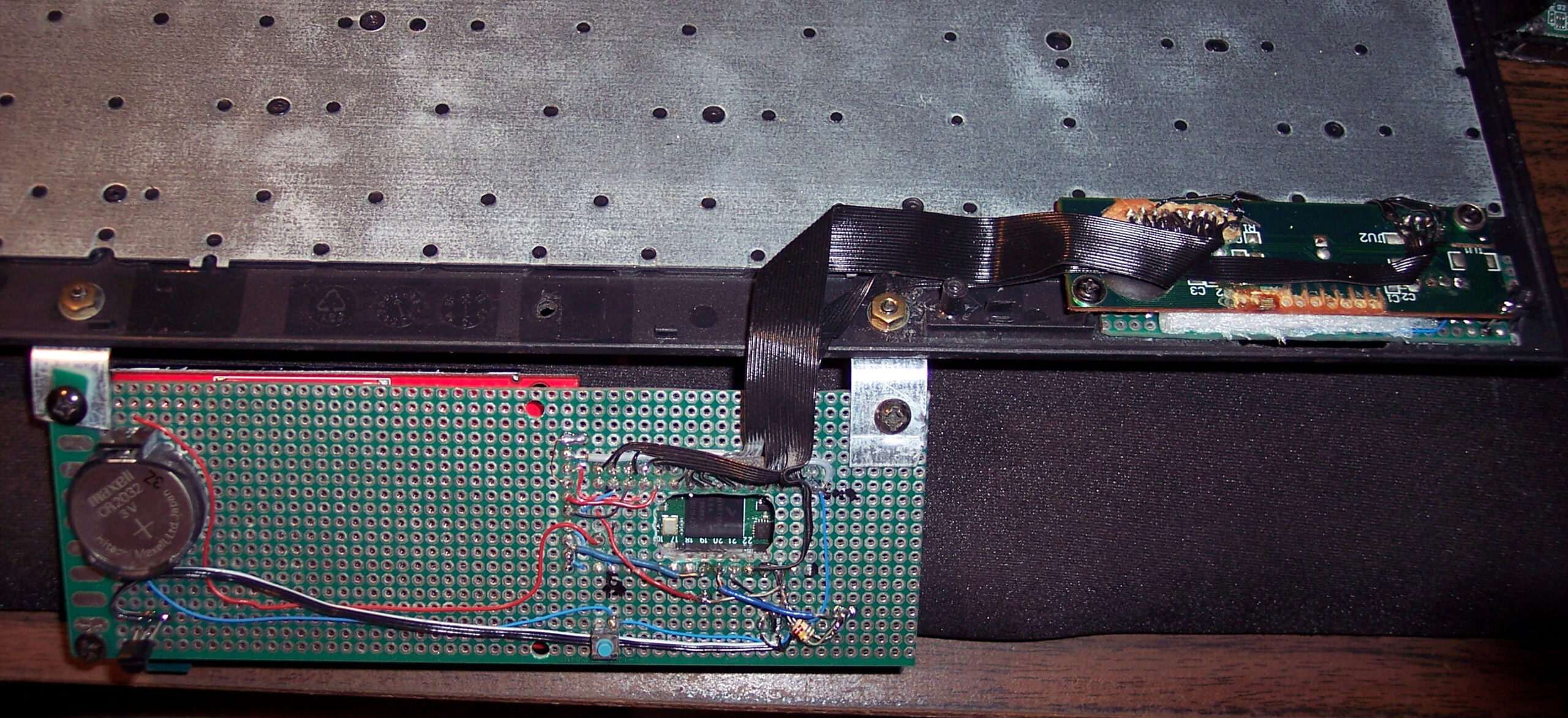
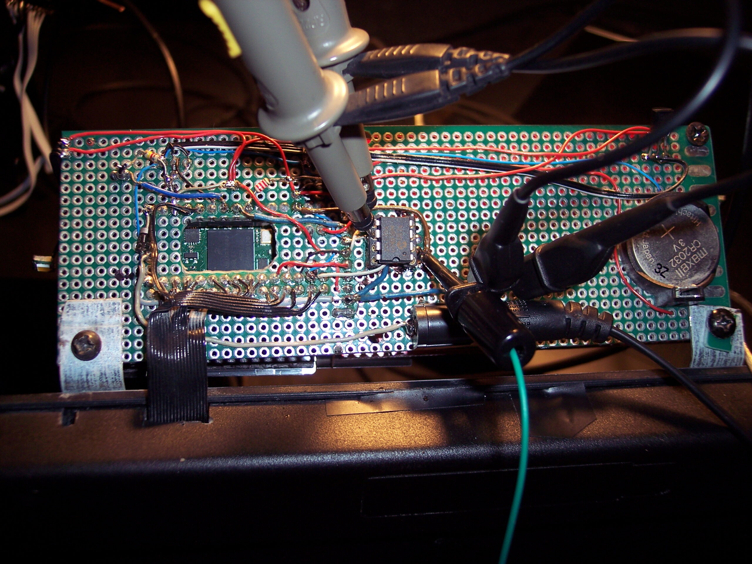
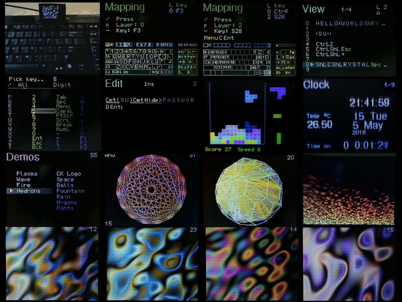
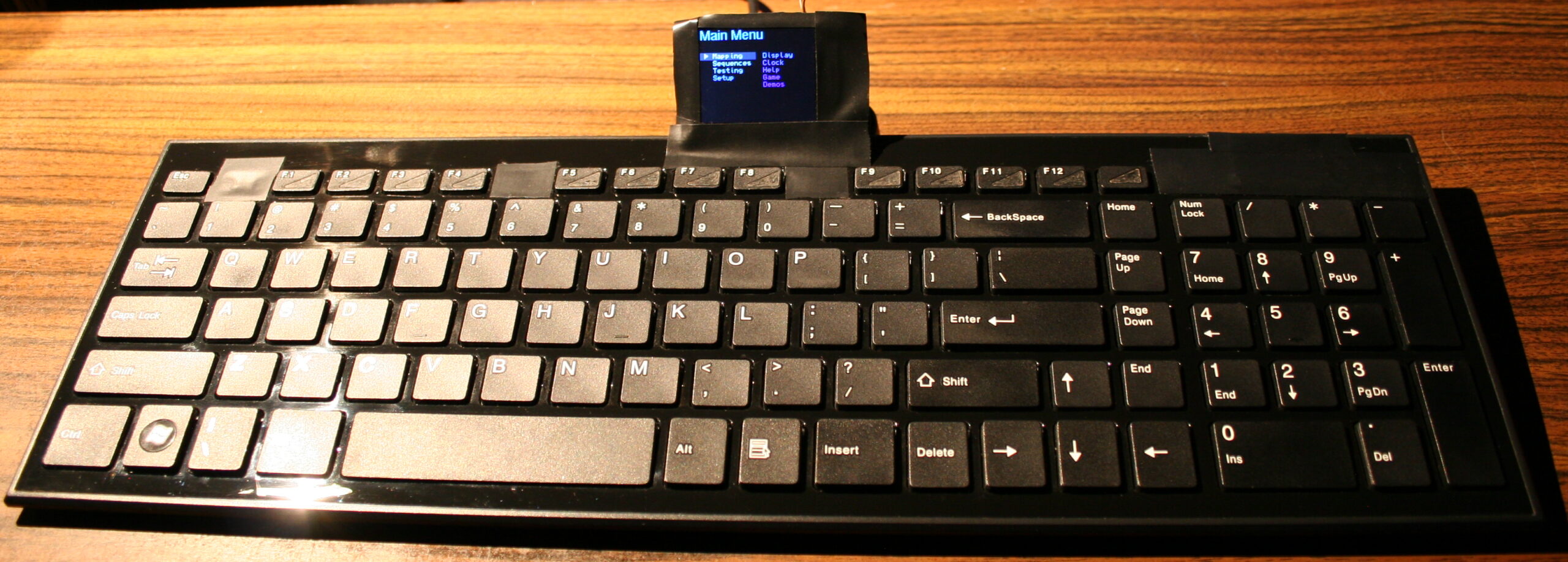
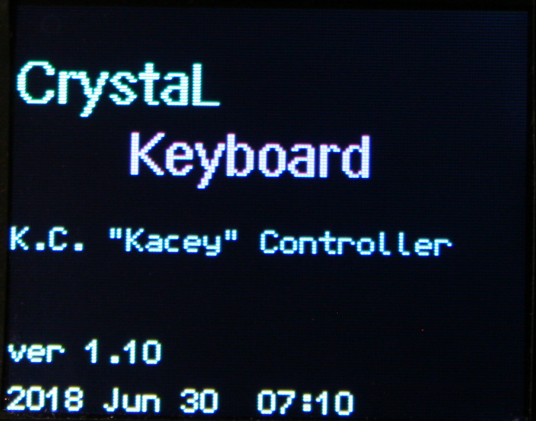
This is my newest keyboard controller software (based on my previous one) used in my keyboard CK9 (upgraded CK6), running on Teensy 4.0 with a 2.8″ color LCD display (320×240, ILI9341 chip). It allows editing everything like key mappings, layers, sequences/macros in real time on its display (was already in previous one).
▶️Videos
Here are videos of keyboard CK9, showing most of K.C.4 on its display:
View – Short video of keyboard and closeup at display.
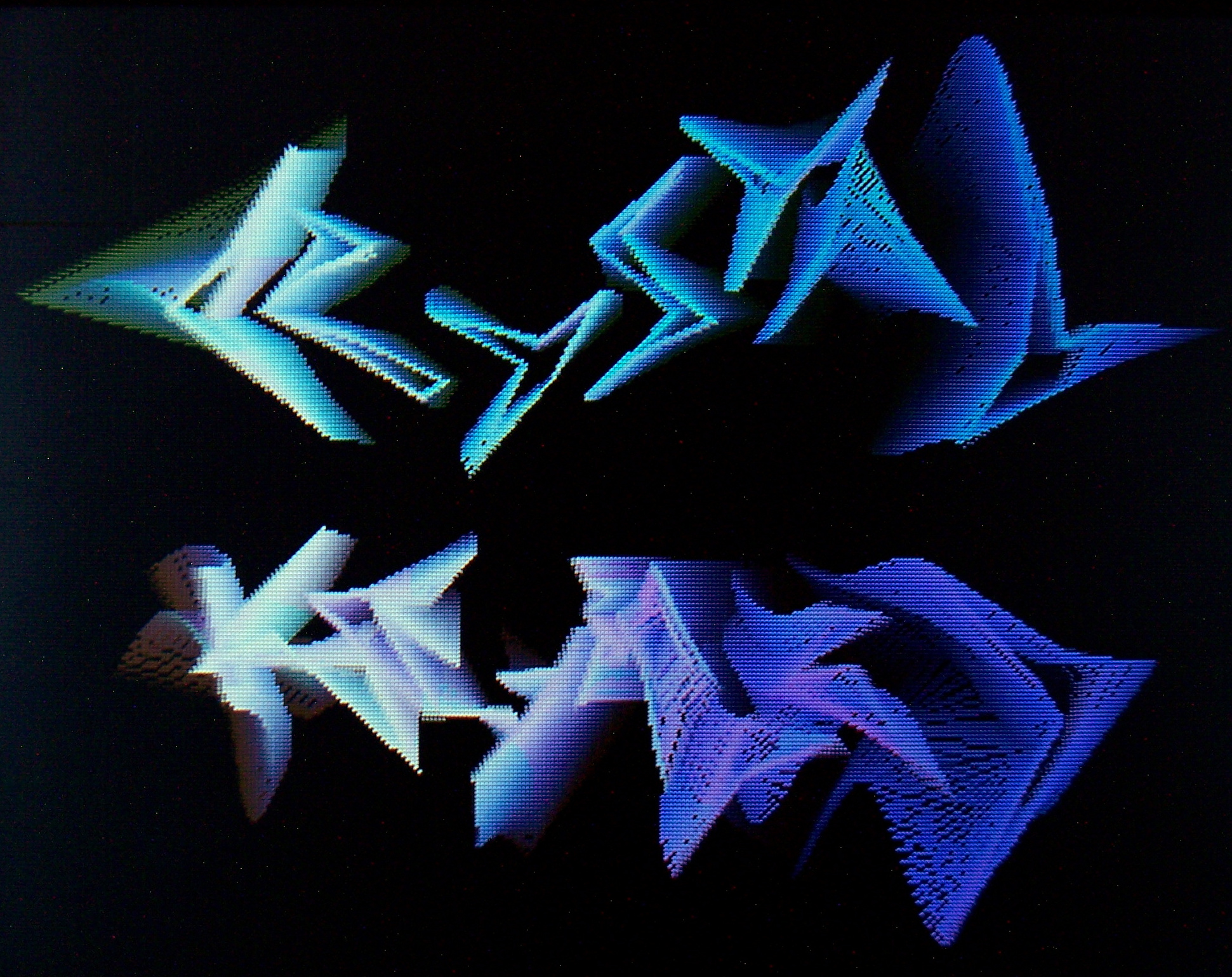
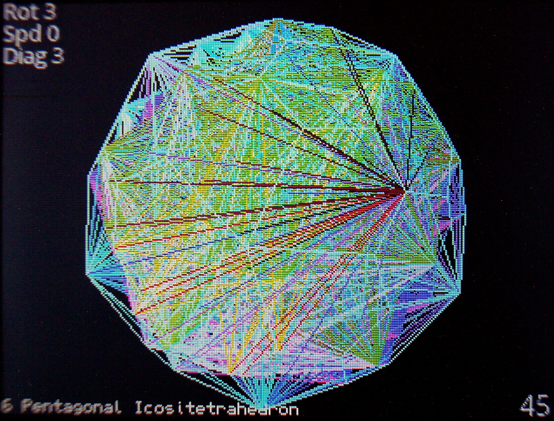
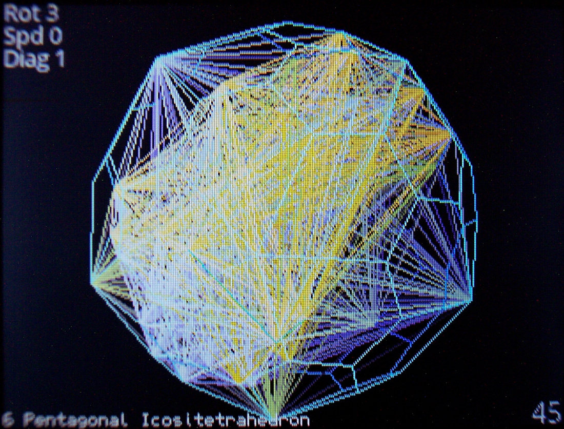
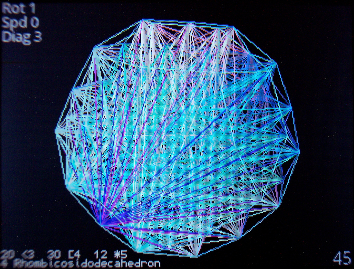
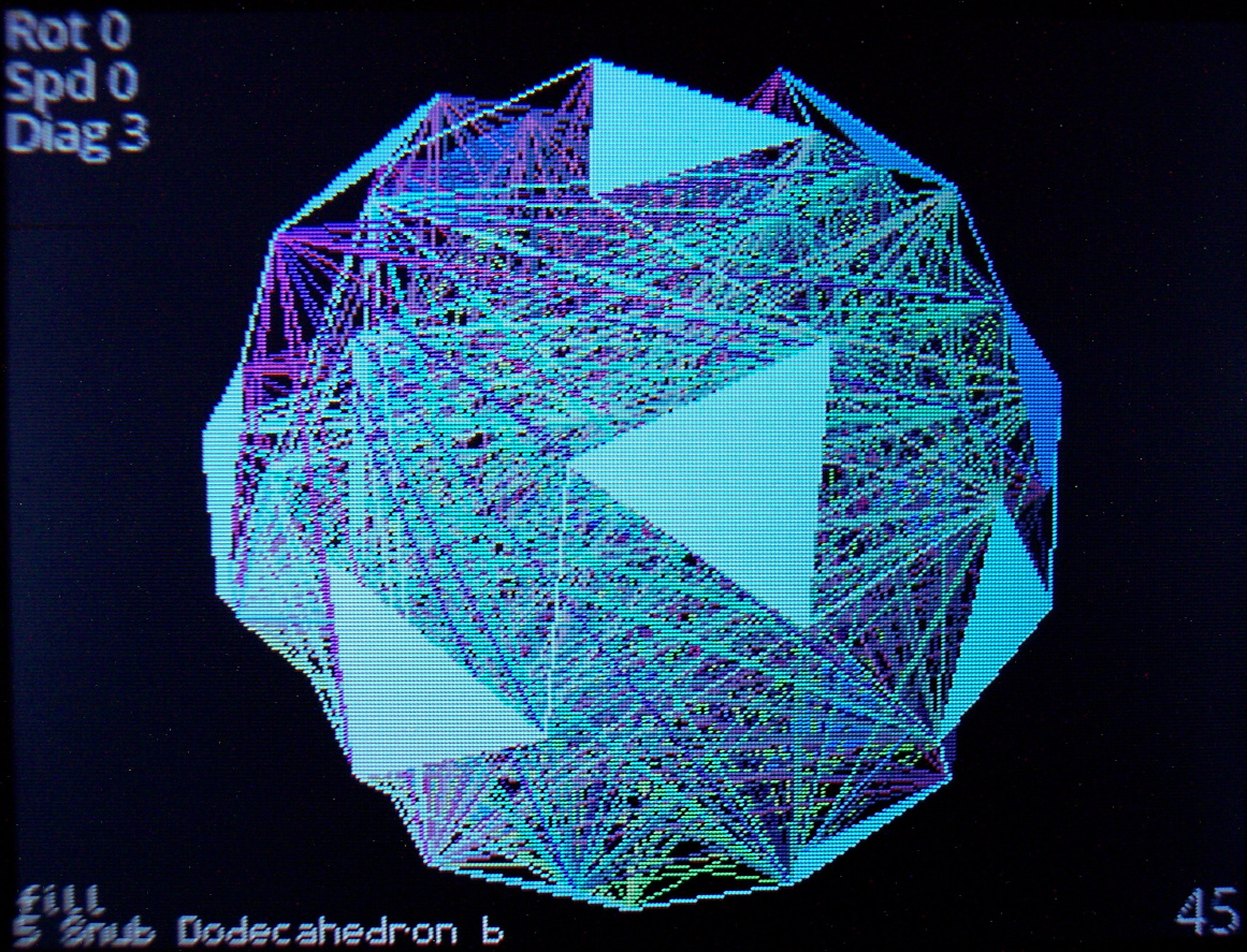
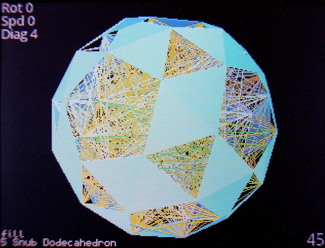
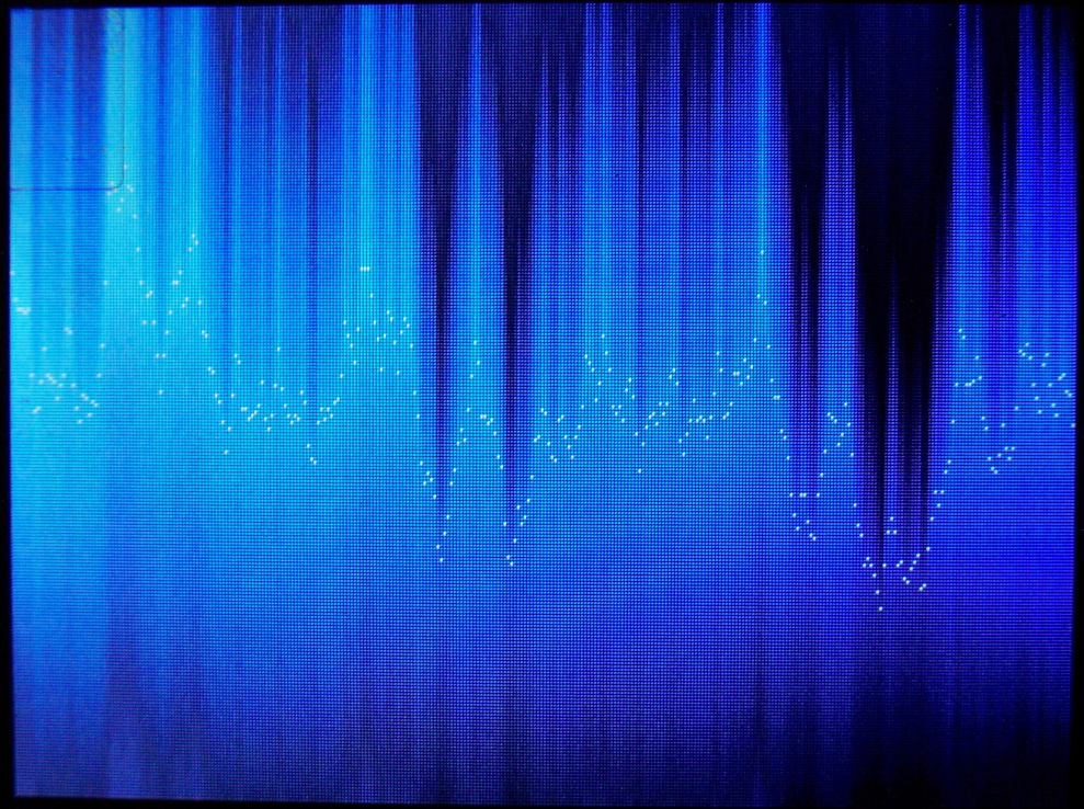
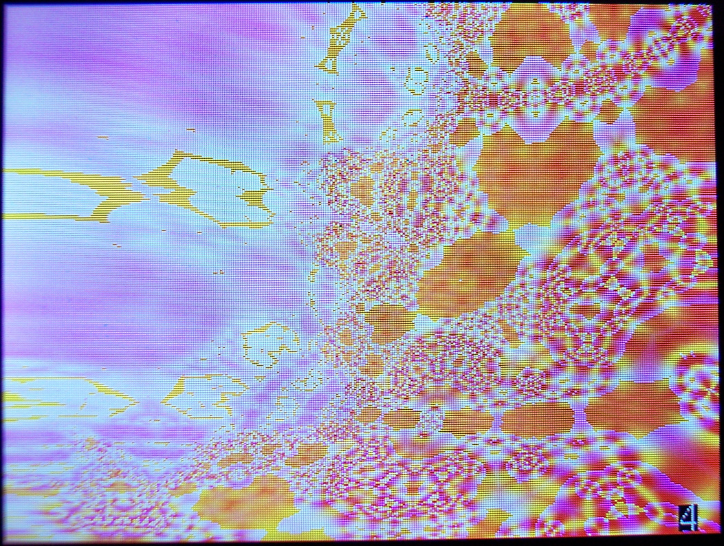
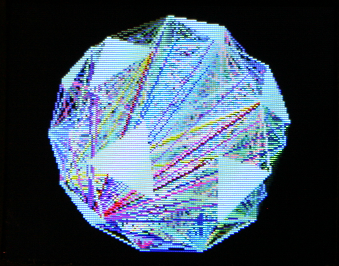
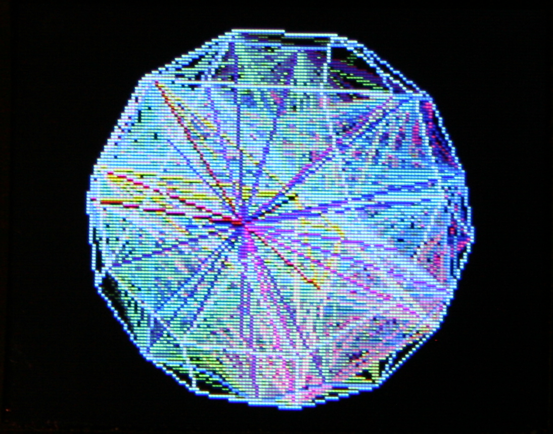
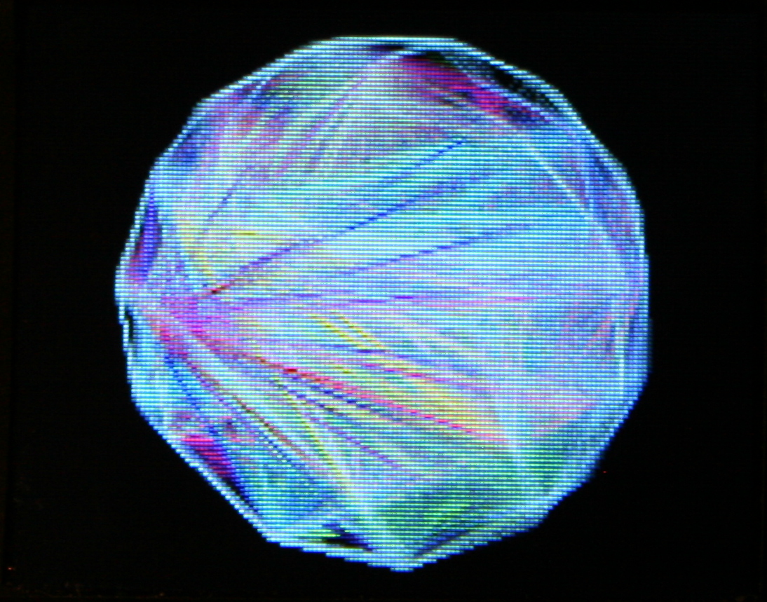
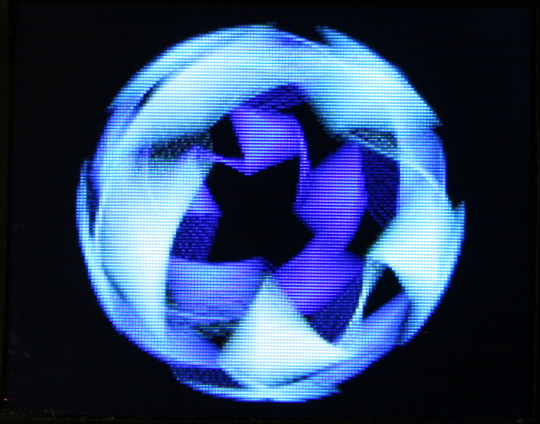
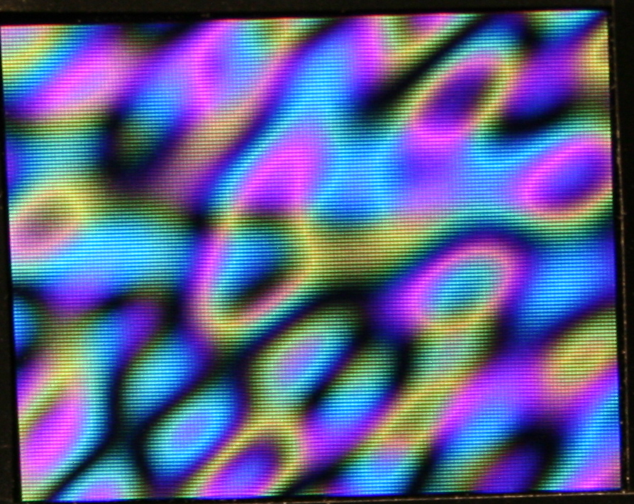
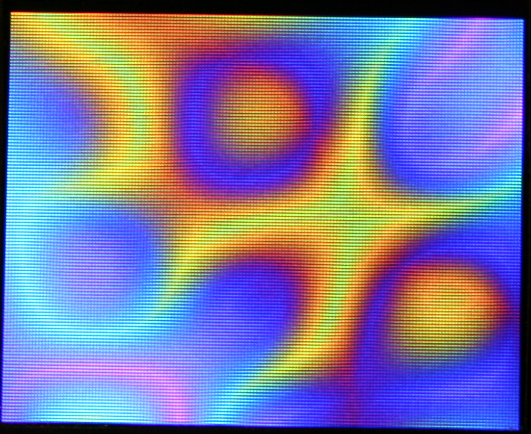
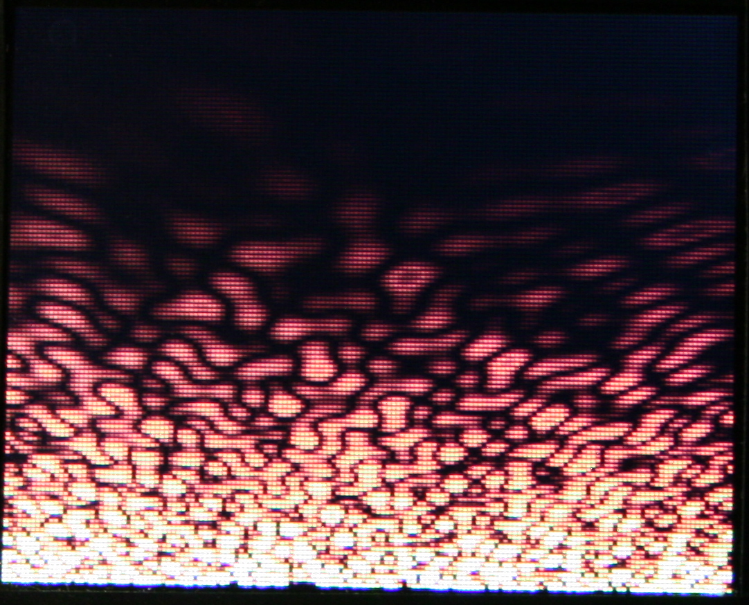
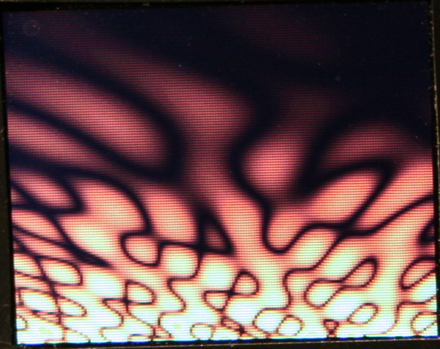
Demos – Showing all demos (in auto mode): Plasma, 3D Polyhedrons with diagonals, Wave, Fire (meh), 2D waving CK Logo with shadow, and old Rain.
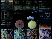
Features – A detailed look at features, no voice or commentary though. Editing mappings, sequences, testing etc.
Link to my channel with all keyboard videos so far here.
📂Sources
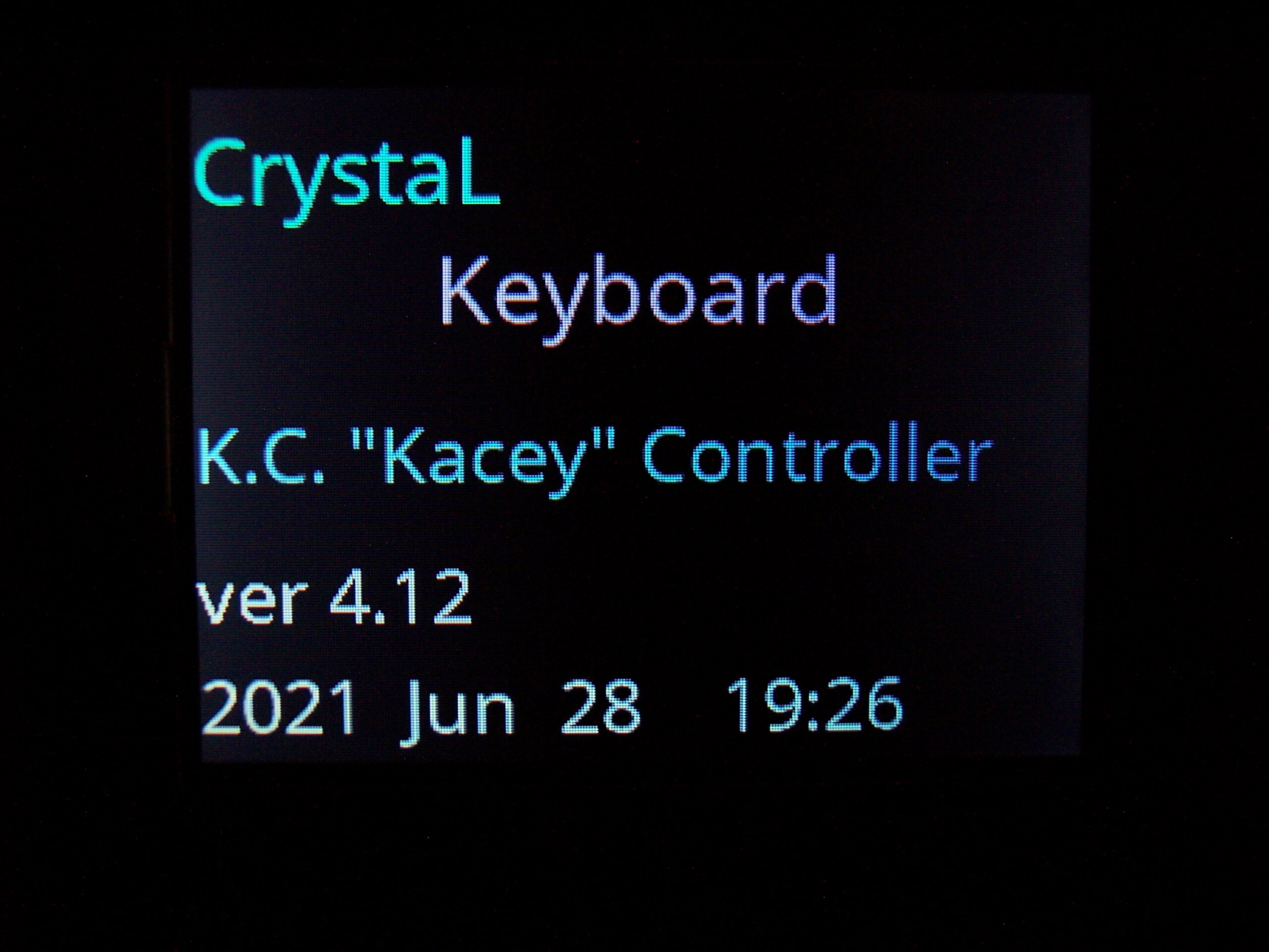
My firmware sources are here. It’s called K.C.4 (“Kacey”) simply from Keyboard Controller and 4 from Teensy version.
The readme with all key features is visible on github. Here is more practical description. At end of page I wrote a comparison from my previous version (for Teensy 3.2) and quickly with other controllers / keyboards.
📊Features
The current code features are (and were mostly present in my previous K.C. version):
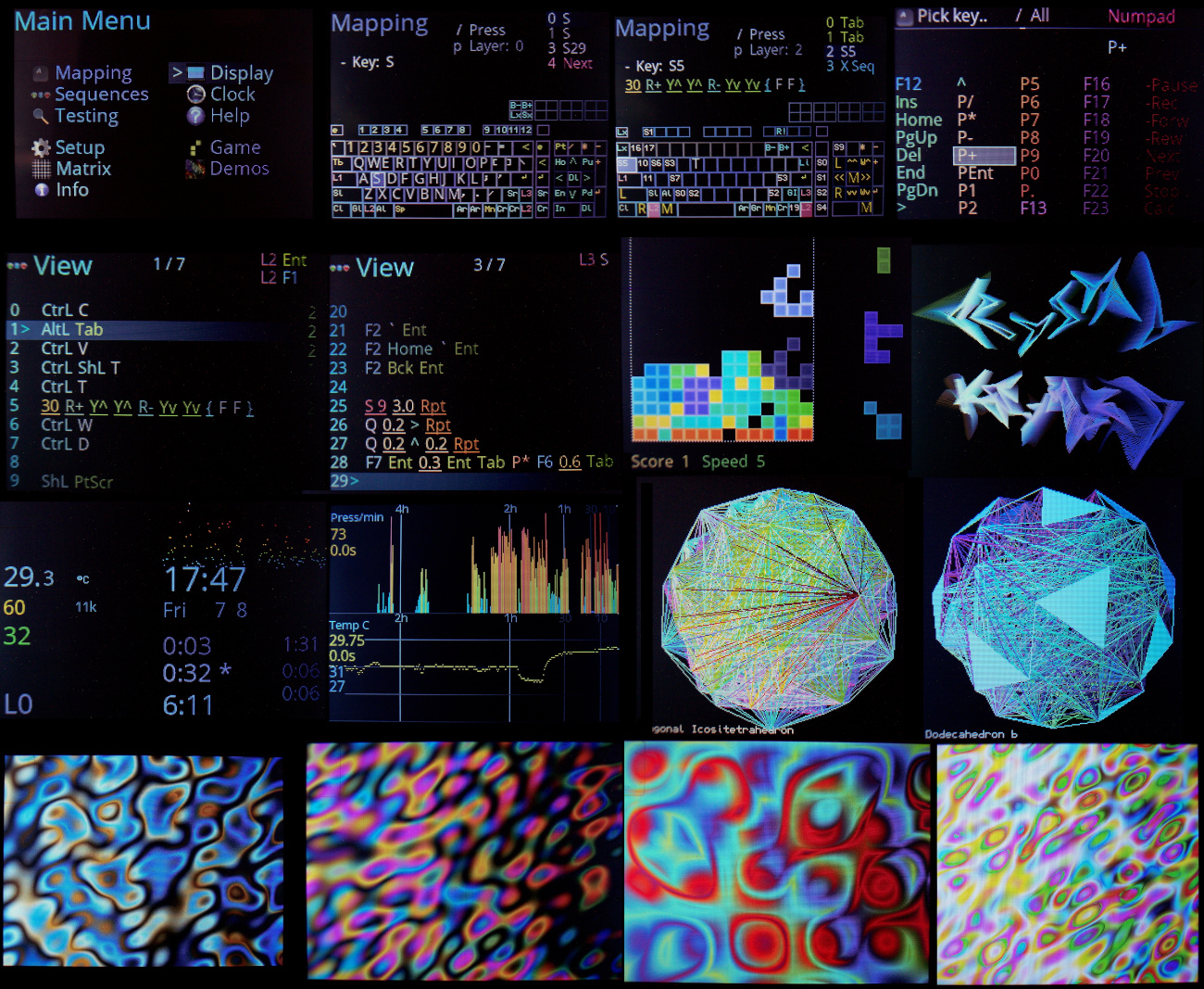
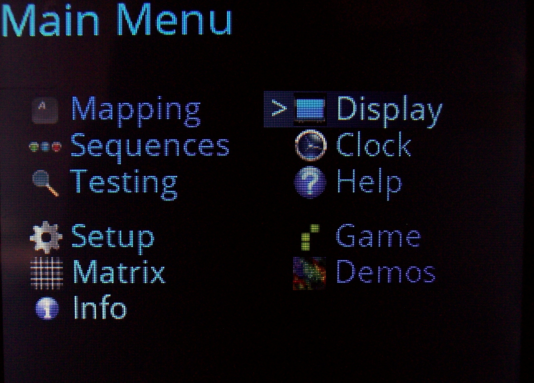
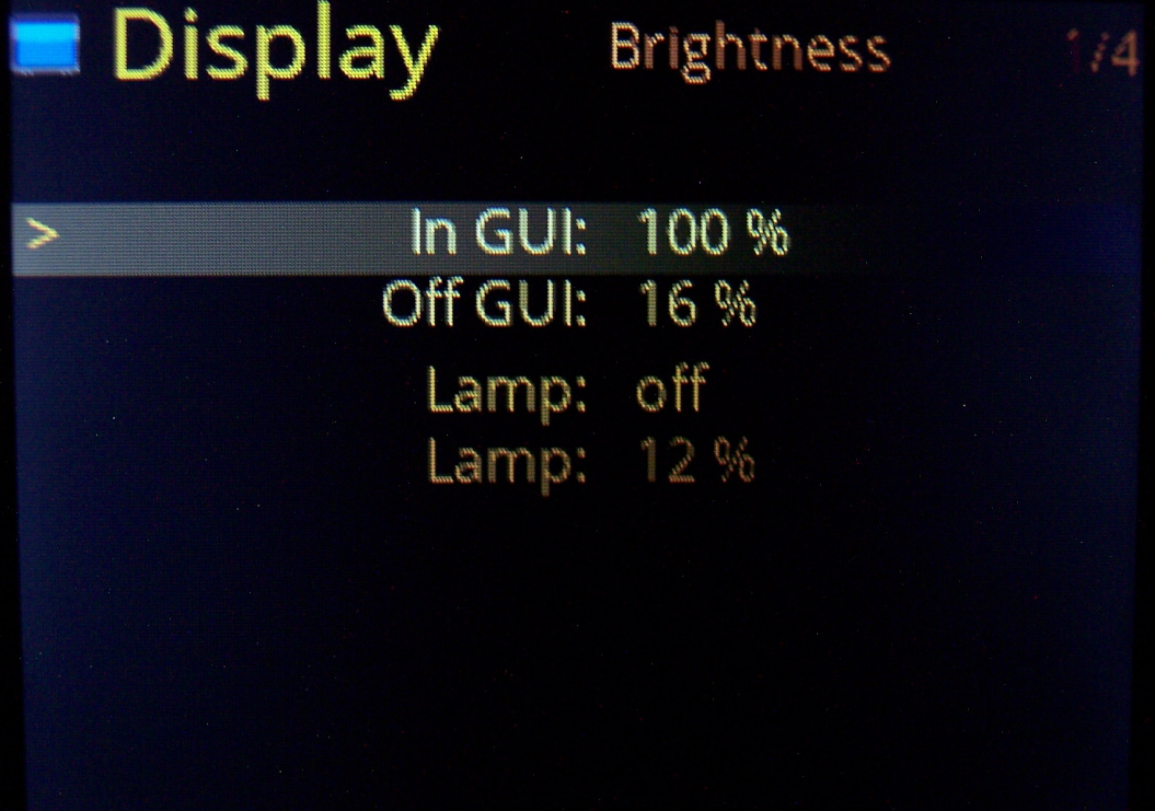
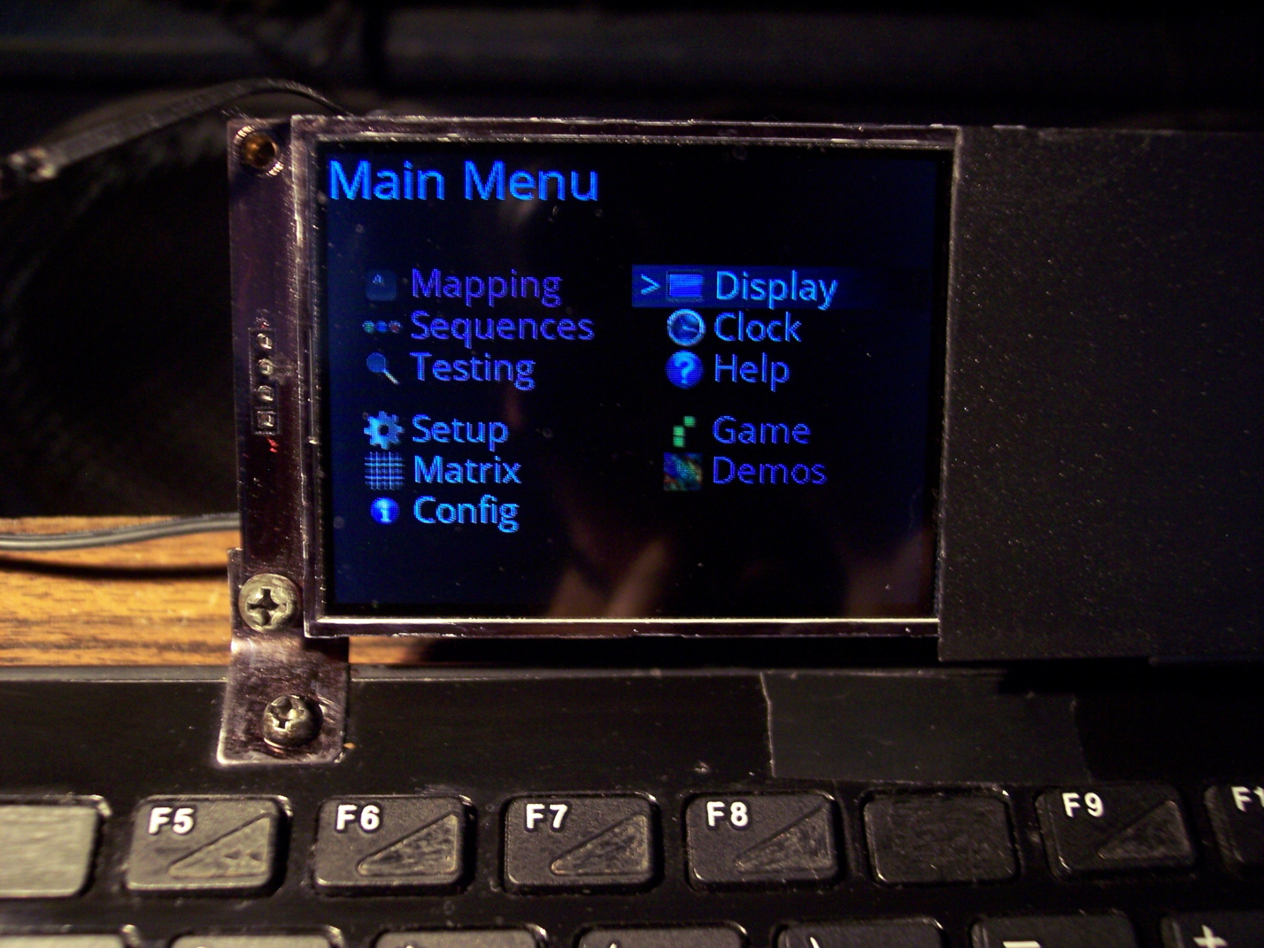
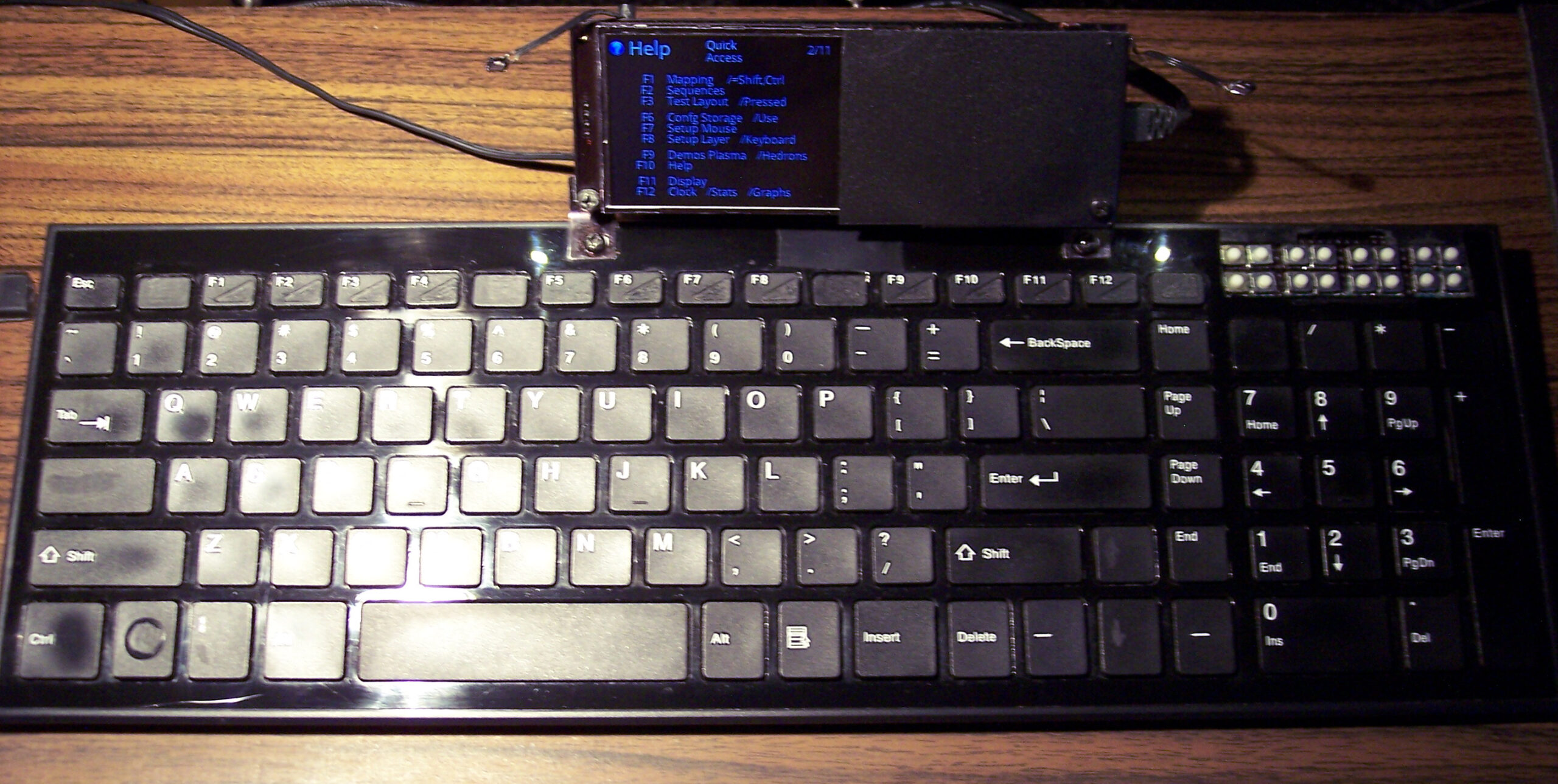
🪟Display
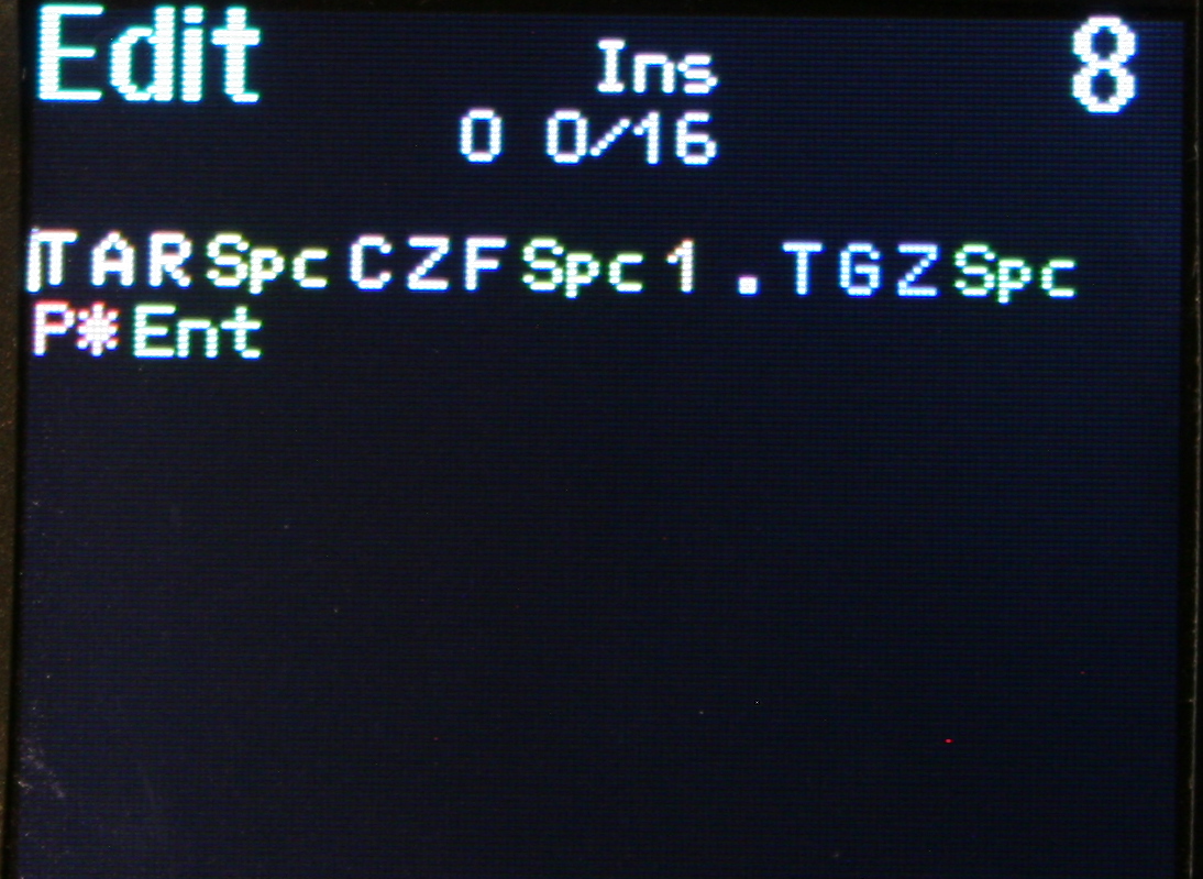
With menu, where you can edit everything possible.
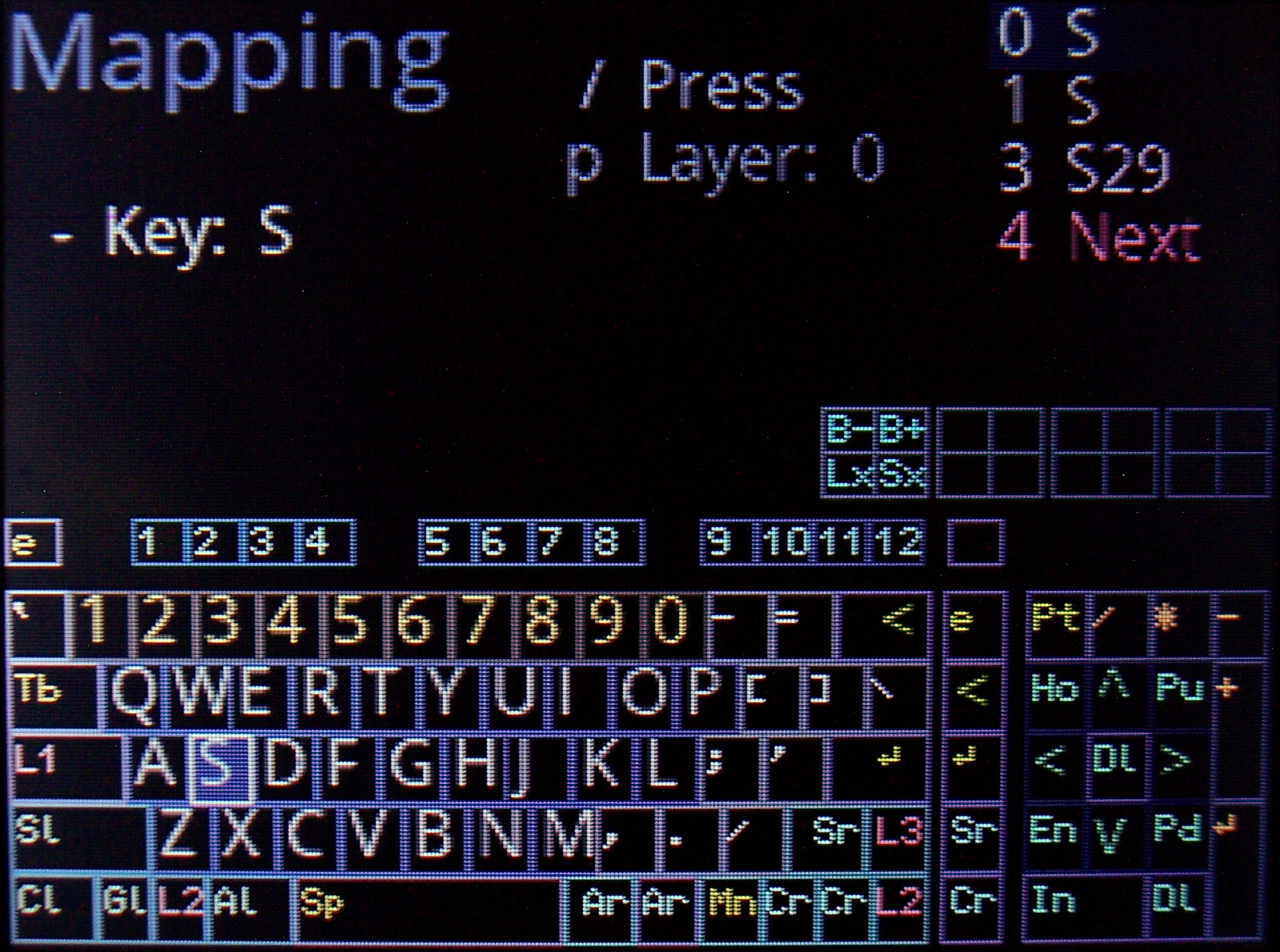
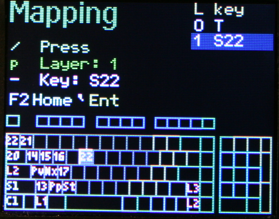
🔠Mapping (key binding)
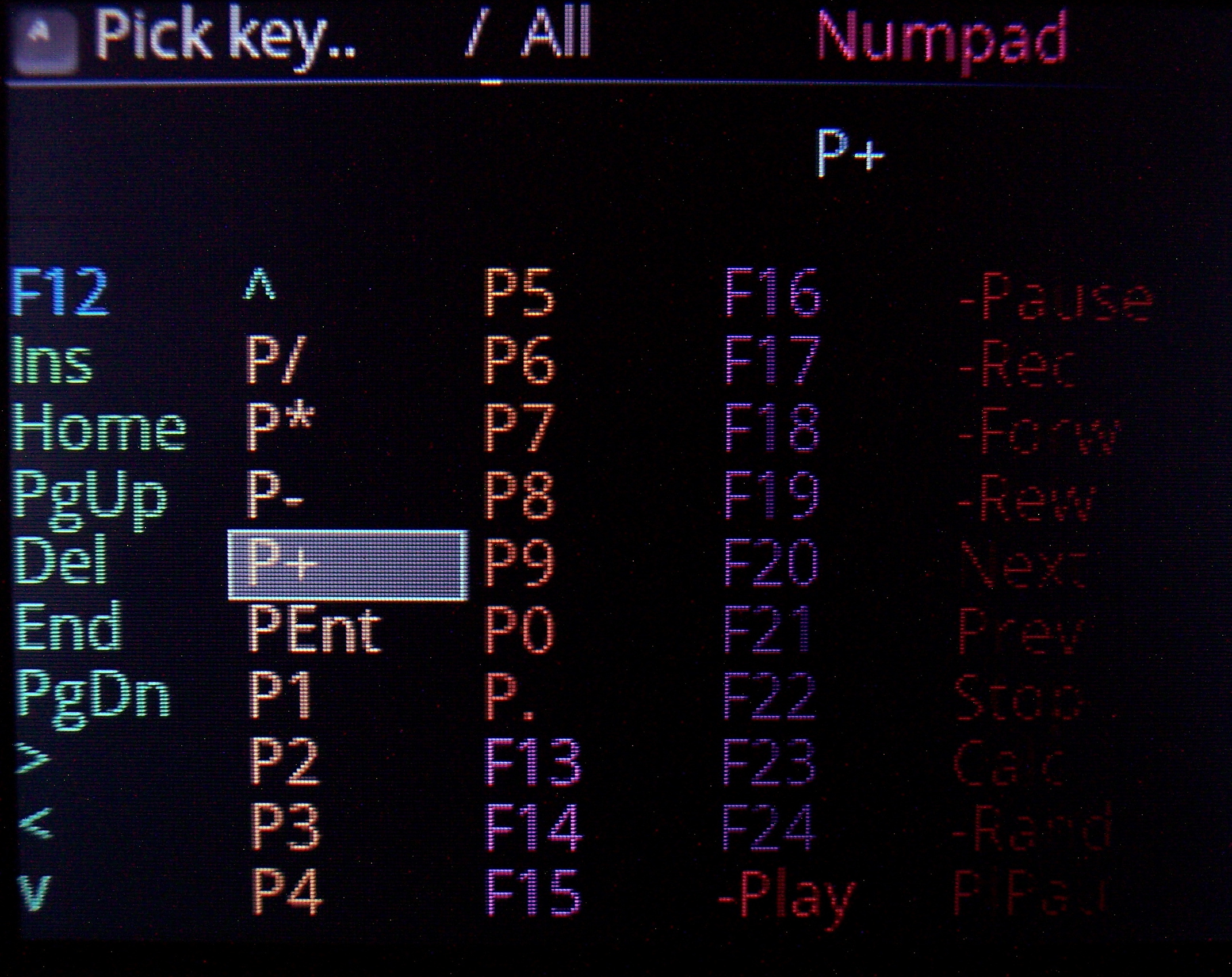
So which USB code will the physical key send to PC when pressed. There is a pick list with all common keys (and internal functions, sequences, etc) to choose from when binding. It has group colors and group filter for easier orientation.
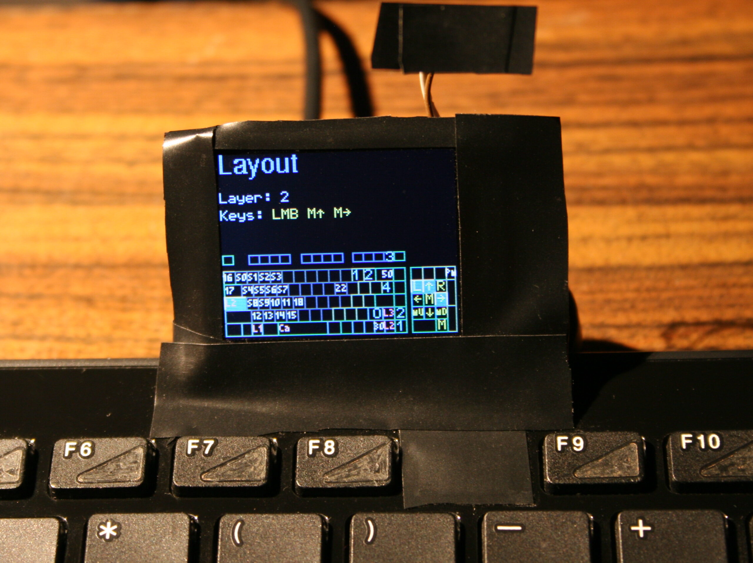
⌨️Keyboard layout
Drawn on display. Shown when editing mappings (for currently chosen layer). Has a cursor to move around between keys. It’s also possible to jump to a key by pressing it.
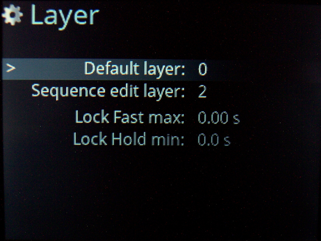
🧮Layers
If you hold a key, whole keyboard layout changes giving you other keys. Kind of like the Fn keys on laptop but much more useful and customizable. A common feature of custom controllers. Locking layers is also possible, either by lock/unlock key, tapping layer key fast or holding it for longer. Of course can be disabled and delay parameters are changeable.
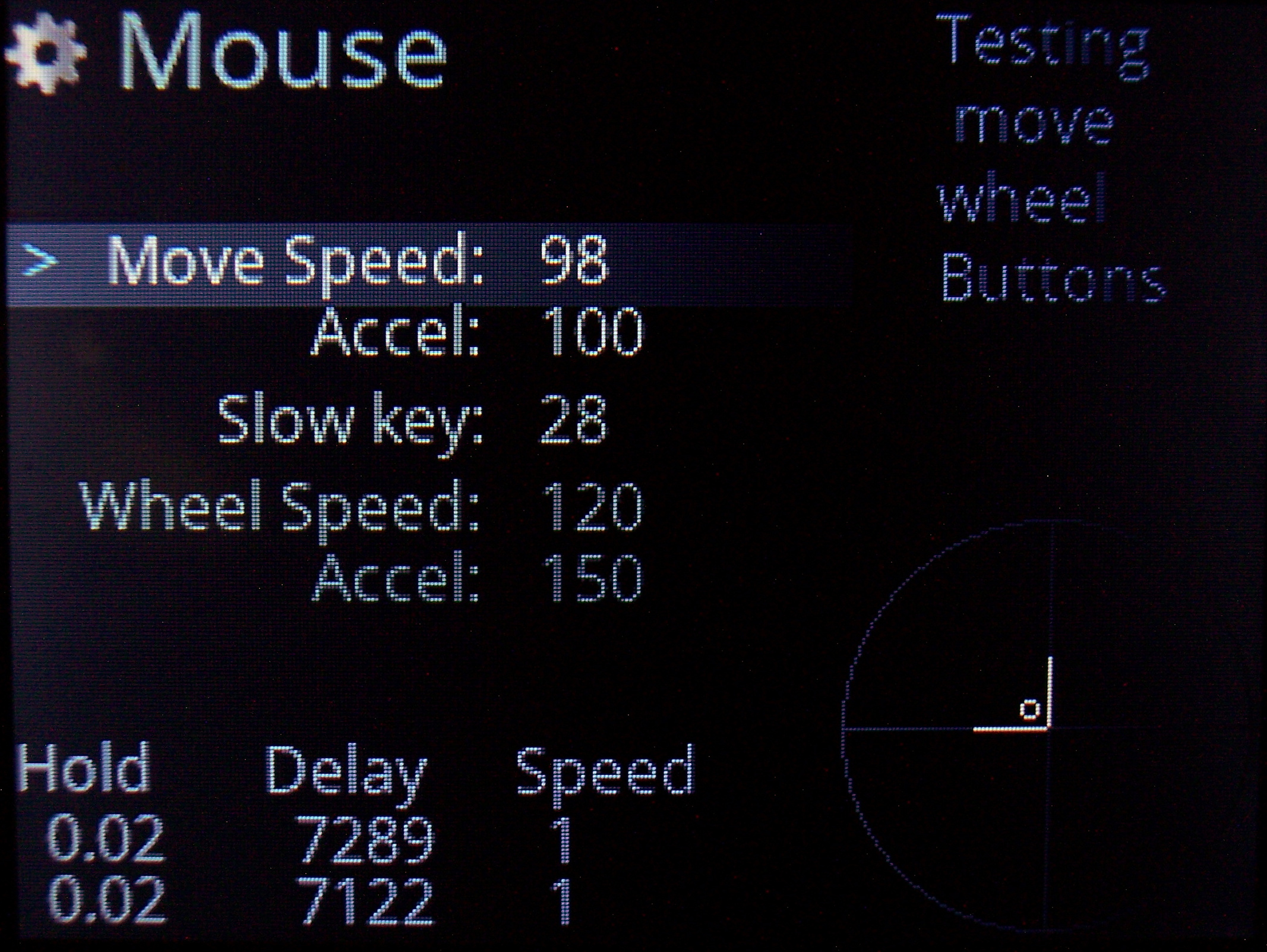
🖱️Mouse keys
Keys that will move mouse, press mouse buttons or scroll mouse wheel. Also featuring acceleration with parameters for it and speed in GUI.
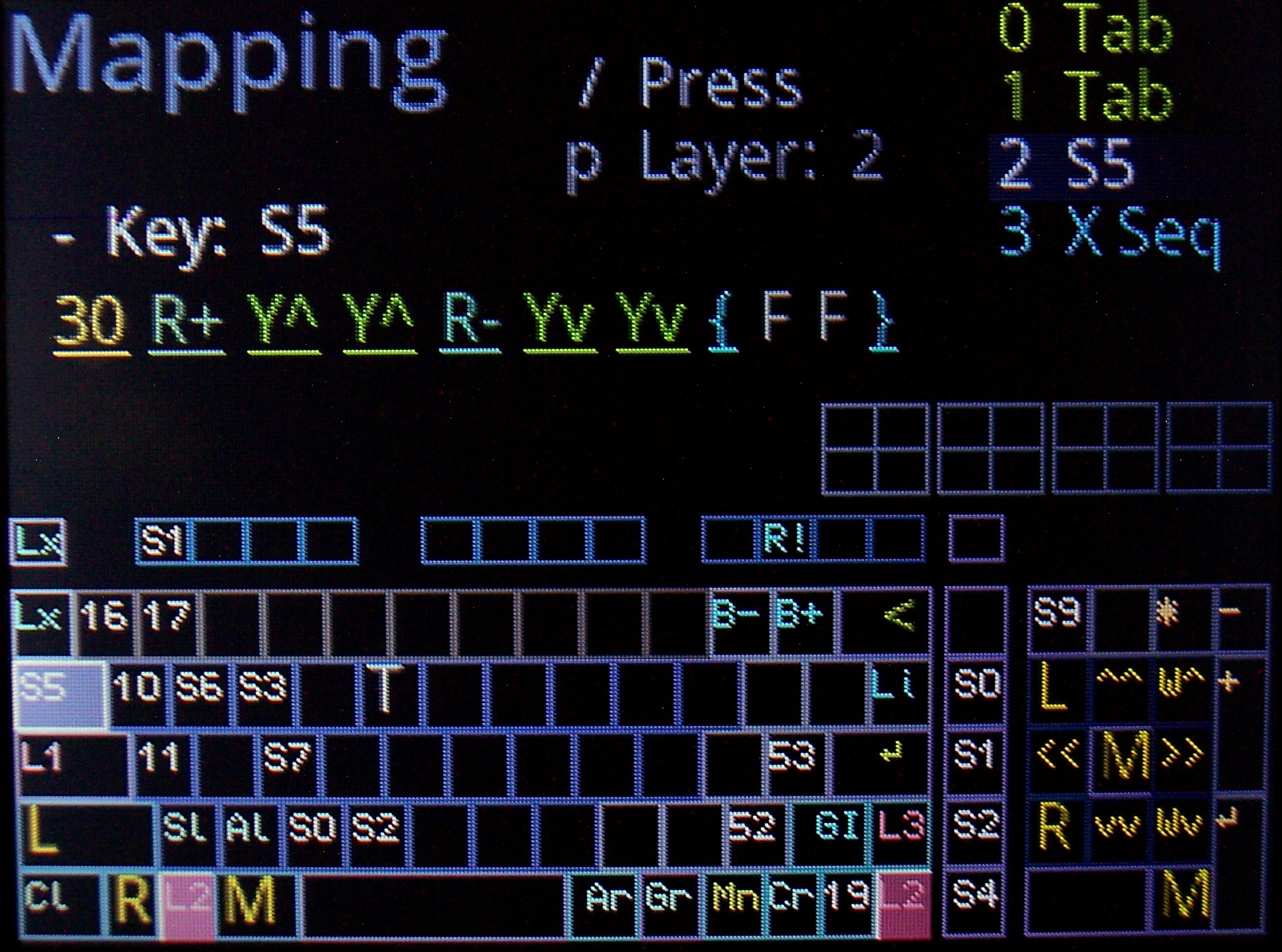
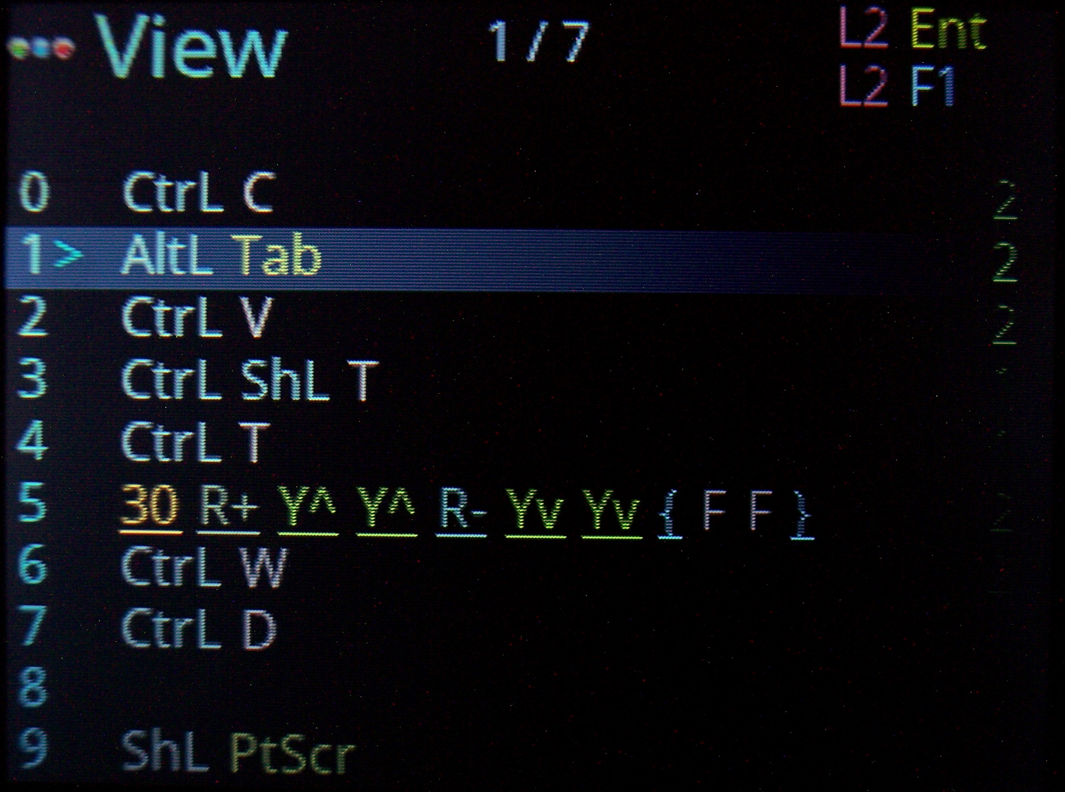
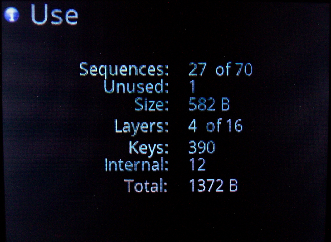
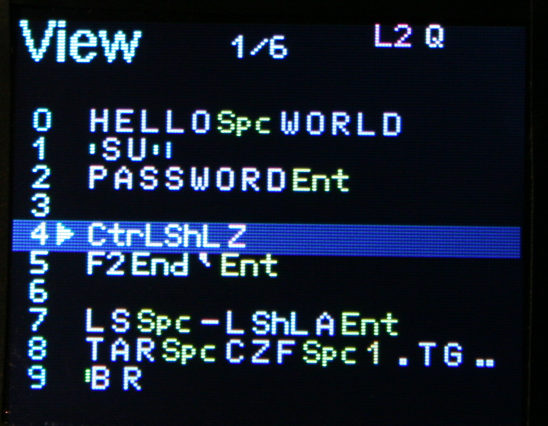
🔤Sequences aka Macros
Basically any key combinations (for key shortcuts) and any sequences of key presses (for e.g. passwords). I am showing sequence previews where possible too, so when editing Mappings (for a sequence key), when picking a key from list or Testing pressed keys (if a key runs a sequence). I am also showing in sequences View, all mapped keys that run selected sequence.
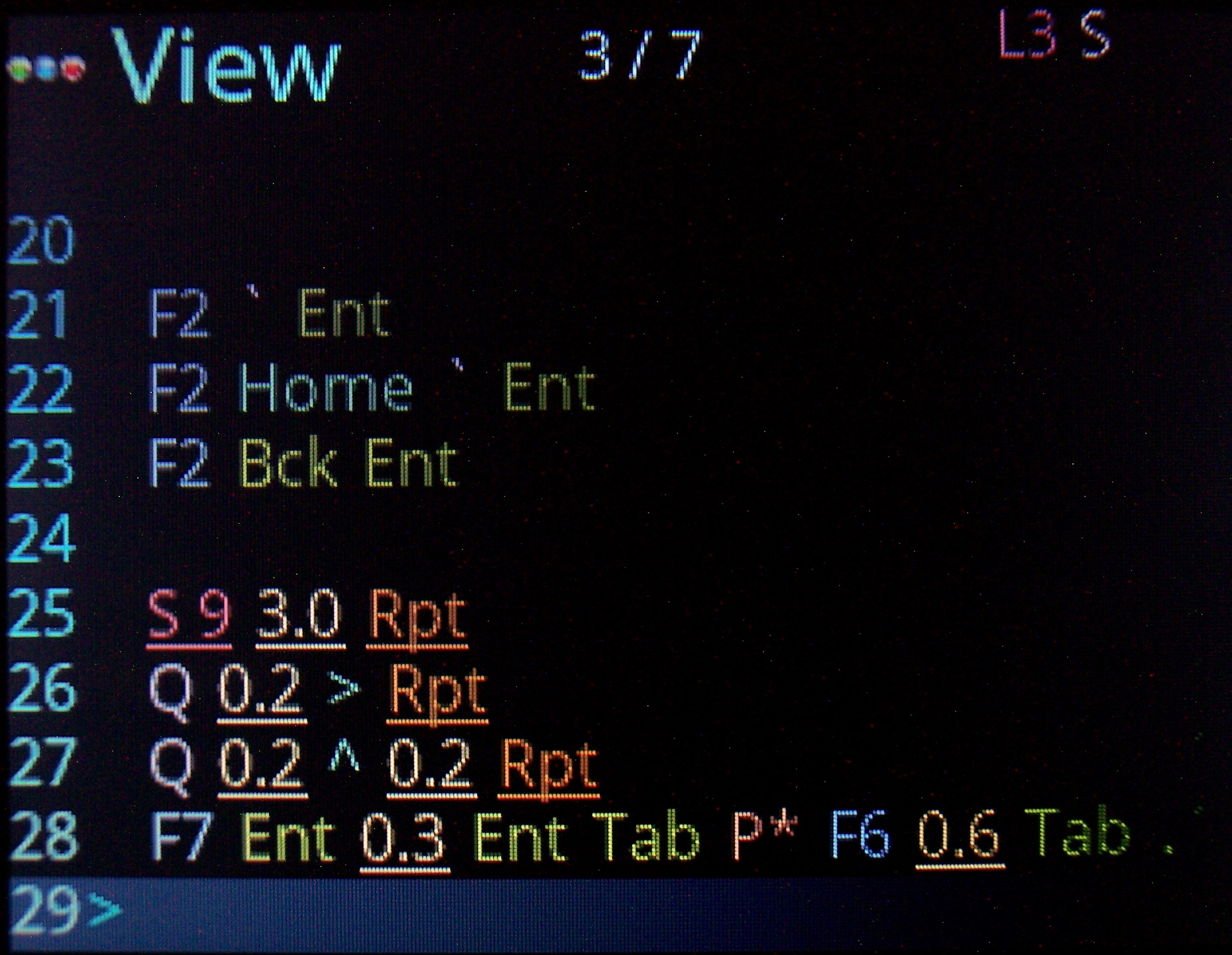
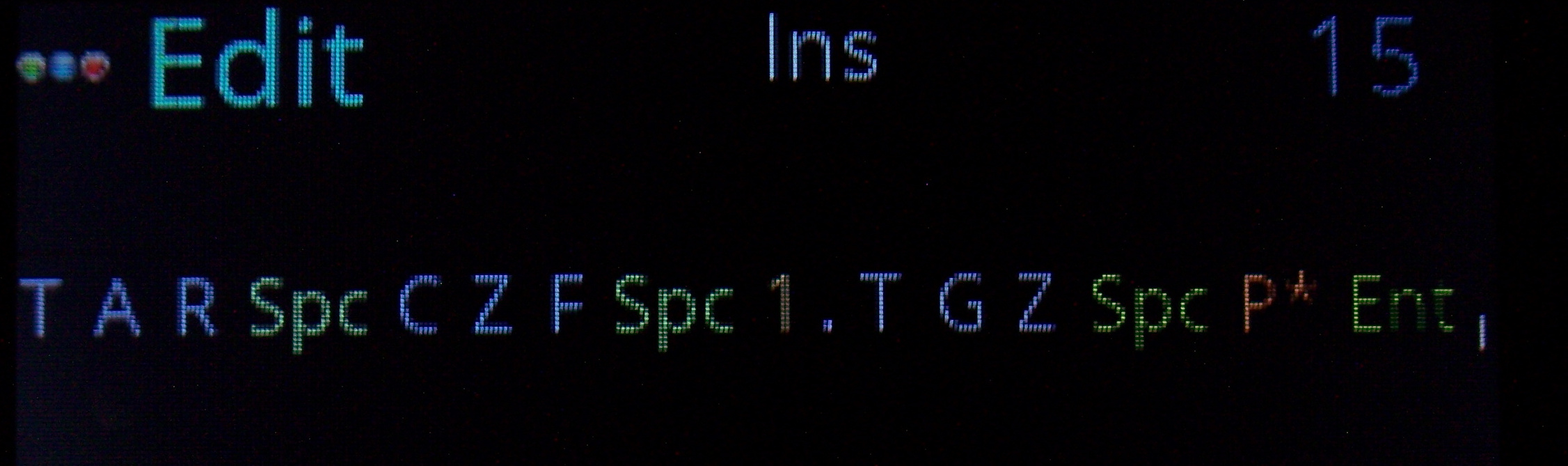
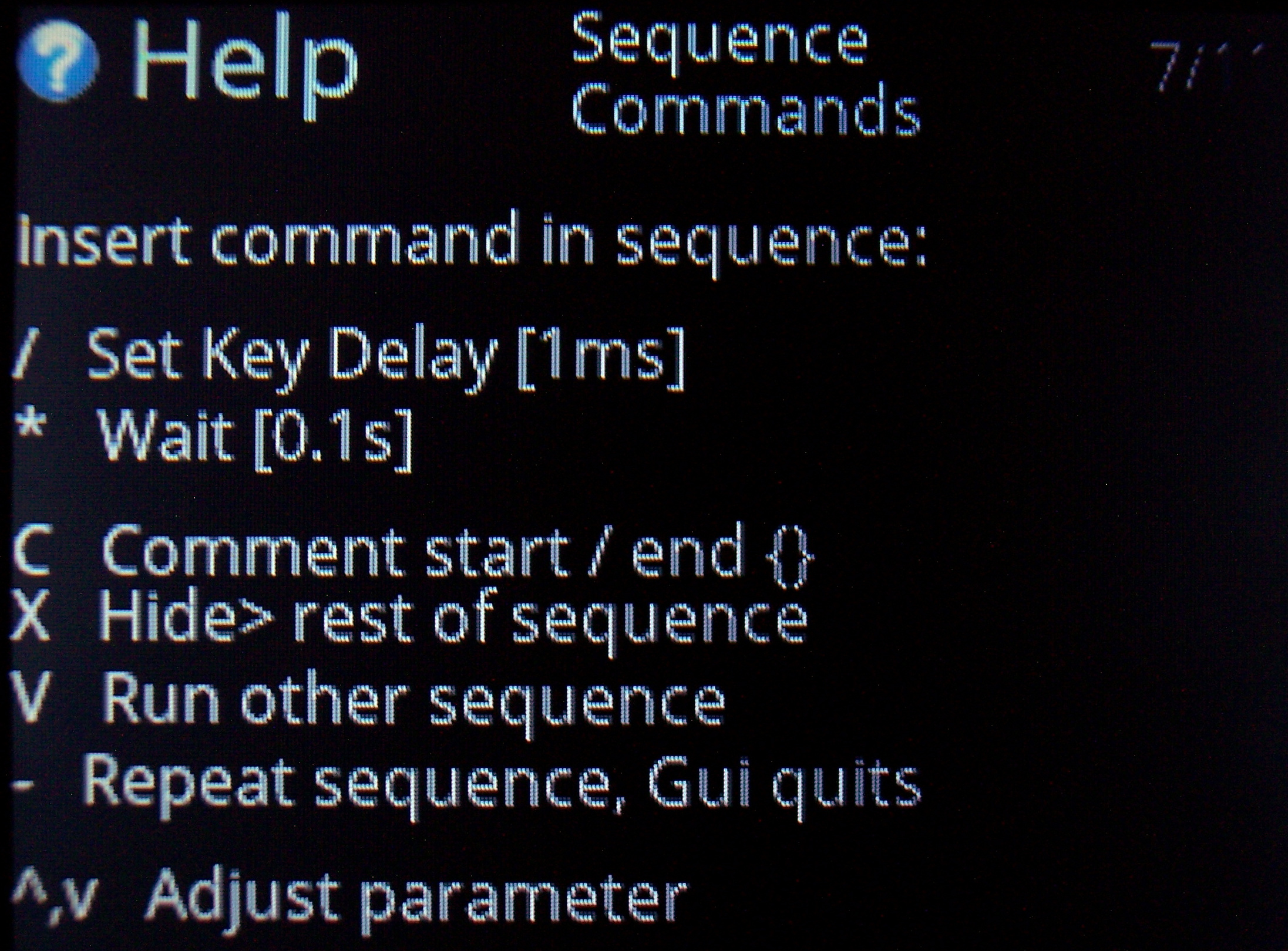
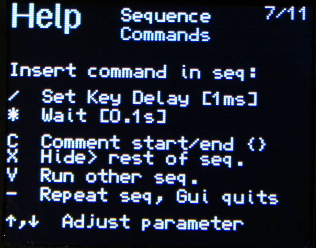
✅Sequence commands
Further extension, these are special commands (beside sequence keys), that e.g. wait for few seconds (0.1s resolution), or change how slow the sequence will run (1ms resolution, useful e.g. for putty).
Others allow putting comments (for sequence purpose), and hiding sequence from preview (e.g. for passwords).
There is also a command to run other sequence(s) from this one. Also a repeat command that will do sequence (keys) continuously, until interrupted. This is e.g. useful e.g. if you want to watch a video faster, skipping parts with arrow keys after a short delay or take screenshots while watching etc. Normal keys can be used when a sequence runs too.
All mouse actions are available as commands too. So for example you can press a key (for a sequence) that will press button or move mouse etc. I have this way a mouse gesture done.
⚙️Internal functions
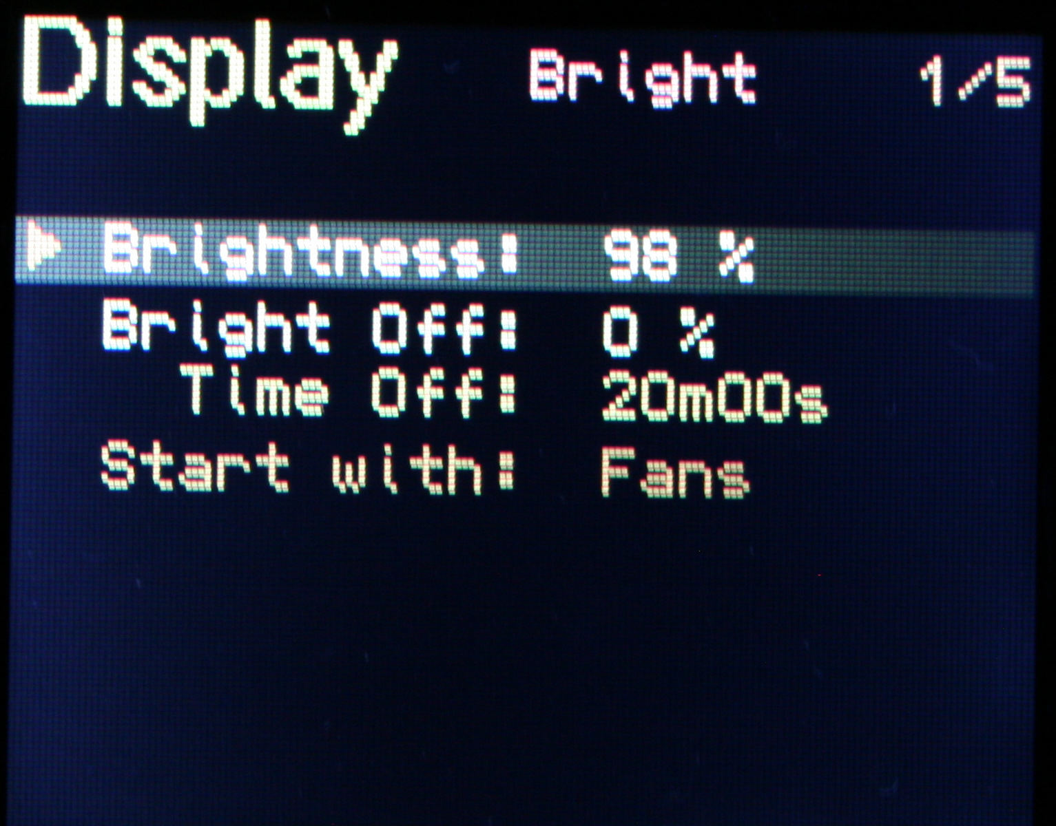
Keys to e.g. dim brightness, toggle GUI, toggle LED light, quit sequence, lock/unlock layer, change default layer etc. This a direct way, faster than adjusting parameters in GUI.
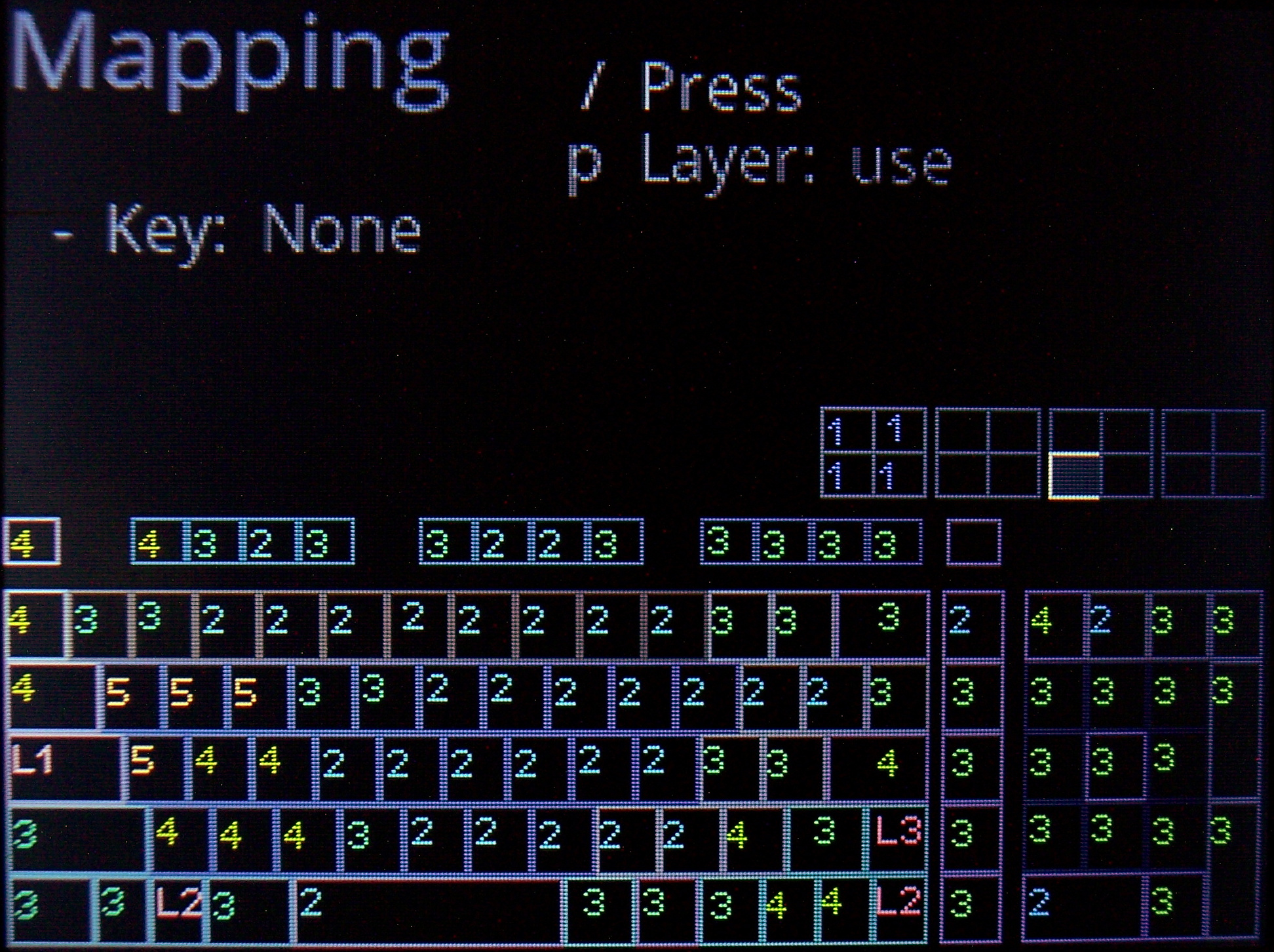
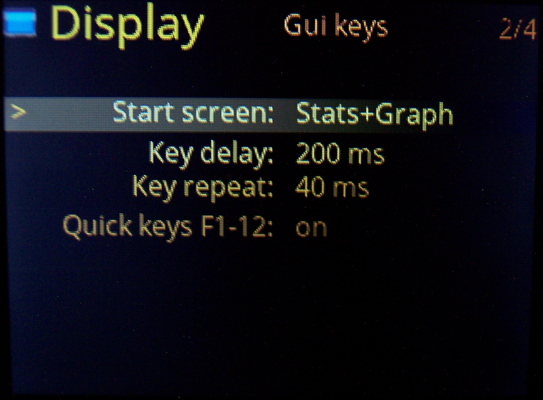
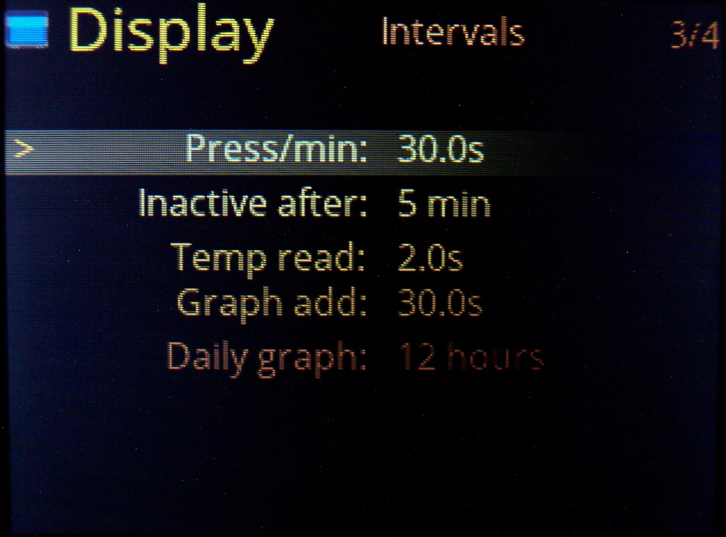
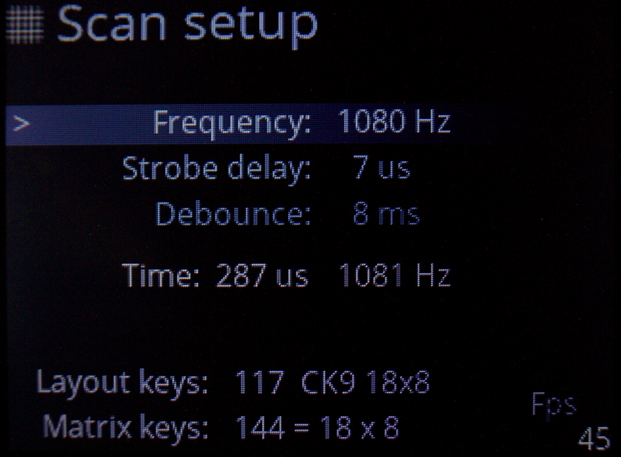
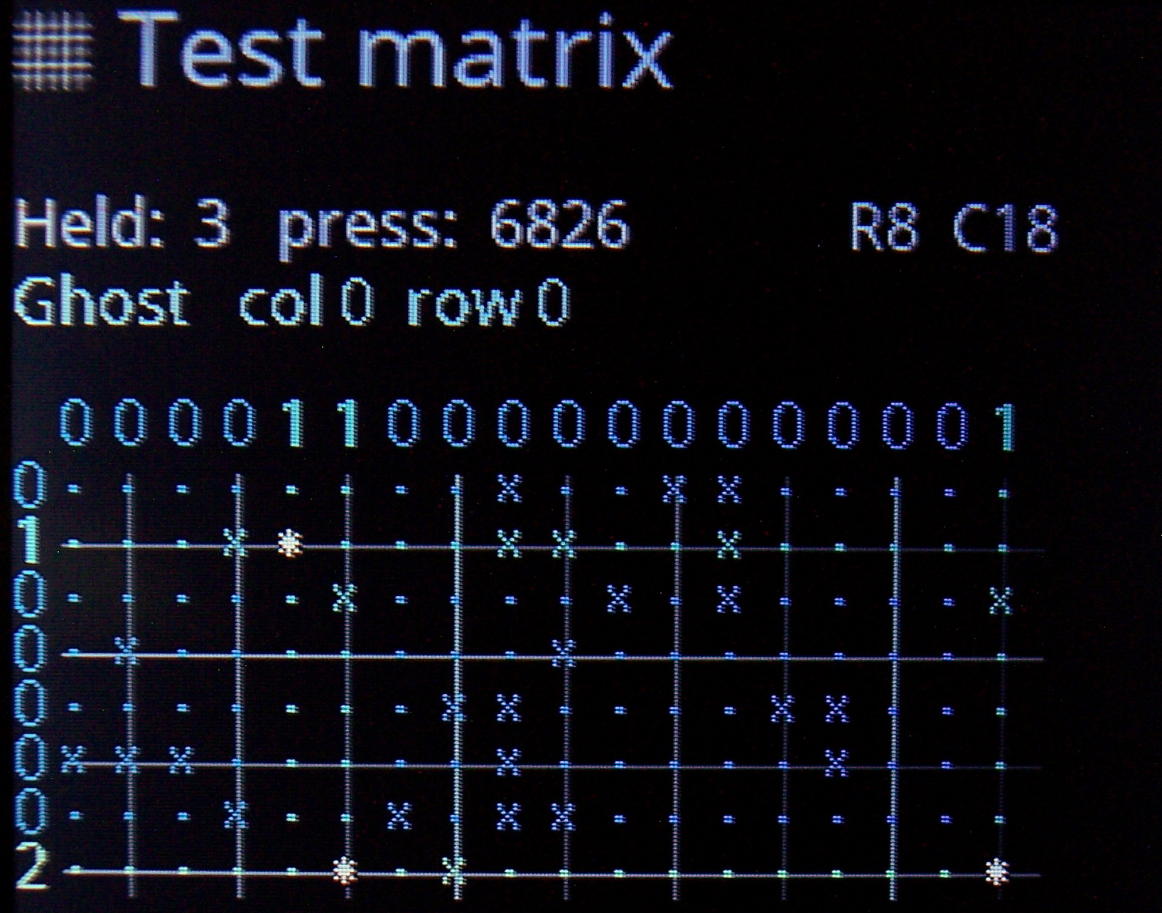
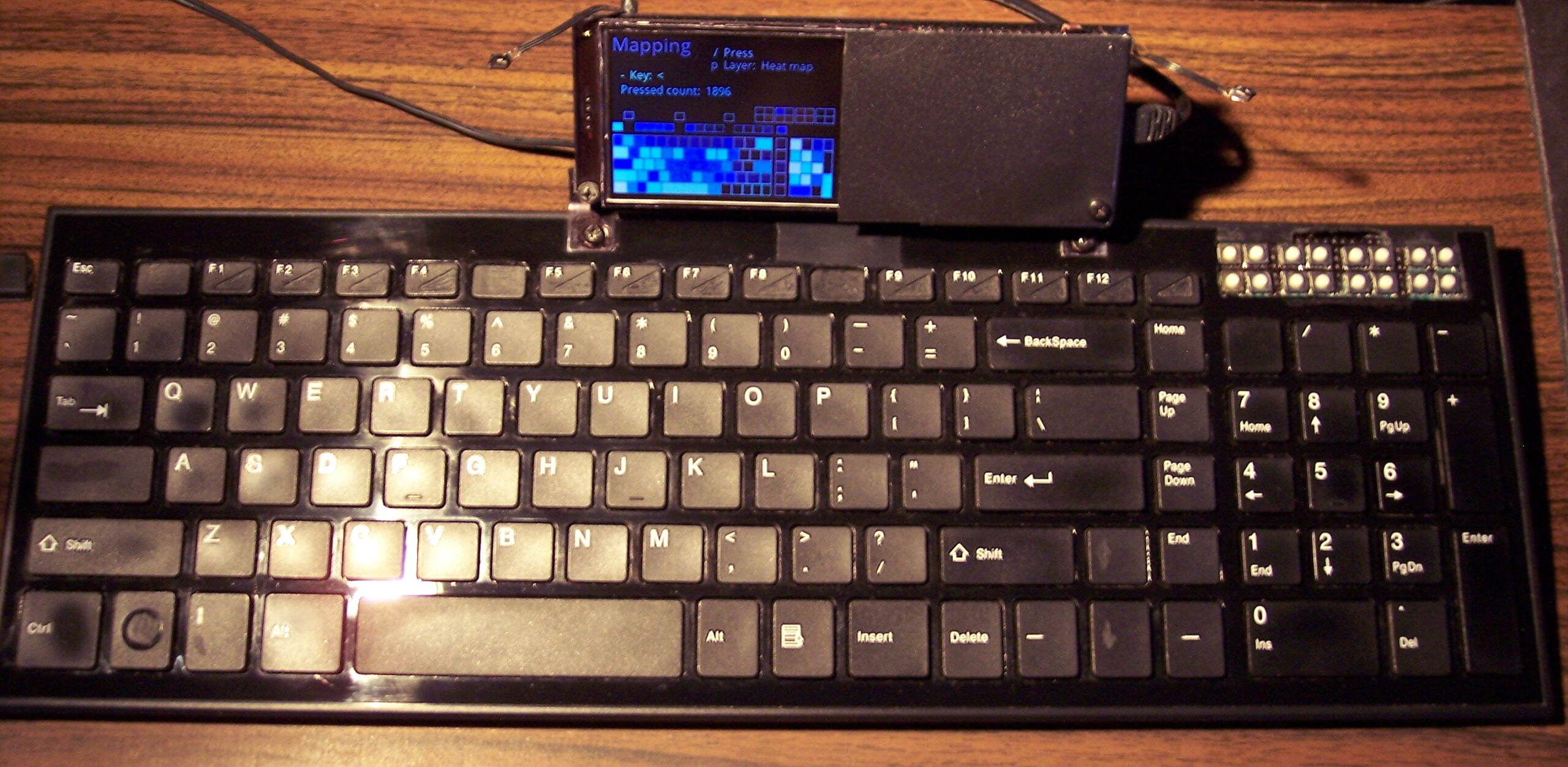
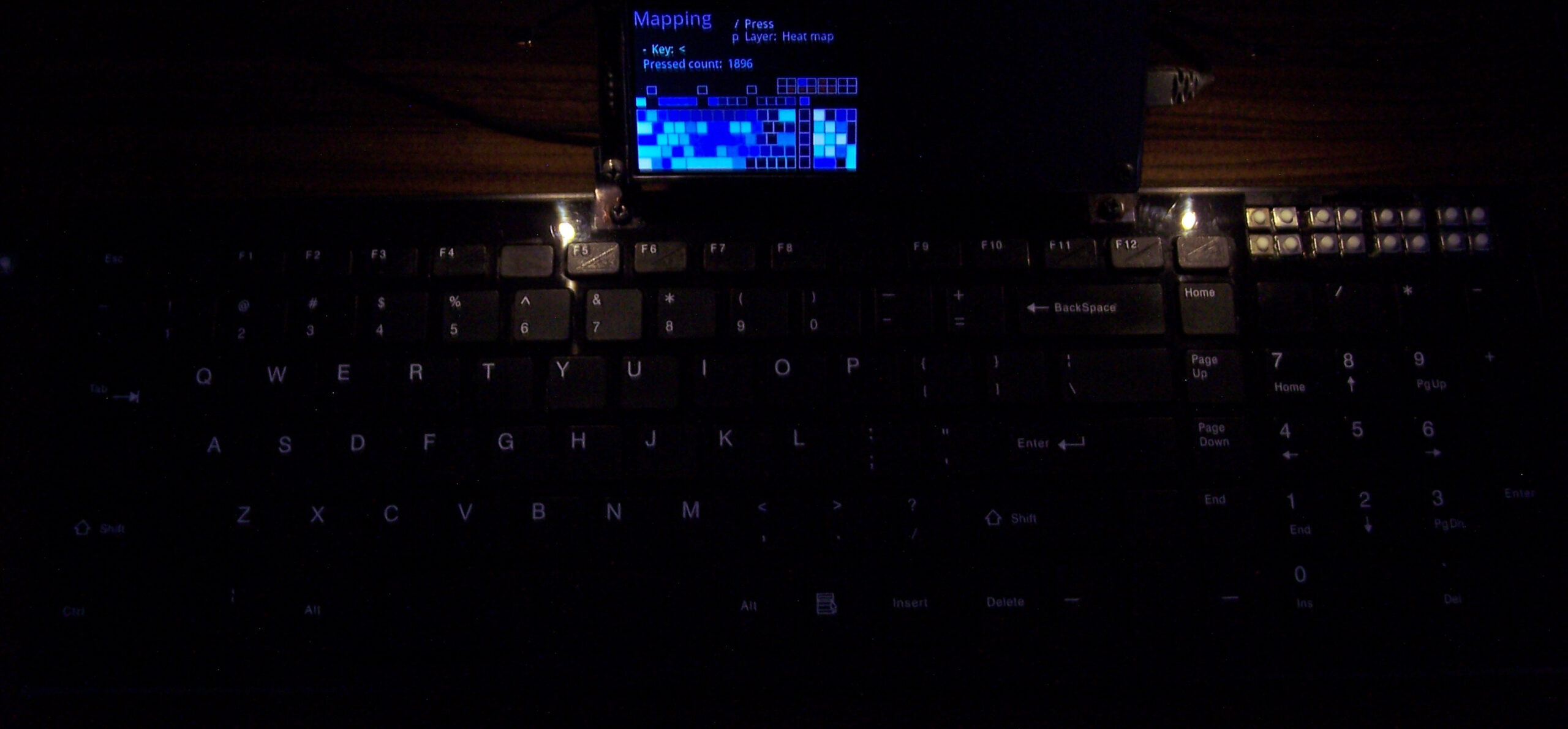
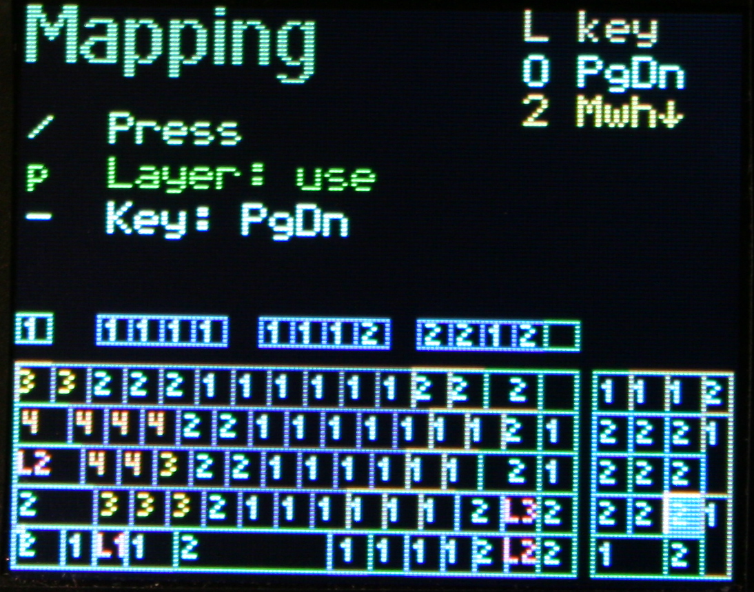
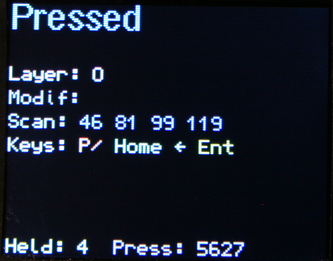
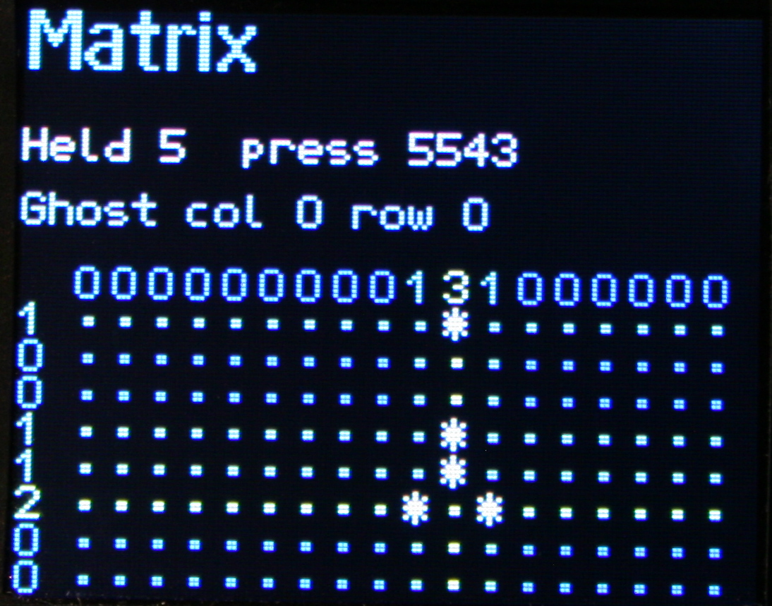
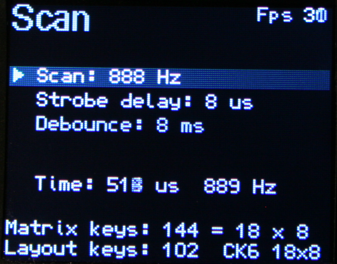
🎛️Testing and Setup pages
Useful when developing and to check if everything is working properly. Scan setup is advanced and adjust which strobe delay, scan frequency, debounce time I need. Matrix page shows the 18×8 keyboard matrix, with my anti-ghosting code working and any issues from too low strobe delay. It now also features X marks on keys that are available in matrix but not present on layout, this makes locating new extra keys very easy.
🔮Demos and Game
Were already present in previous version and even on the first tiny display I used (128×64 mono). Since I have a display, and a powerful MCU, they show their drawing possibilities. They got extended to new resolution with few added extras. Best shown on videos, links below.
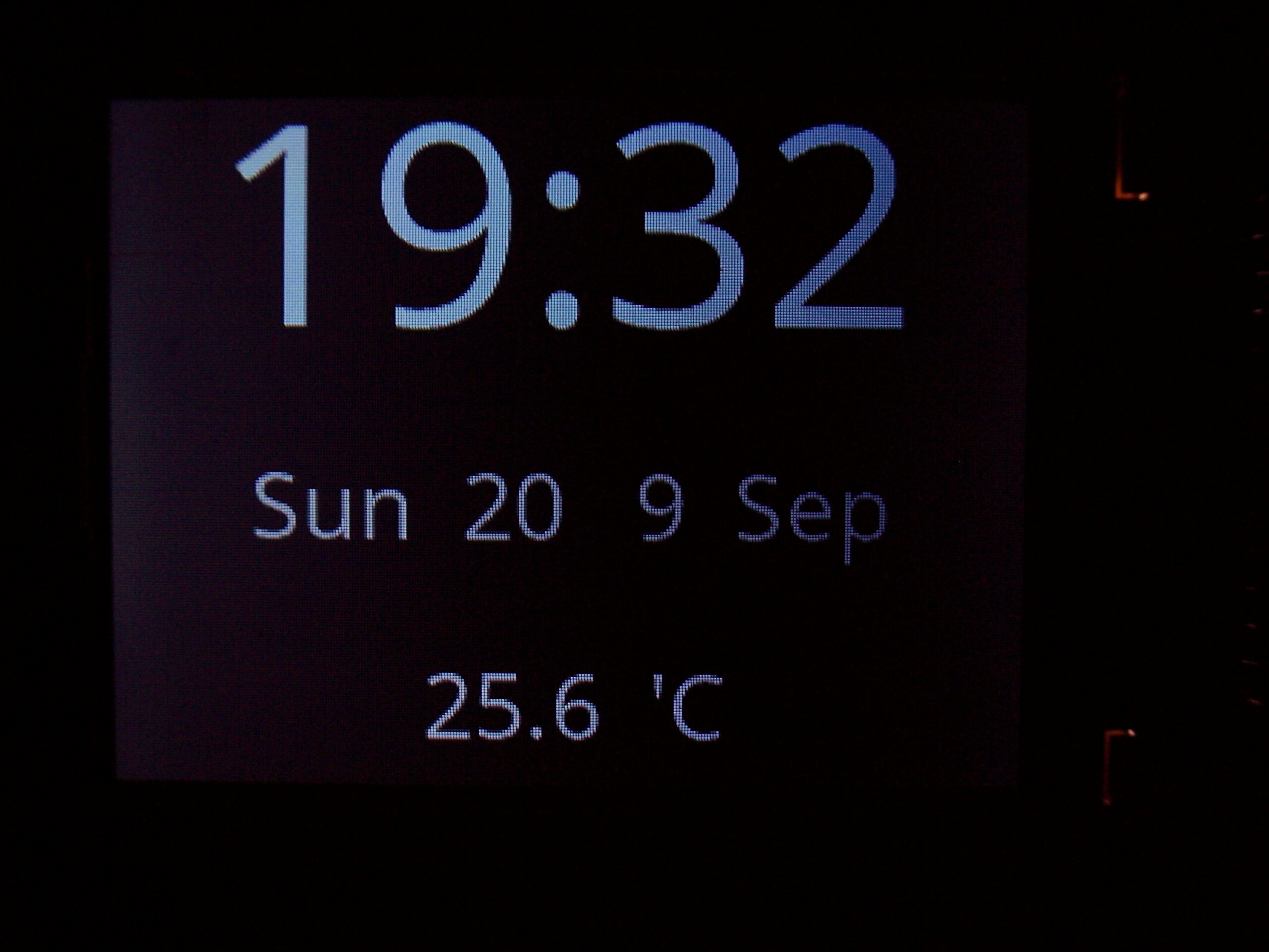
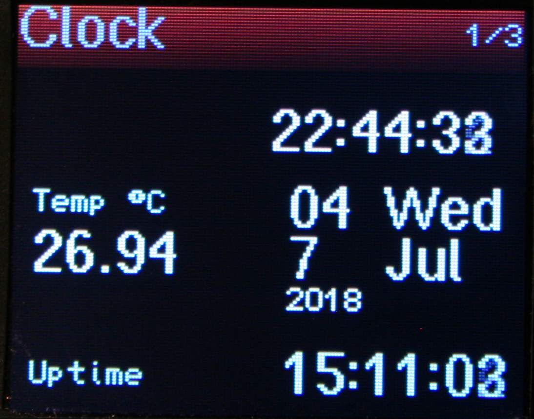
🕙Clock
With date (uses internal RTC, needs 3V battery). Also showing Temperature, read from attached DS18B20 1-wire sensor (optional).
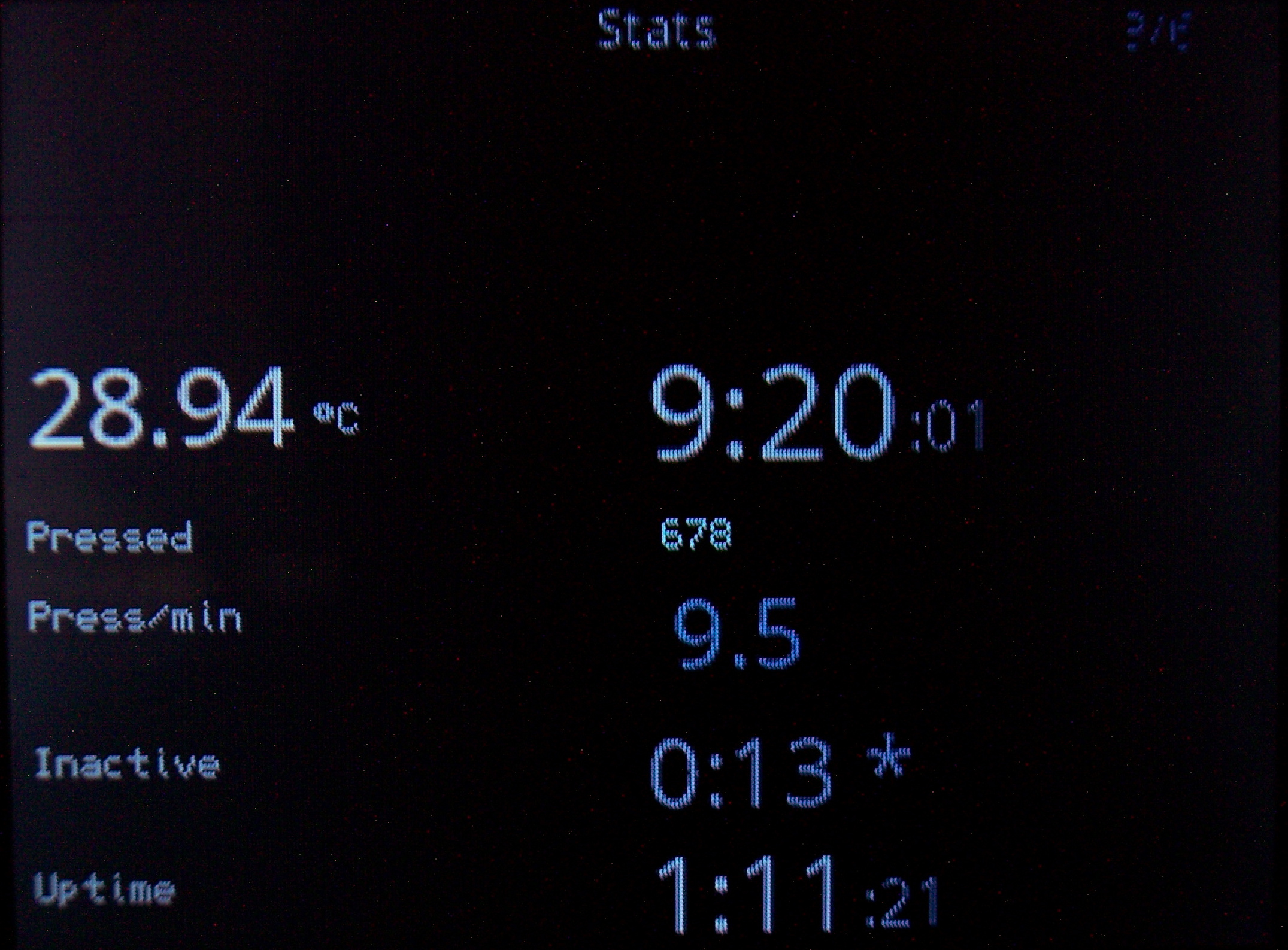
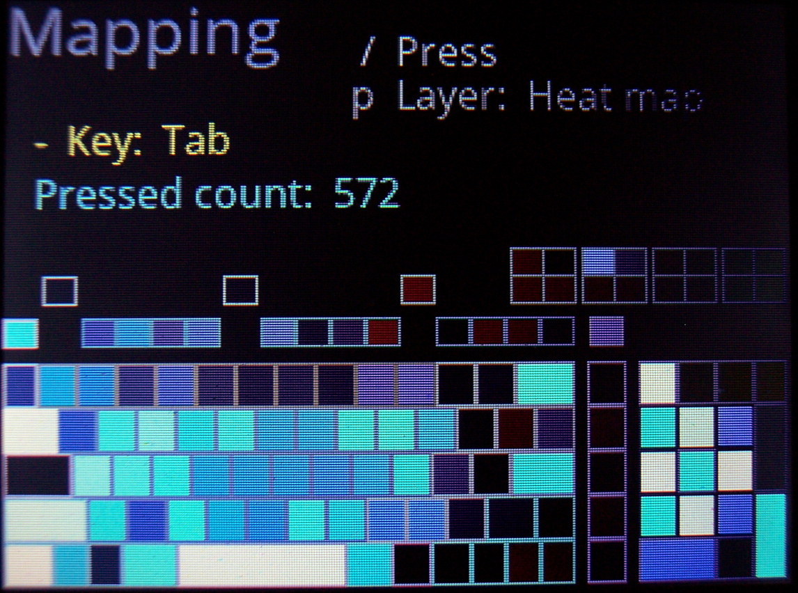
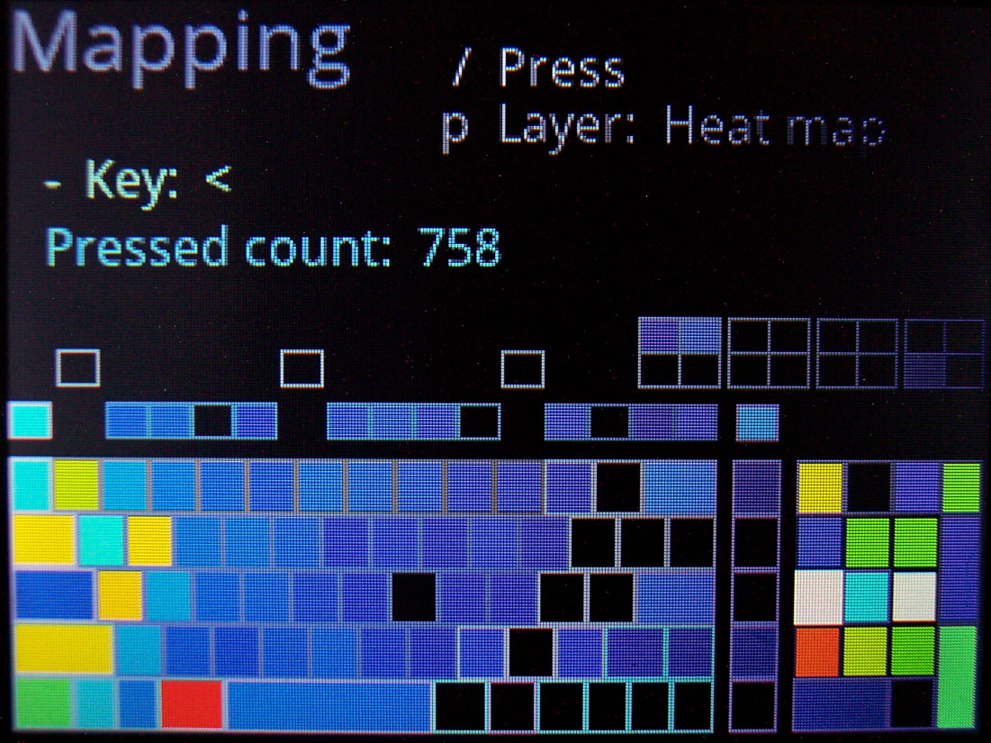
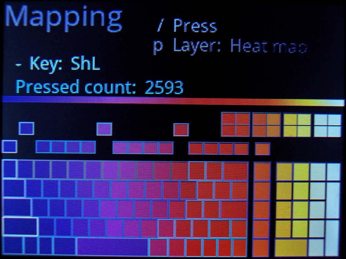
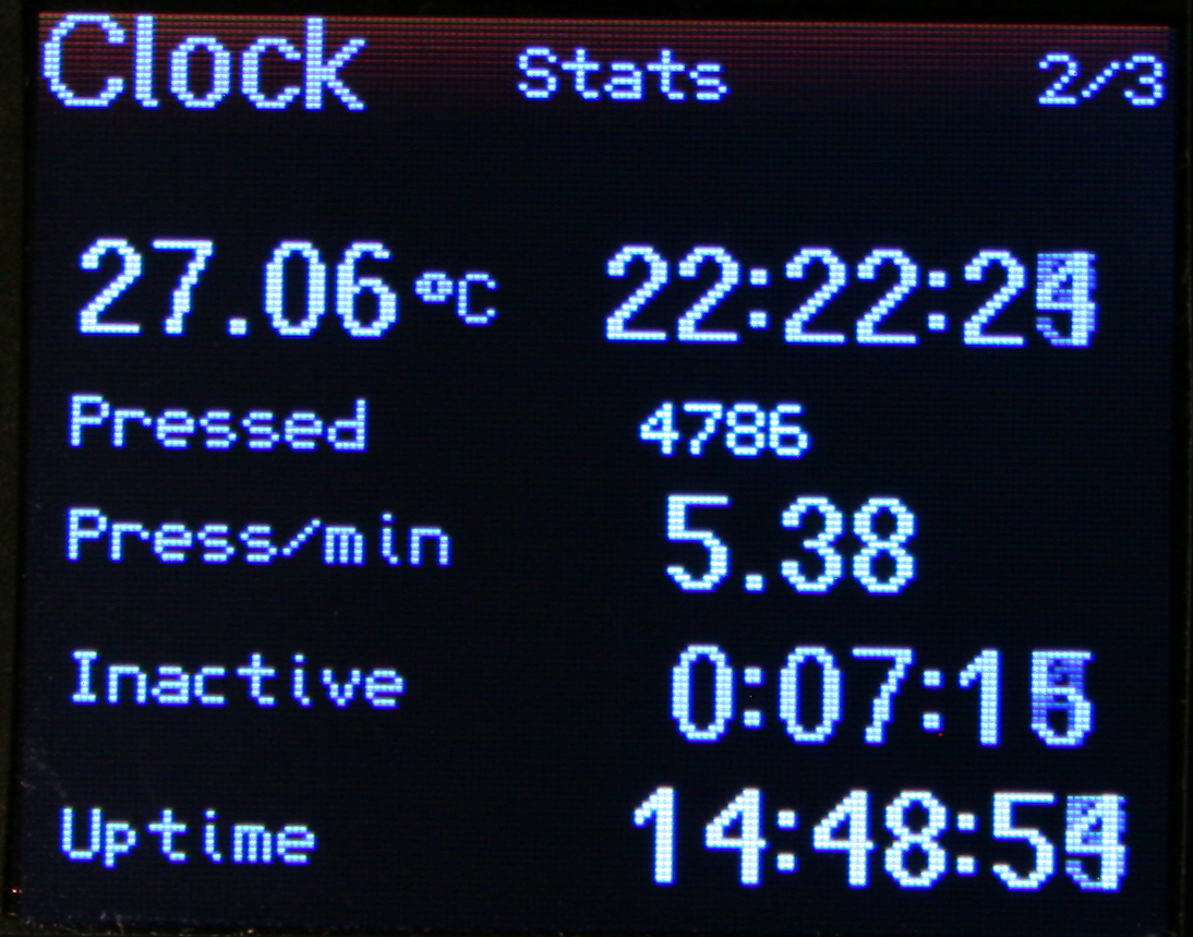
📊Statistics
Clock also displays (on its extended pages) keyboard use statistics:
⌛Uptime. Time since power on or plugged in USB.
🌌Late hour background. Will start slowly showing top of display orange at 22:00 and every 0:30 min going more visible, being yellow after 0:00 (midnight). This is to notify and motivate me to go to sleep when I sit too long at night.
⏱️Active time. I.e. how long I use keyboard without a break (at least 5 min, can be adjusted). Changes color from value. This is helpful to know if I’m doing something too long on PC. After all, it is recommended to take 5 min breaks every hour, it is healthy for spine and hands.
❌Inactive time. The opposite. Useful to know how long was I away from PC (keyboard). Also changes color when over 1 hour. Meaning I probably should have turned it off, to save power.
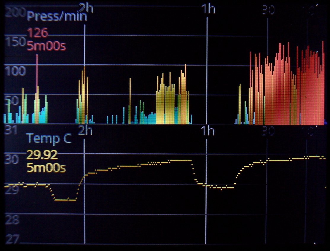
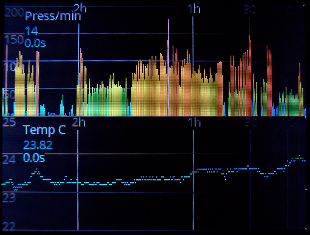
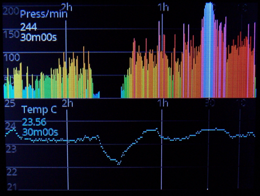
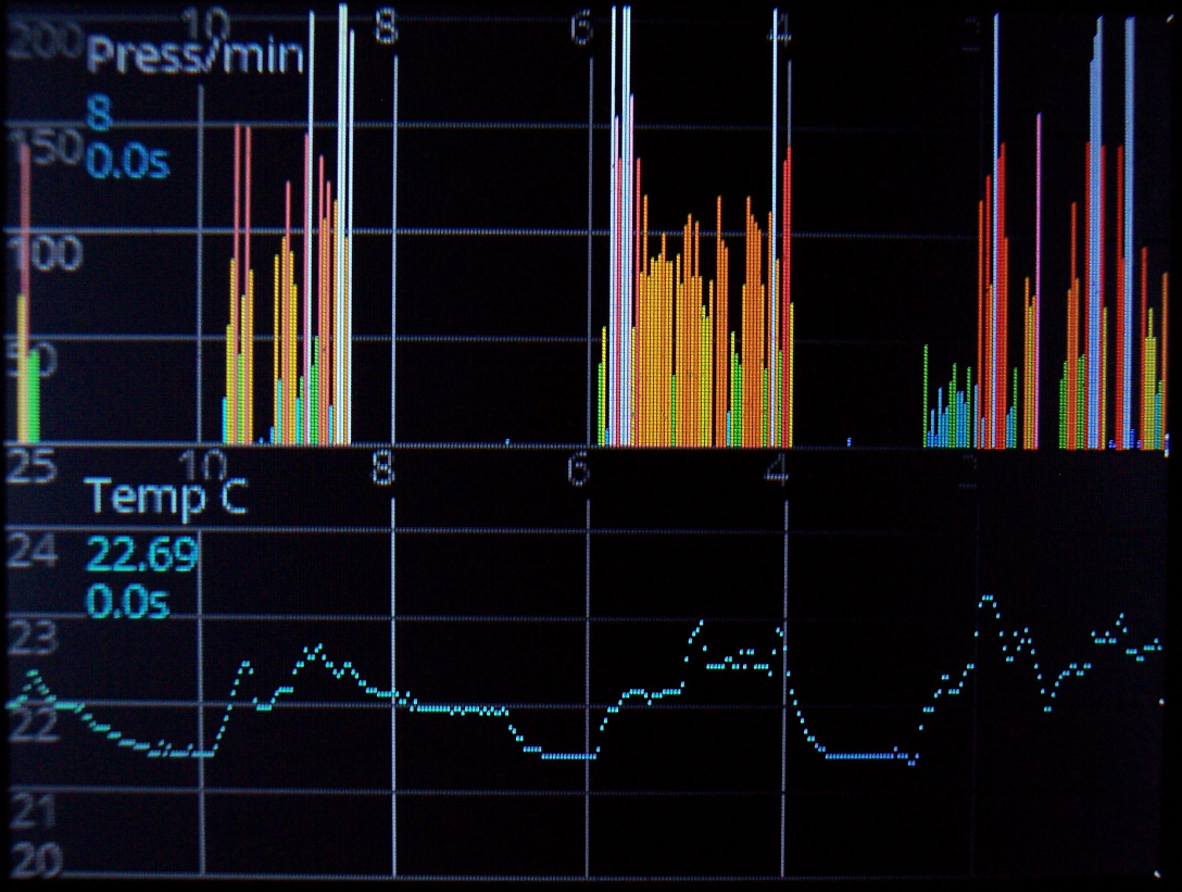
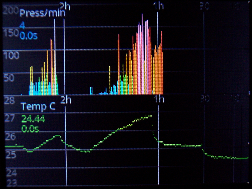
👇Press/min. Typing frequency, so how much key presses are done every minute. A colored value on left, going e.g. red at 120, yellow starting at 50. Also a second value below with total average since power on, with slowly changed value. So it is useful and directly corresponds to how tired will hands be. It’d be great to keep this value below 50, but sadly writing any text (e.g. chat, email etc.) or playing a game makes it go even above 150.
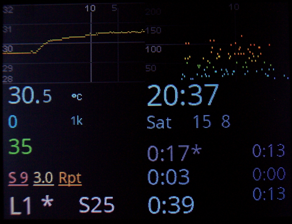
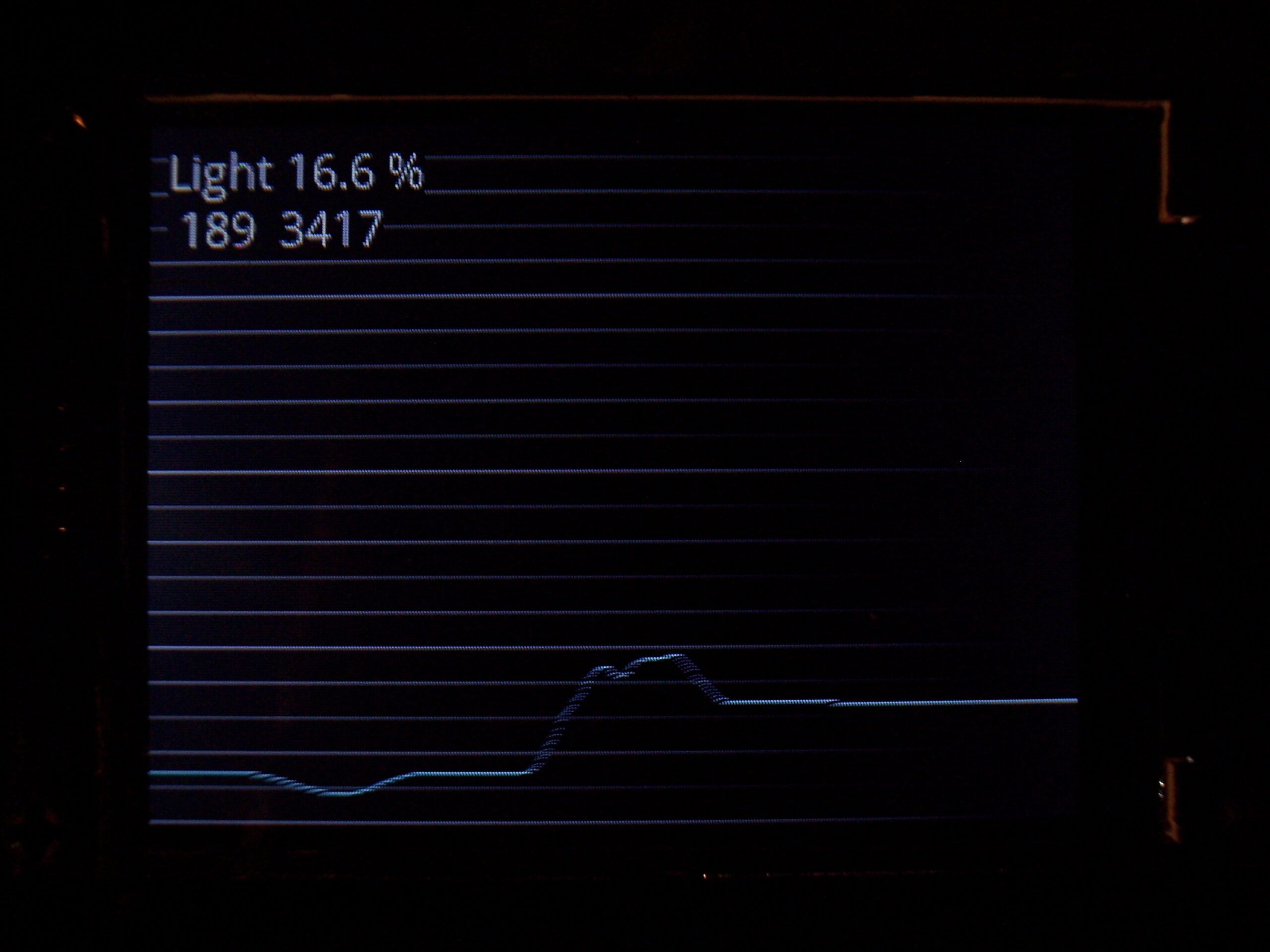
📈Graphs
As a part of clock, they show history of using keyboard (key presses/minute in the past hours). Second one is for temperature history. There are 320 points on display width and parameters for how often a value is added to graph.
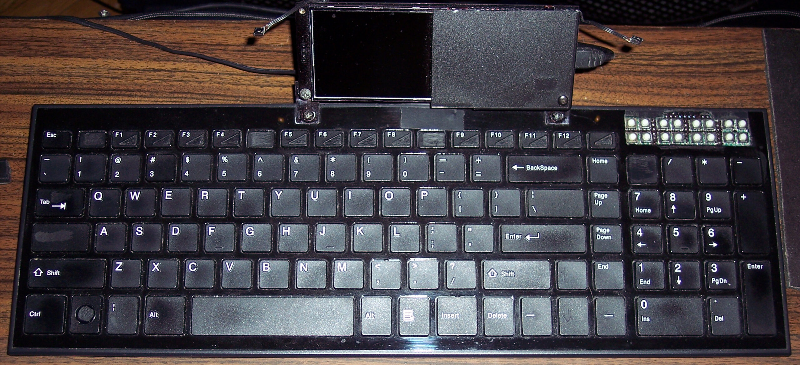
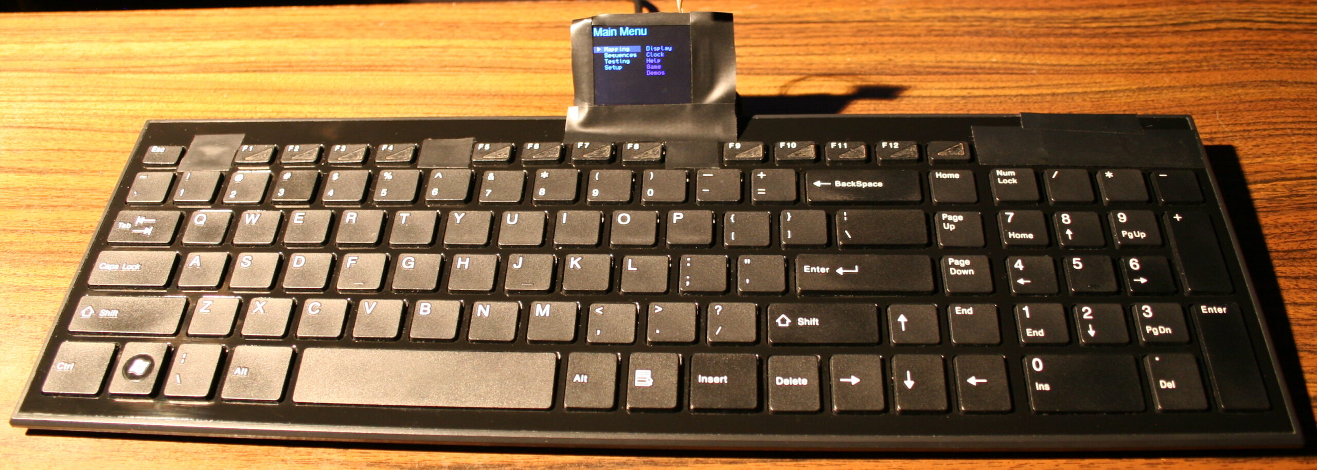
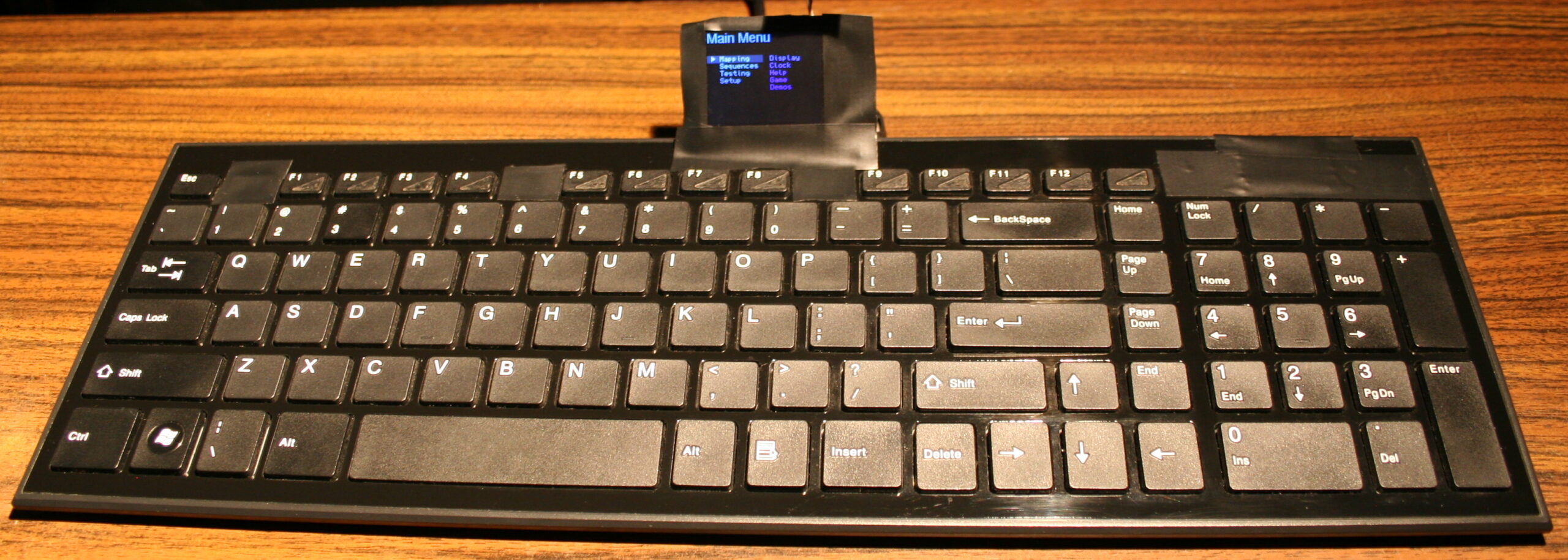
⌨️Keyboard CK9
I upgraded my 2018 keyboard CK6 with this bigger display and K.C.4 and it became CK9. I also added tiny extra keys, lots of them. Above Numpad, 2 rows of 8 or in other words 4 groups of 4. Surely will come handy for e.g. internal functions or could be extra F13-F24 keys for OS. The keyboard has visible tear on few keys already, well I use it since 2016 (was CK3 first). Nothing yet, compared to the 14 year old one (CK7/4/2).
✍️Motivation
My previous version of KC and keyboards with it were quite useful and the 1.8″ color display was good too. The keyboard drawn on screen was minimal. Keys with one letter/digit/symbol had a 5×7 font, but 2 letters needed a tiny 3×5 font. It worked, but didn’t look great. So the new display is bigger 2.8″ and has about 2x resolution (320×240 vs 160×128).
The main reason for this upgrade though was the new Teensy 4.0 with a MCU that runs at 600MHz. It seems to be the fastest one available (on a board with USB, ready to use). And is even way faster than all previous. I already didn’t like Arduino in 2014 when I got interested in MCUs (again), seemed like a stone age relic compared to Teensy 3, but today I can say they probably have computational power of a rock, when compared.
The result is constant 45 frames per second almost always. This is what 600MHz MCU with SPI set at 60MHz for this display does, while using DMA for transfers and double buffered drawing (one buffer is being sent by DMA to display, while MCU draws new frame in second buffer, at the same time).
⚖️Comparisons
Of course, there were many projects of using a big display with slow MCU even. A MCU not having enough RAM for screen buffer. But this means very low refresh rate (low Fps) and flickering (blinking when redrawn).
There are few open source keyboard controllers, I think none of them even have a display, and some still use ATmega 8bit MCUs. Their requirements for program and RAM (memories of a MCU) are minimal, way lower than mine. And the price will be lower too. But the main flaw coming from it, is having to compile on PC and upload to MCU after any change. This is a big nope for me.
📢Rants
So for me, this is now the present (not the future anymore). And well honestly, whenever I see a custom keyboard picture I’m just asking: “where’s the display?”. In addition, seeing Cherry MX or any switches turns me away immediately.
Because there is one more very important thing that is the light press modification. All my keyboards since 2005 have it and it’s just the default for me. Sadly all commercial keyboards are garbage in this matter and people continue to produce keyboards that have a tactile feel, 4mm travel and around 50 gram force to press. Well for me this is the middle ages era. This can cause injuries (Carpal Tunnel Syndrome). And I guess it feels awful for those having pain from using such keyboards.
For my modding process (of reducing rubber dome keys press force and travel) pictures are in this gallery and I made a video of it recently (it is CK5).
✅Summary table
For reference, here is a table with current status of all my keyboards, since start until present day:
Name
Assembly year
Original keyboard
Keys actuation
[gram force]
Notes
CK3 > CK6 > CK9
2016 > 2018 > 2020
A4 Tech KX-100
23 g
Cheaper, bit wobbly, but more keys
CK2 > CK4 > CK7
2005 > 2016 > 2018
Logitech Ultra X Flat
33 g
Stiff foil, old, extra keys
CK5, CK5b
2015, 2020
A4 Tech KV-300H
9-18 g
The lightest foil
CK1
2004
Logitech Ultra X Flat
25 g
First, old, had extra keys,
now only for testing, 1 row dead 💀
This is my own keyboard controller software used in my keyboards CK6 and CK7 (upgraded CK3 and CK4), running on Teensy 3.2 (or 3.1) with a color LCD display (160×128, ST7735 chip). It allows editing all: key mappings, layers, sequences/macros in real time on its display. It is continued in newer version with Teensy 4 and bigger display.
📂Sources
My firmware sources are here. I called it K.C. (aka “Kacey”) simply from Keyboard Controller. A catchy cool name for software is a thing, isn’t it.
The readme with all key features is visible there too. Here will be a more practical description.
✍️Motivation
My previous keyboards CK3 and CK4 were quite useful. But there were few flaws that I wanted to improve. They had a very tiny display, sure it did the job, but wasn’t convenient to look at for longer. Since I based my code on existing kiibohd controller software, there were few problems. Any change in key bindings had to be done on PC, needed to build binary and upload it to MCU. That’s a long way to e.g. check if it’d be better if I swapped some keys. Not to mention doing it at work. Lastly, there were few bugs which I couldn’t spend more time trying to fix.
So, it’d be better indeed to start writing my own code. And that’s what I did. Right now I can’t find a reason not to use my controller code. Sure, it was easier back then to get started, knowing there is an open source keyboard controller and it runs on Teensy 3.1, this is how I got into it. My code surely doesn’t have stuff present in kiibohd like NKRO support, keyboard LEDs animations and other fancy things I will likely never need. But it now does have features I wanted and it wasn’t that difficult to code them.
📊Features
So the code features are:
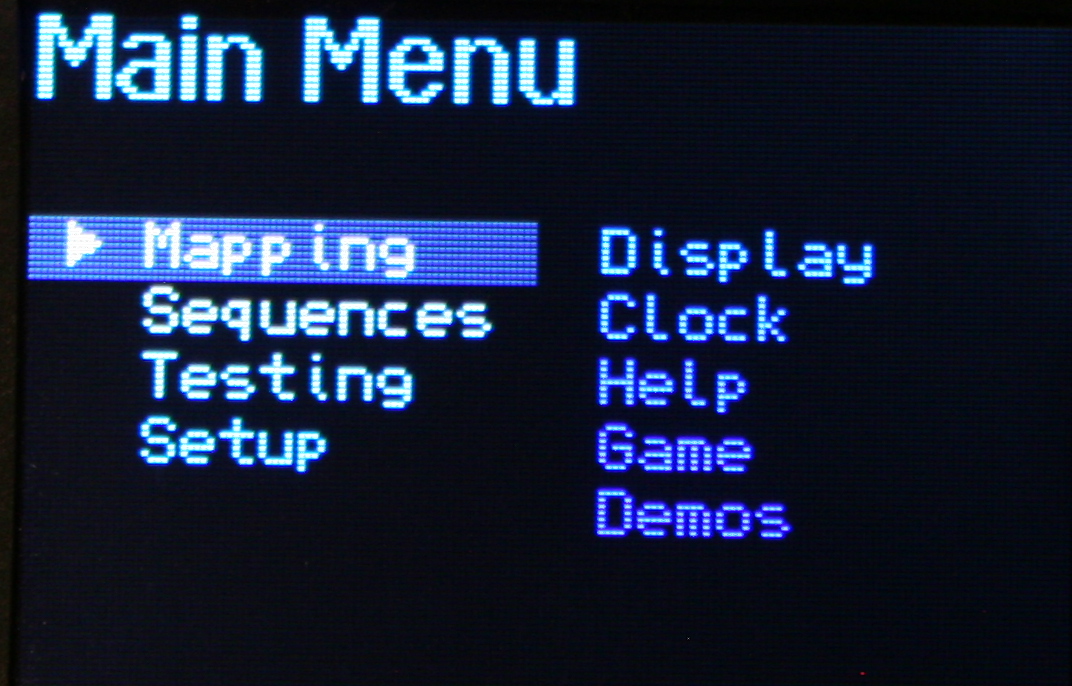
🪟Display with menu, where you can edit everything possible (that I needed so far).
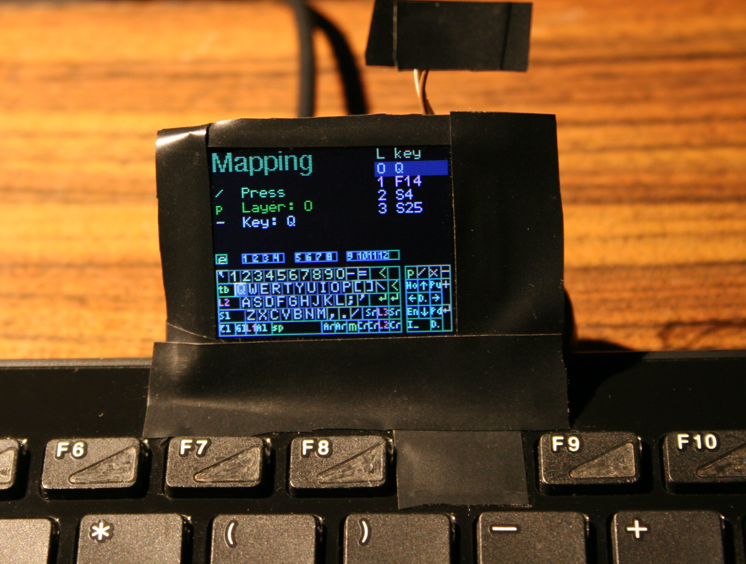
🔠Key bindings (mappings), i.e. what USB codes will the physical key send to PC when pressed. There is a pick list with all common keys (and internal functions) to choose from when binding. It has group colors and group filter for easier orientation.
⌨️Keyboard layout drawn on display. Shown when editing mappings. Has a cursor to move around between keys, can also jump to key by pressing it.
🧮Layers. If you hold a key, whole keyboard layout changes giving you other keys. Kind of like the Fn keys on laptop but much more useful and customizable. Surely a common feature in custom controllers (like tmk or kiibohd).
🔤Sequences aka Macros. Basically any key combinations (for key shortcuts) and any sequences of key presses (for e.g. passwords). Not typing passwords myself, when my keyboard could do it, was my first reason when starting with keyboard controllers back then. Sadly even in kiibohd you couldn’t change them without rebuild and upload. This then was possible in my fork of kiibohd. To be convenient, I am showing (short) sequence preview where possible. So when editing Mapping (for a sequence key), when picking a key from list or Testing pressed keys (if a key runs a sequence). I am also showing in sequences view any mapped keys that run selected sequence.
✅Sequence commands are an even further extension. If you have an editor on display (basically a simpler editbox) one could put special commands (beside sequence keys), that e.g. wait for few seconds, or change how slow the sequence will run (useful for putty). Newest ones allow putting comments, useful if you have lots of sequences and want to rather see what it’s for, not what it will press. And hiding sequence from preview, useful if you don’t want to show important passwords on GUI.
🖱️Mouse keys, i.e. keys that will move mouse, press mouse buttons or scroll mouse wheel. Also featuring acceleration and even parameters for it and speed in GUI.
I now even have mouse commands with all mouse actions possible to add in sequences. Some stupid programs don’t allow everything using keyboard and specifically want you to click with mouse. But hey, now even this could be done automagically by my keyboard.
🎛️Testing and Setup pages. Those are quite useful when developing and in normal use to check if everything is working properly as intended. Scan setup is nice e.g. to check which strobe delay, scan frequency, debounce time I need. Matrix page shows the 18×8 keyboard matrix, with my anti-ghosting code working and any issues from too low strobe delay.
🔮Demos and Game. Were already present in my fork of kiibohd. Now extended with new presets to color display. Best shown on videos, links below.
🕙Clock with date (internal RTC, needs 3V battery) optionally also showing Temperature, read from attached DS18B20 1-wire sensor.
⚙️Internal functions, e.g. to dim brightness or toggle GUI, by keys on other layer.
⌨️Keyboards CK6 and CK7
I then upgraded my 2016 keyboards CK3 and CK4 with bigger, color display (160×128 LCD, ST7735) and K.C. They now became CK6 and CK7. Apart from the new displays and my software, the keyboards are the same.
The CK7 is the oldest one, comes from CK4, which in fact was done from CK2 (2006) and is now 12 years old… Still doing fine. Well this proves then, that cutting and gluing rubber domes is nothing that would decrease the lifespan of a keyboard. Even recently folded keyboard foil since CK4 works okay.
▶️Videos
There are a few videos of my keyboard CK7, showing most of K.C. on its display: (no talk and very poor quality).
View – Short video of keyboard and closeup at display.
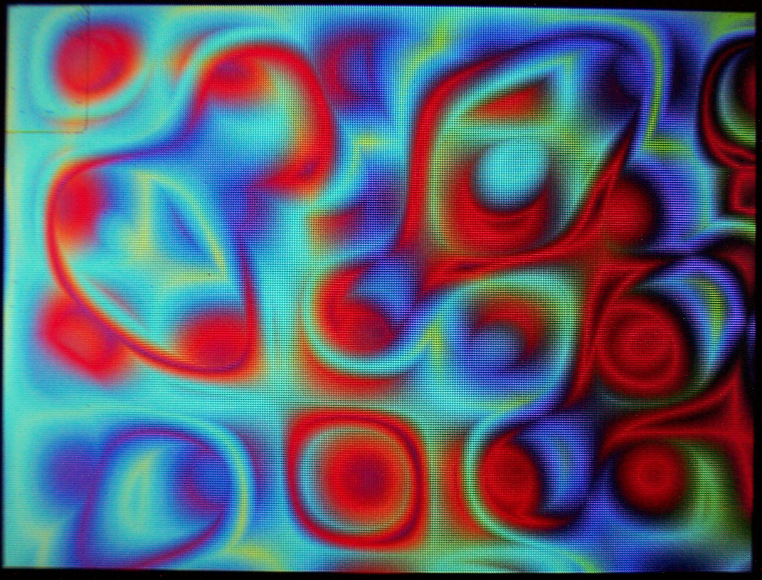
Plasma – Quick and colorful show of presets of plasma fullscreen effect. It runs at 10-30 frames per second. Note that I overclocked Teensy 3.2 here at 120 MHz, HW SPI runs at 30MHz. My other keyboard CK6 has Teensy 3.1 at 144MHz, SPI at 24MHz, it gives about 1.5 Fps more here.
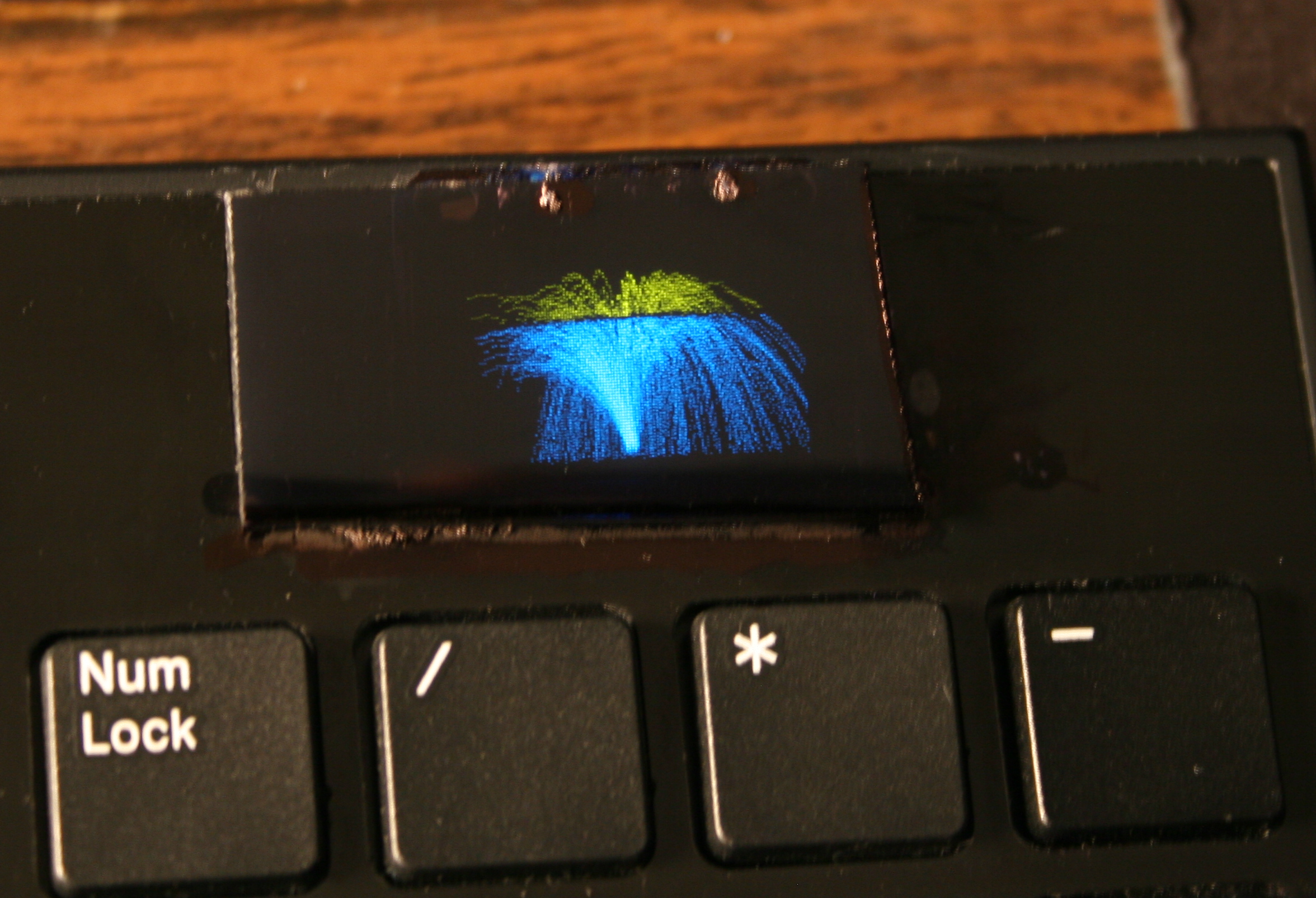
Demos – Showing rest of demos: 3D Polyhedrons with diagonals, Wave, Fire (not real) and the older ones: 2D waving CK Logo, Space, Balls, Fountain, Fonts.
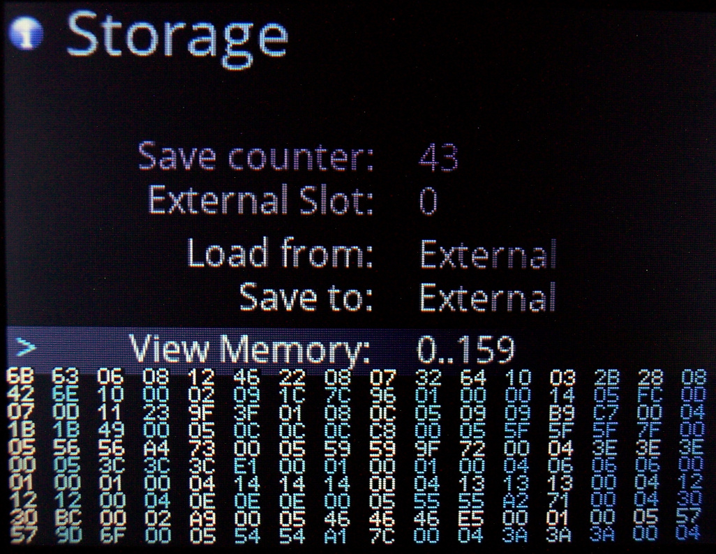
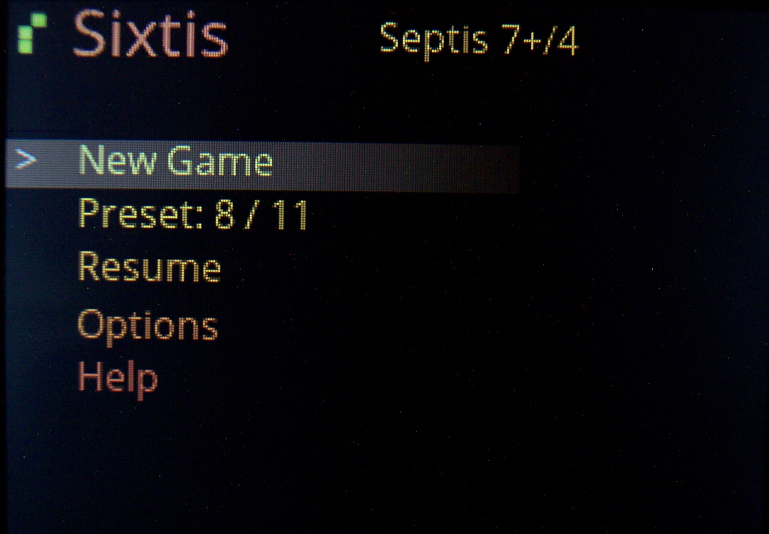
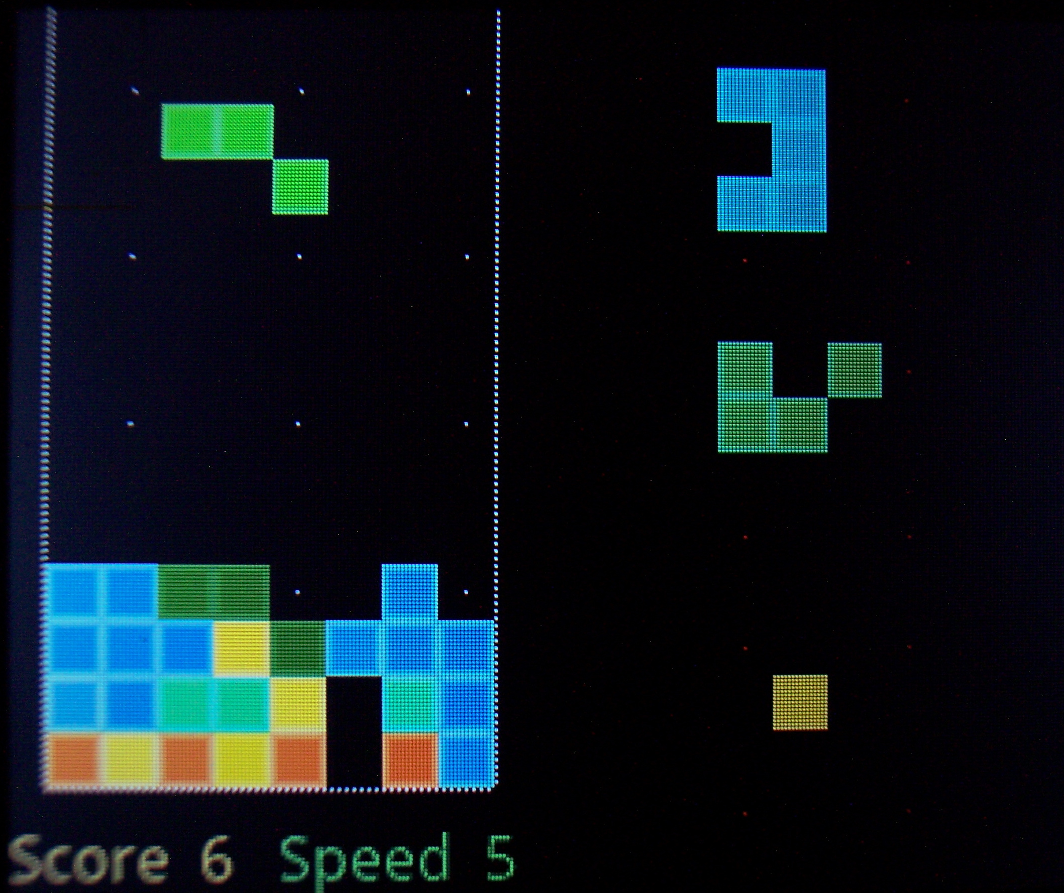
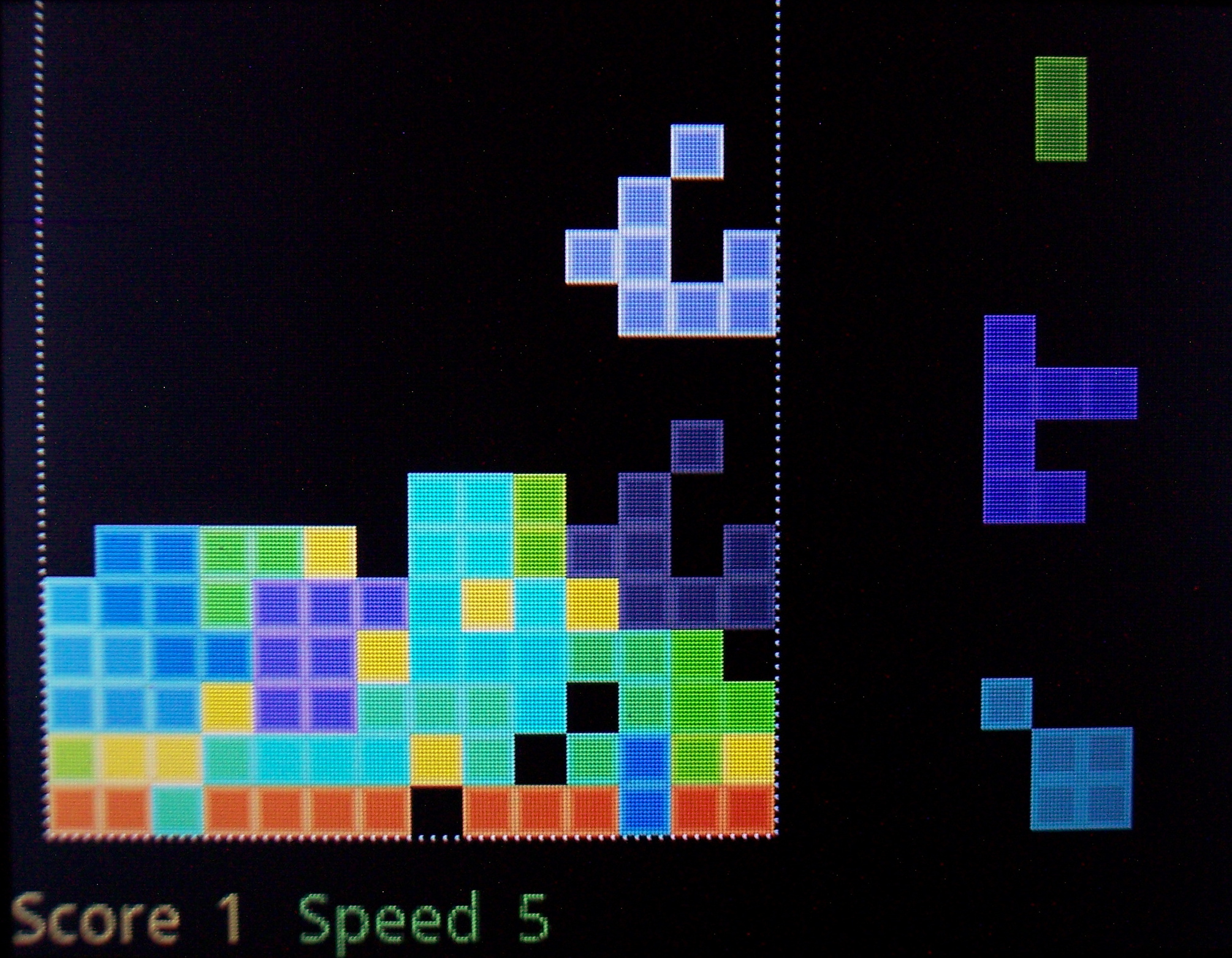
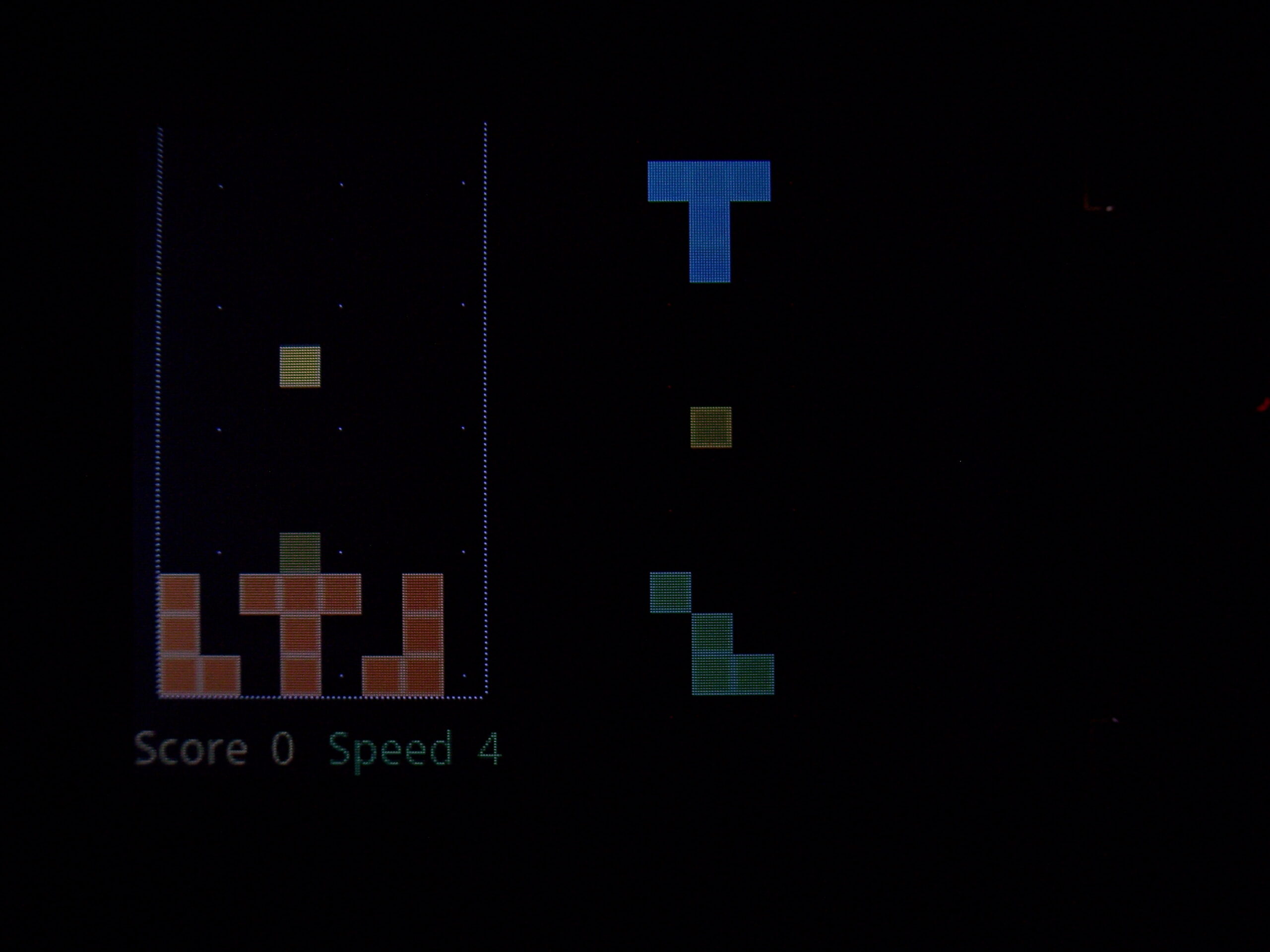
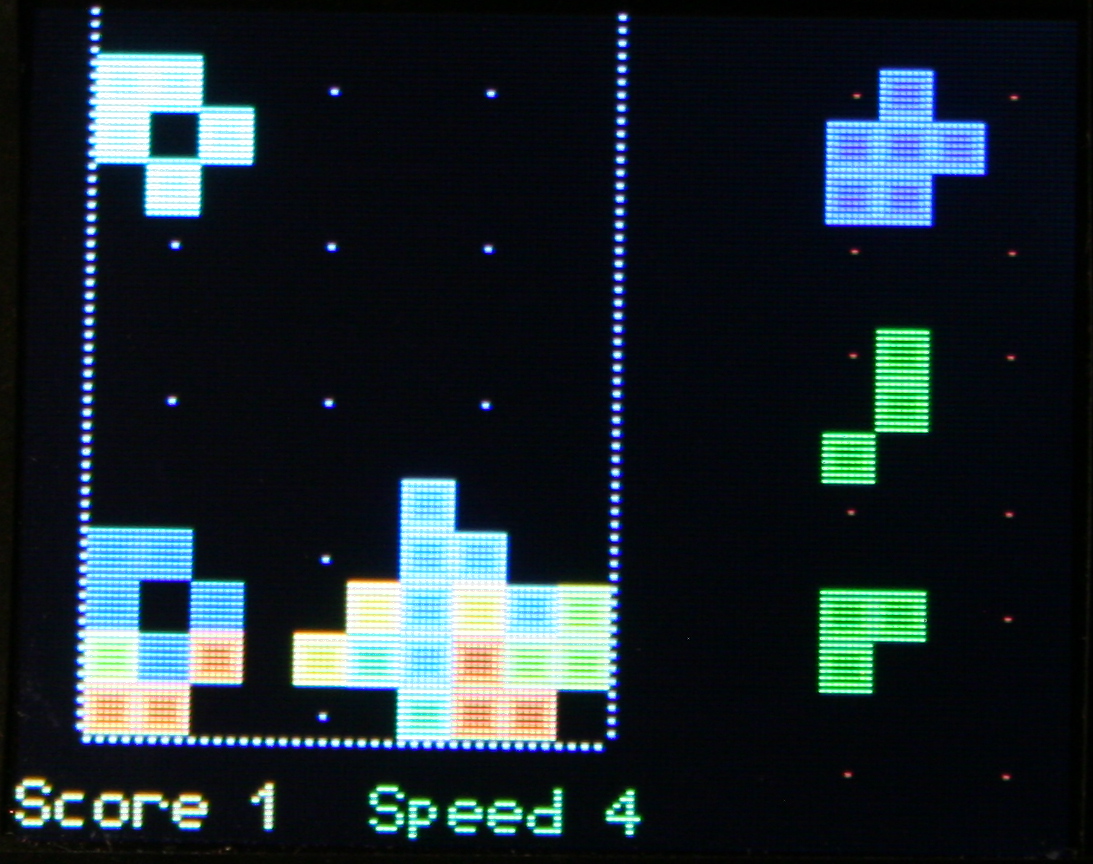
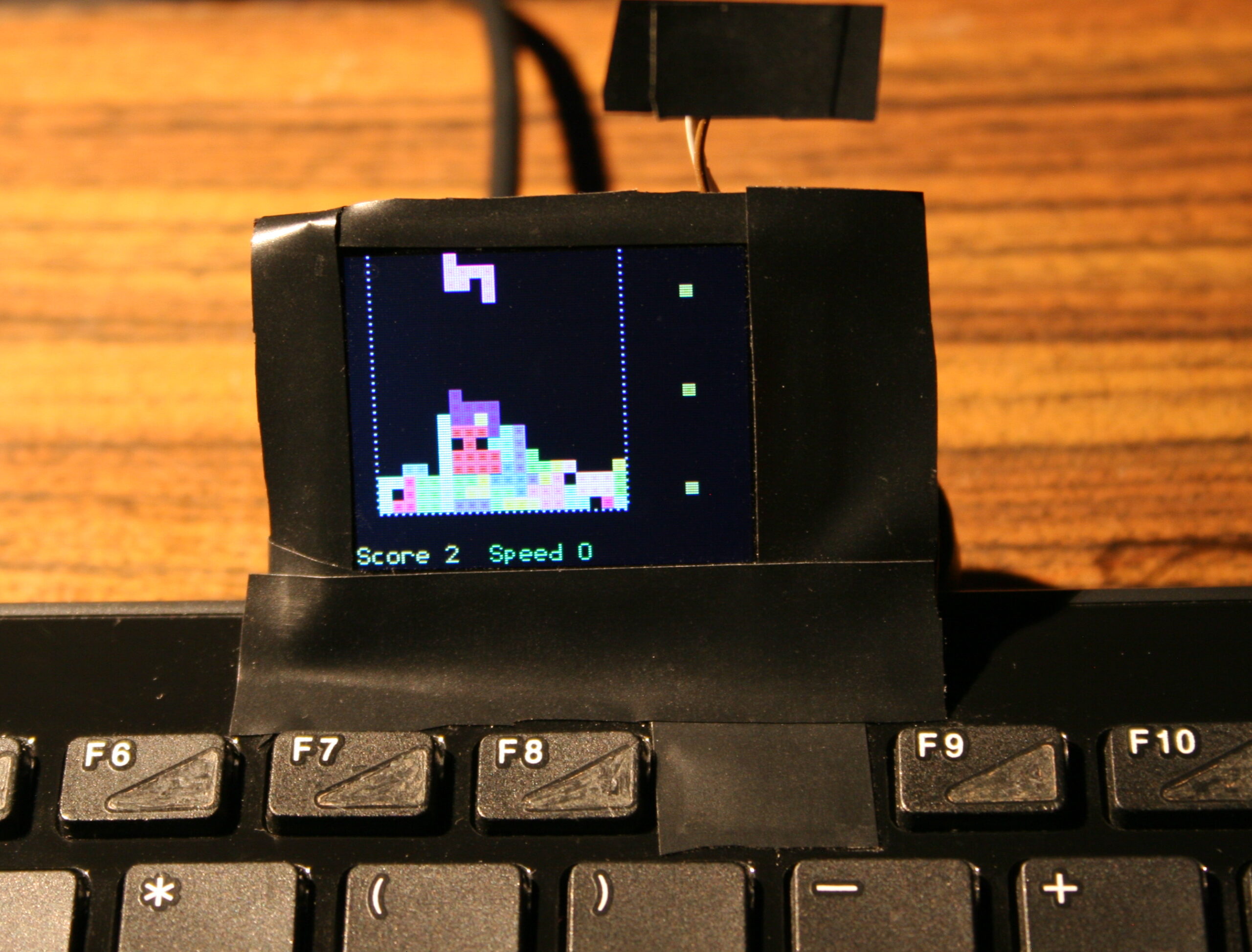
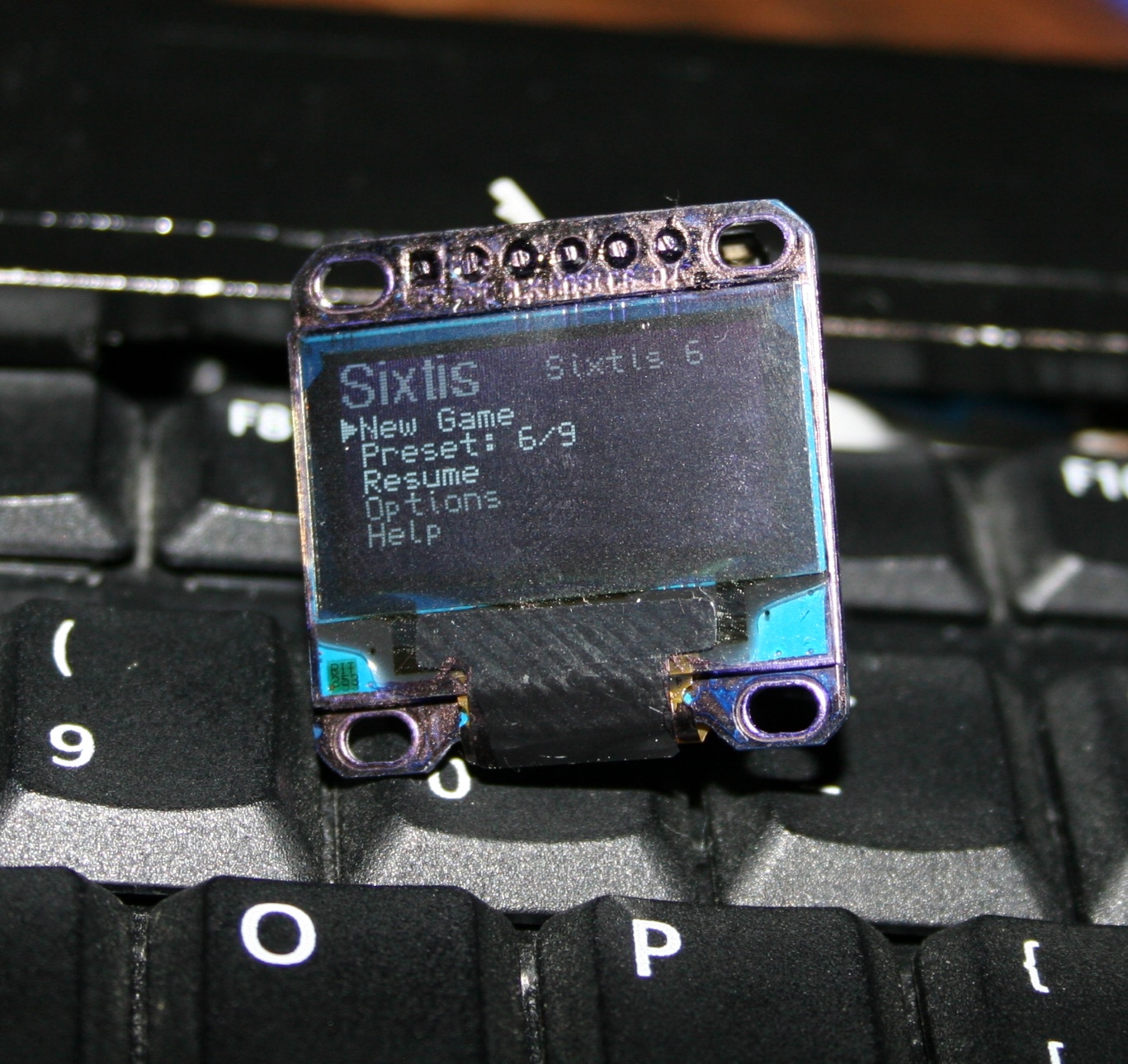
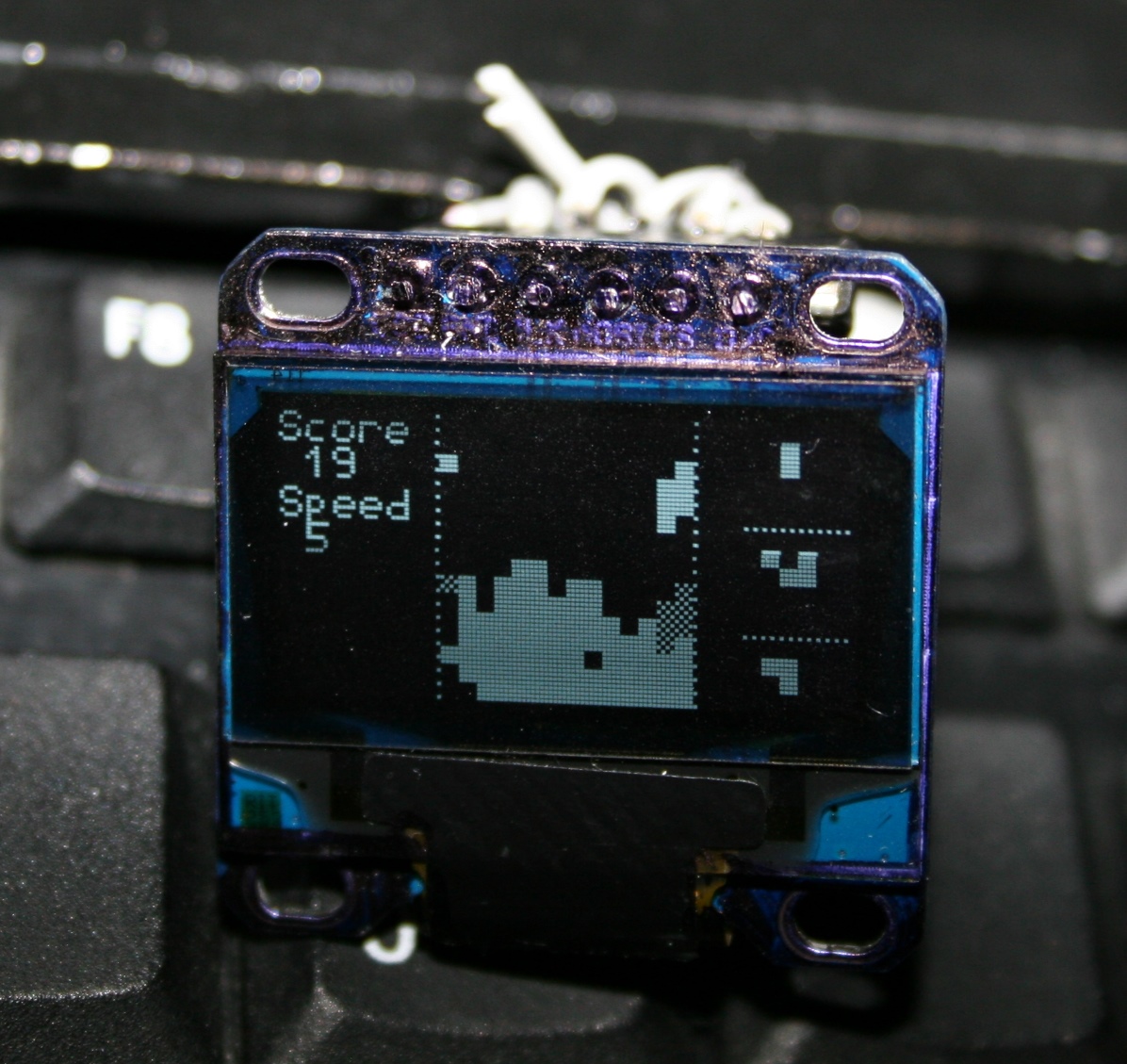
Game – falling blocks (Sixtis), or my version of it. It has 11 game presets, generated blocks, possibly diagonal, with many parameters for custom games.
Features – A detailed look at features, no sound or descriptions though. Editing mappings, sequences, testing etc.
Link to my channel with electronics videos here, mostly from my keyboards.
☑️Summary
For reference, here is a table with current status of all my keyboards, since start until present day:
Name
Assembly year
Original keyboard
Keys actuation
[gram force]
Notes
CK3 > CK6 > CK9
2016 > 2018 > 2020
A4 Tech KX-100
23 g
Cheaper, bit wobbly, but more keys
CK2 > CK4 > CK7
2005 > 2016 > 2018
Logitech Ultra X Flat
33 g
Stiff foil, old, extra keys
CK5, CK5b
2015, 2020
A4 Tech KV-300H
9-18 g
The lightest foil
CK1
2004
Logitech Ultra X Flat
25 g
First, old, had extra keys,
now only for testing, 1 row dead 💀
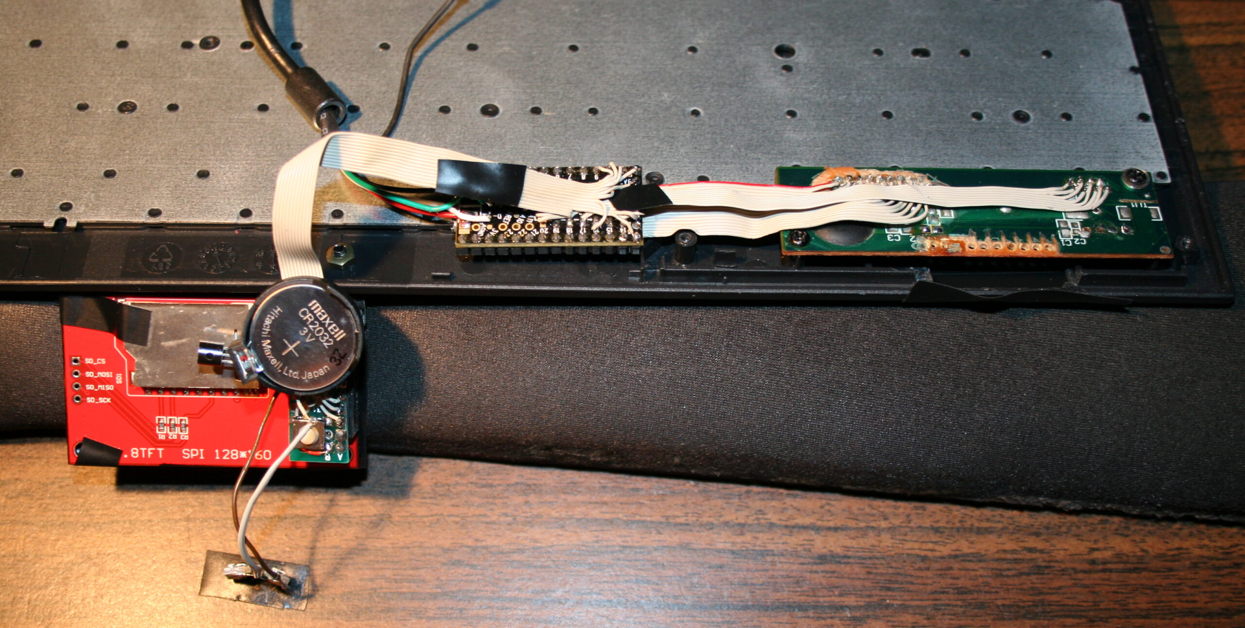
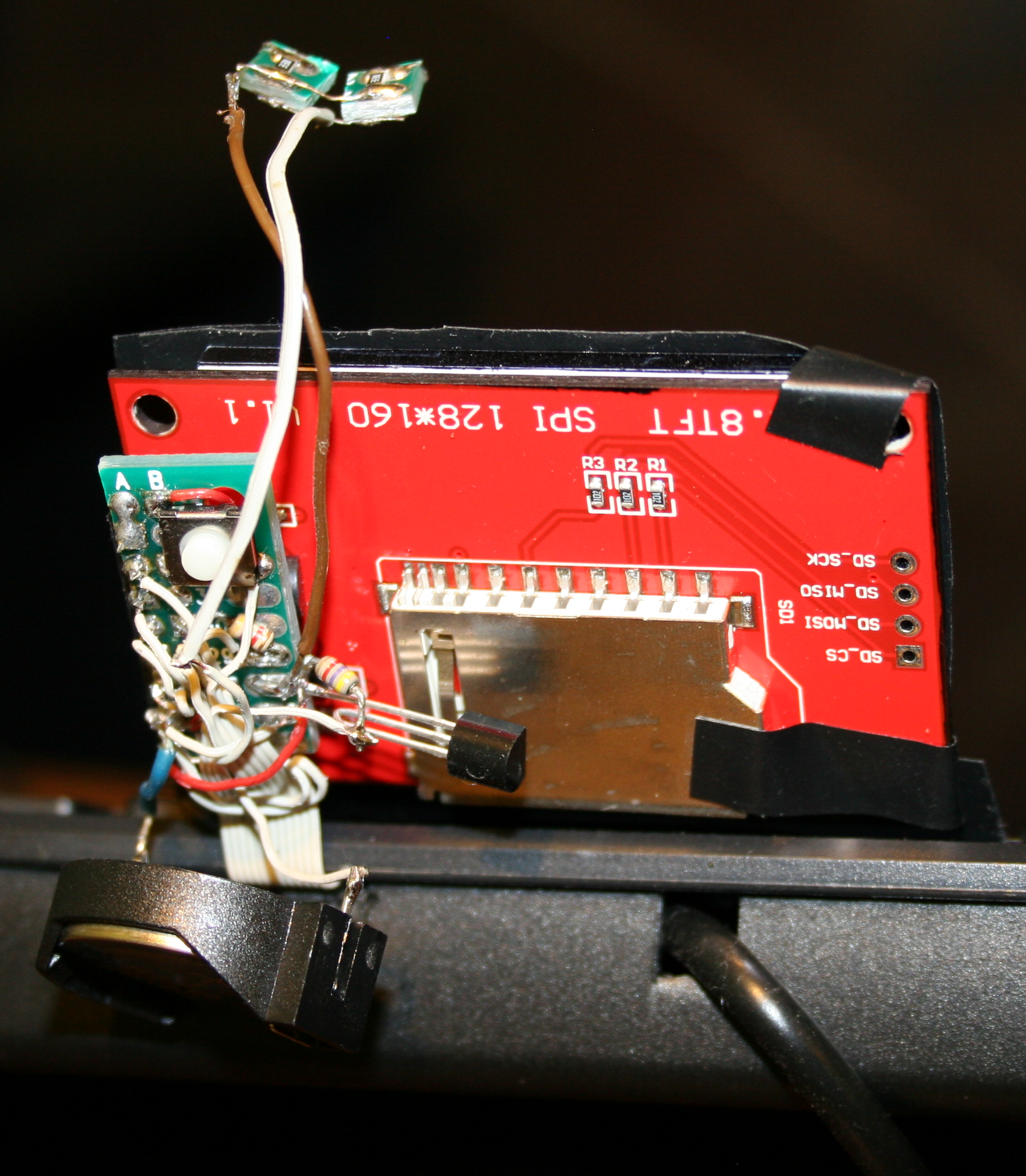
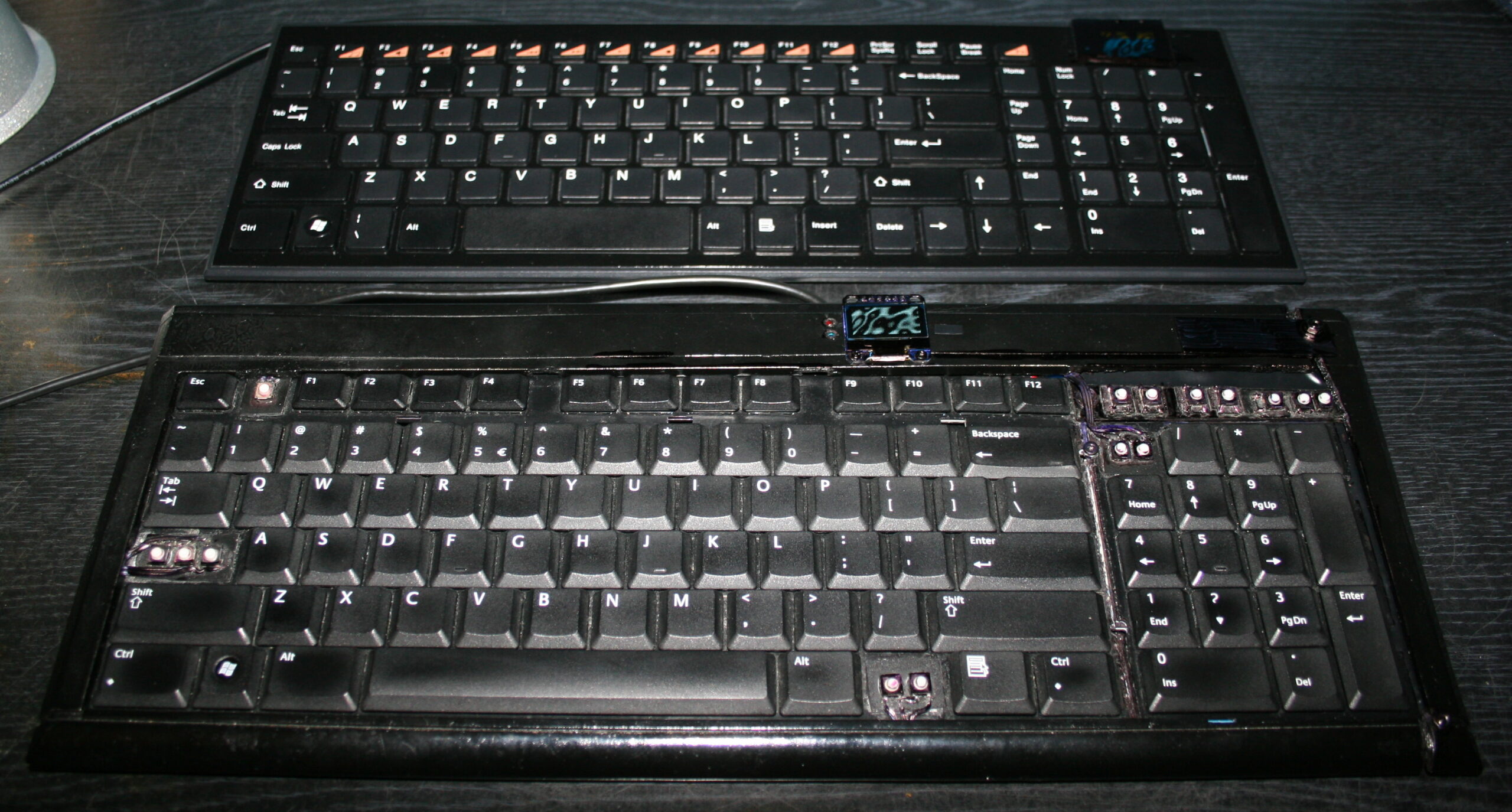
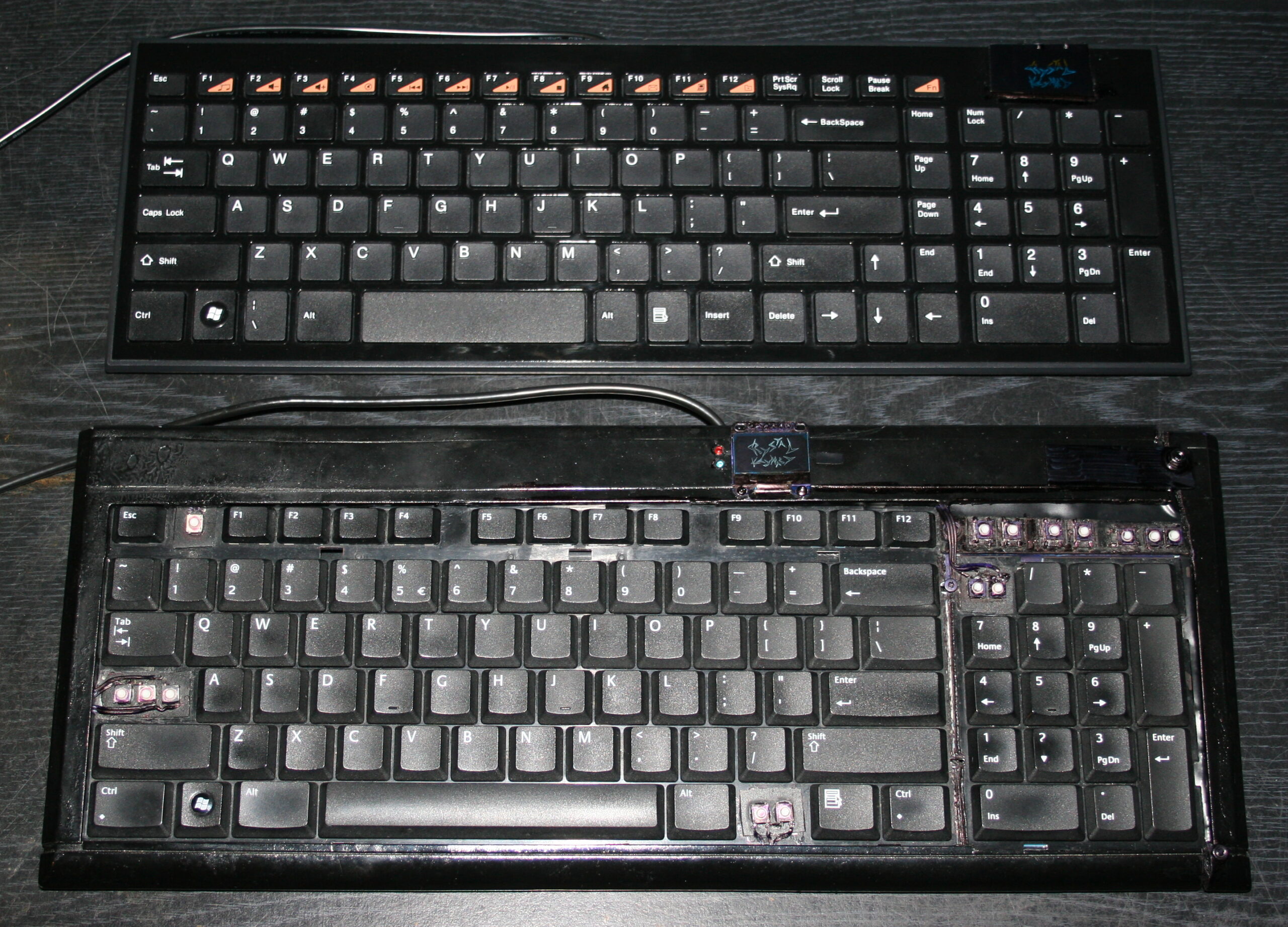
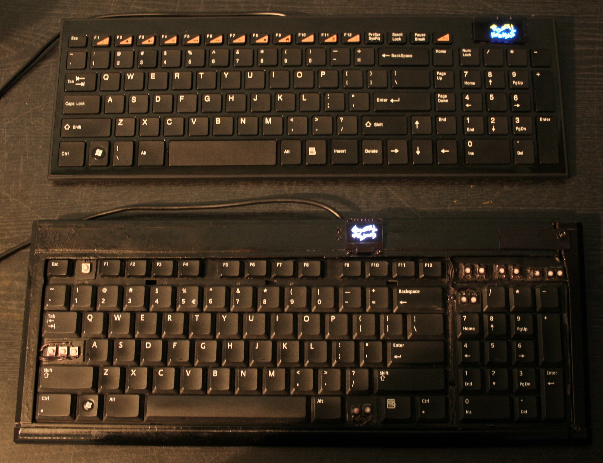
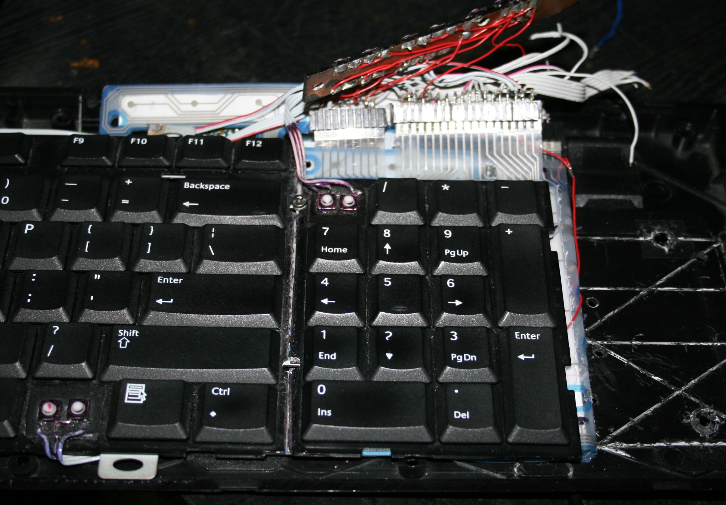
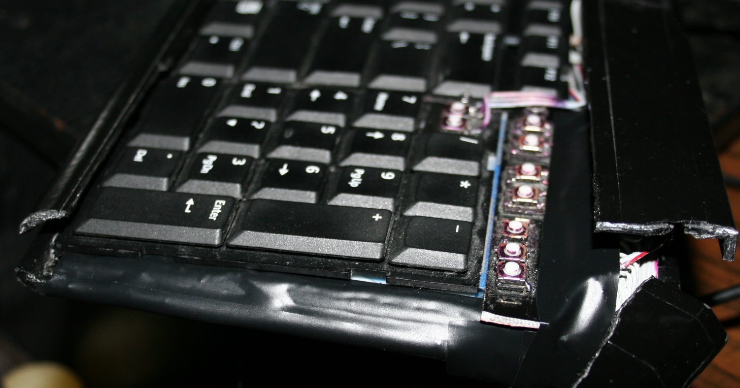
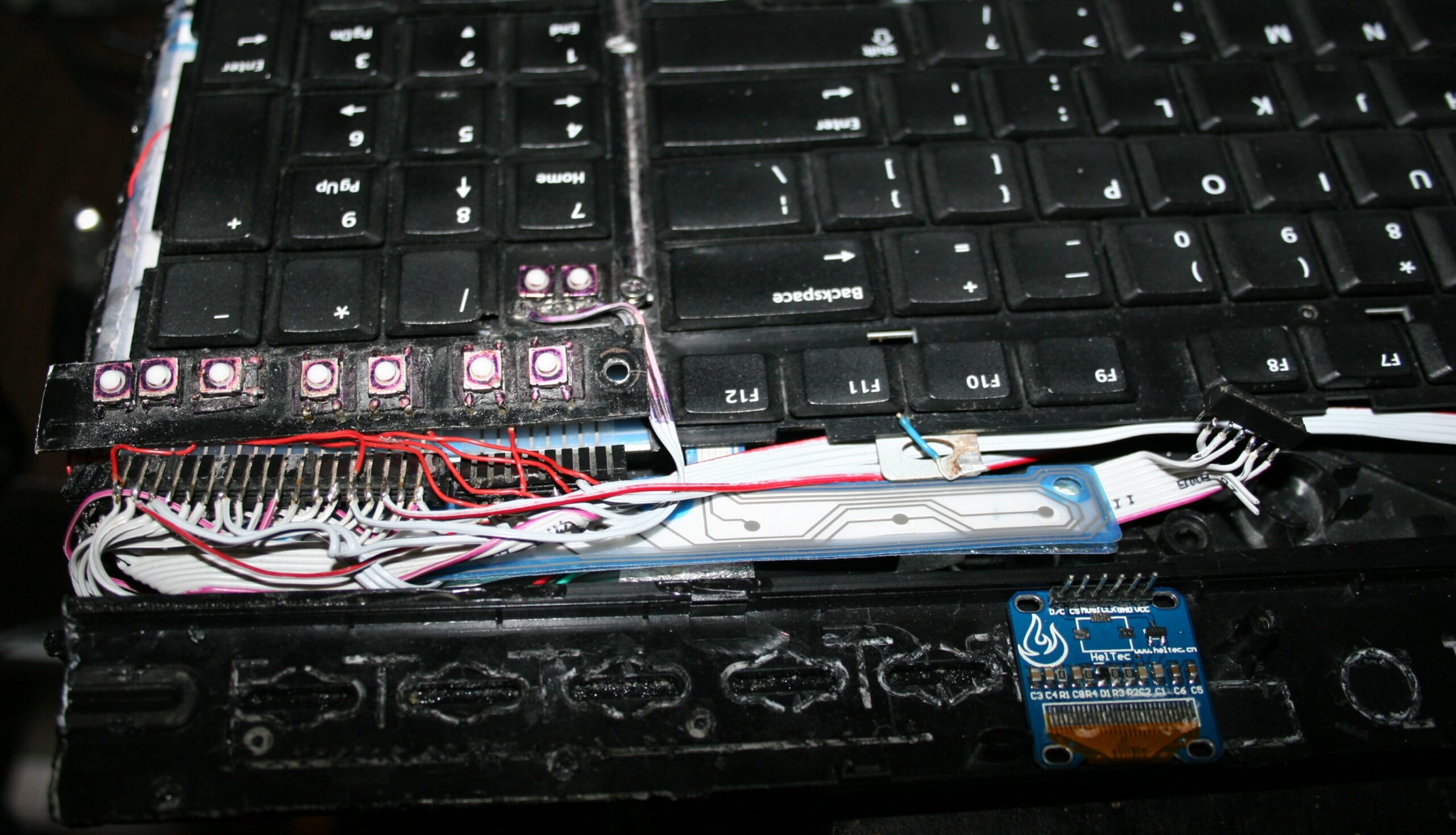
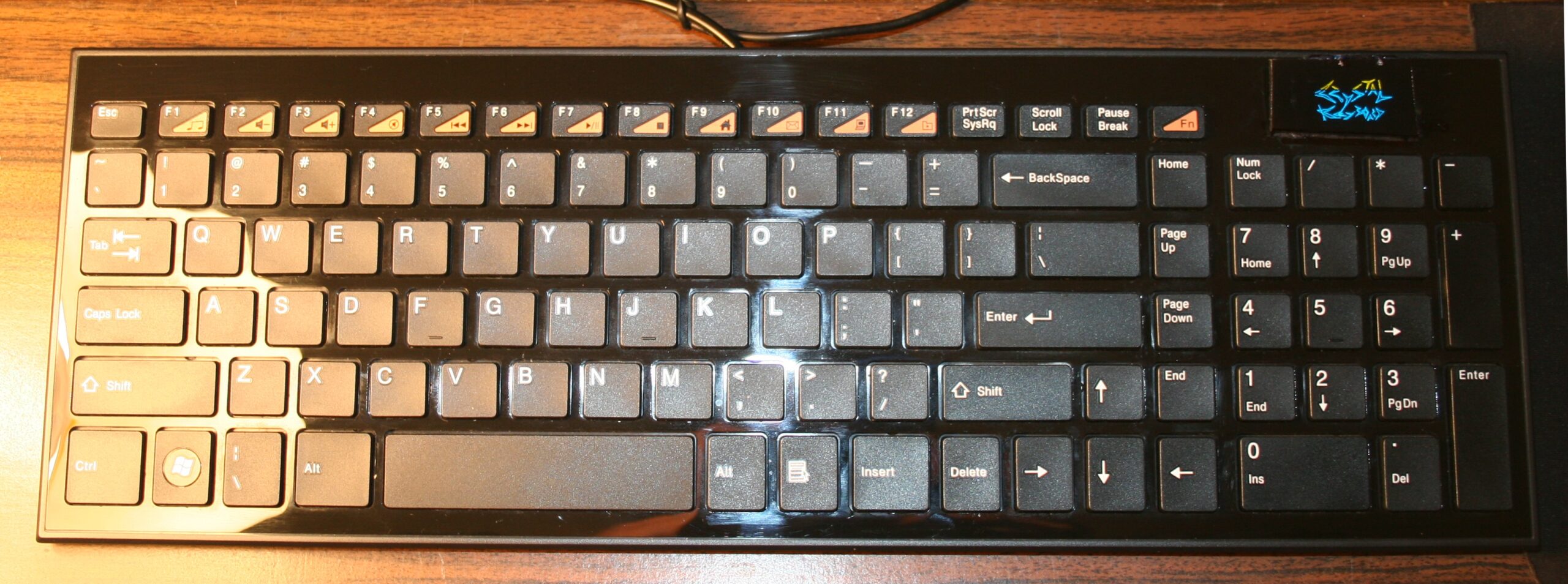
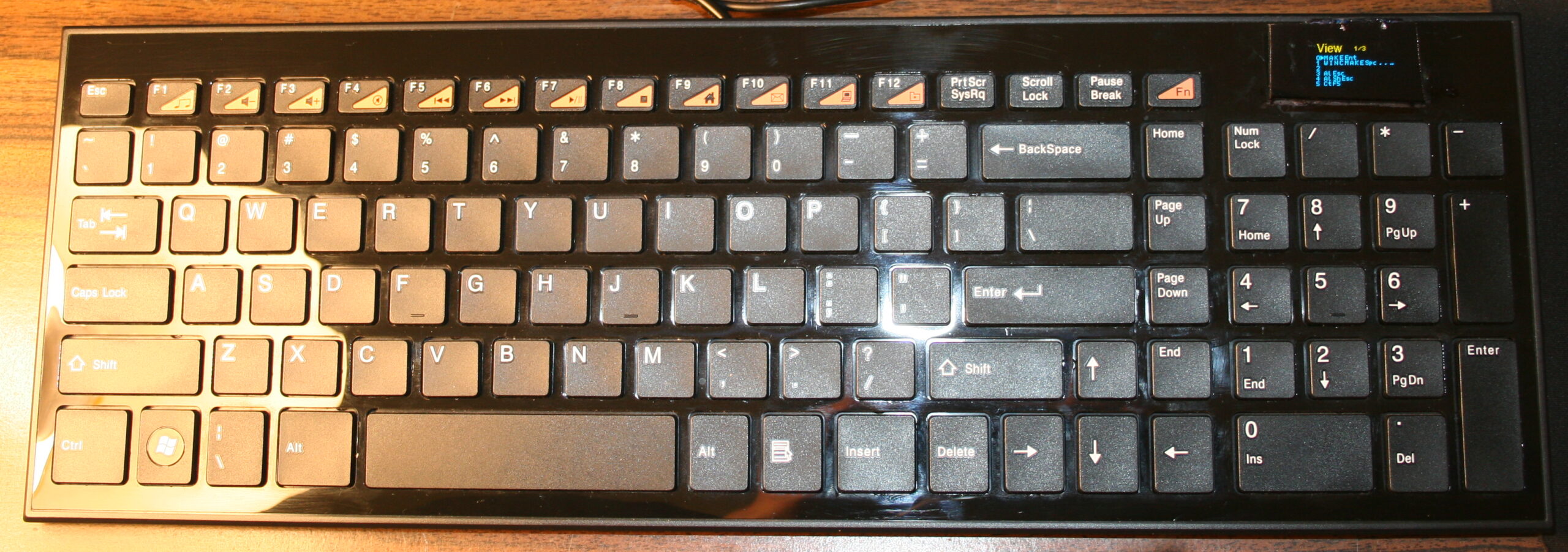
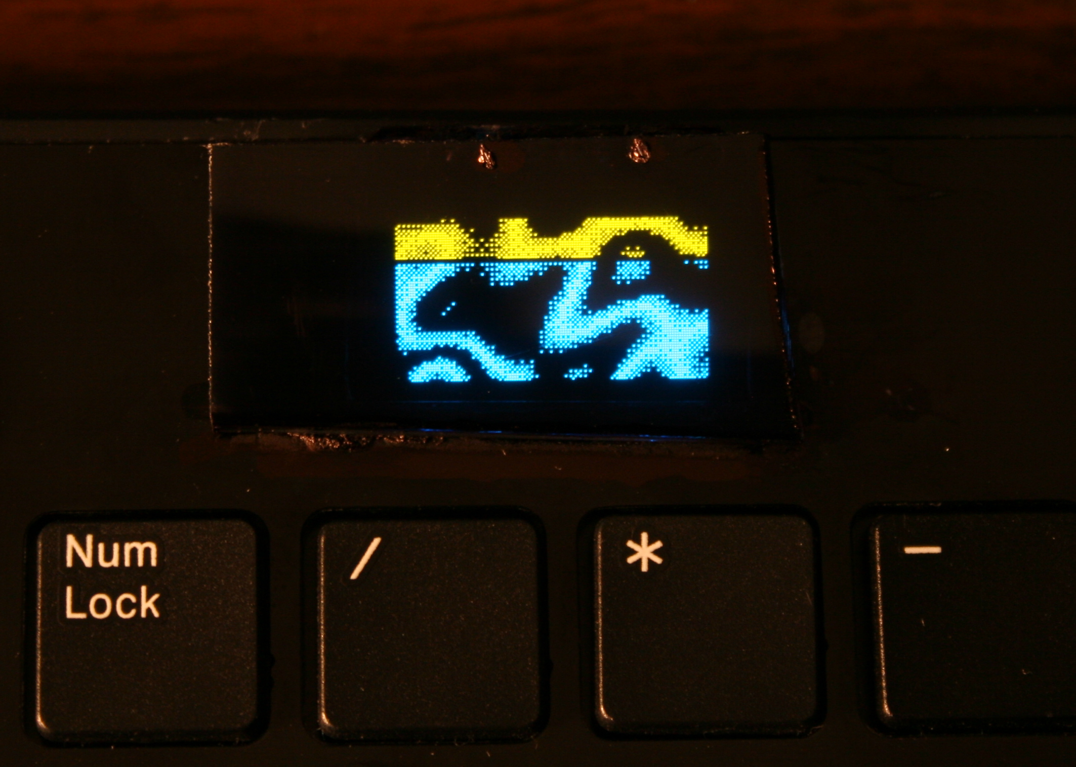
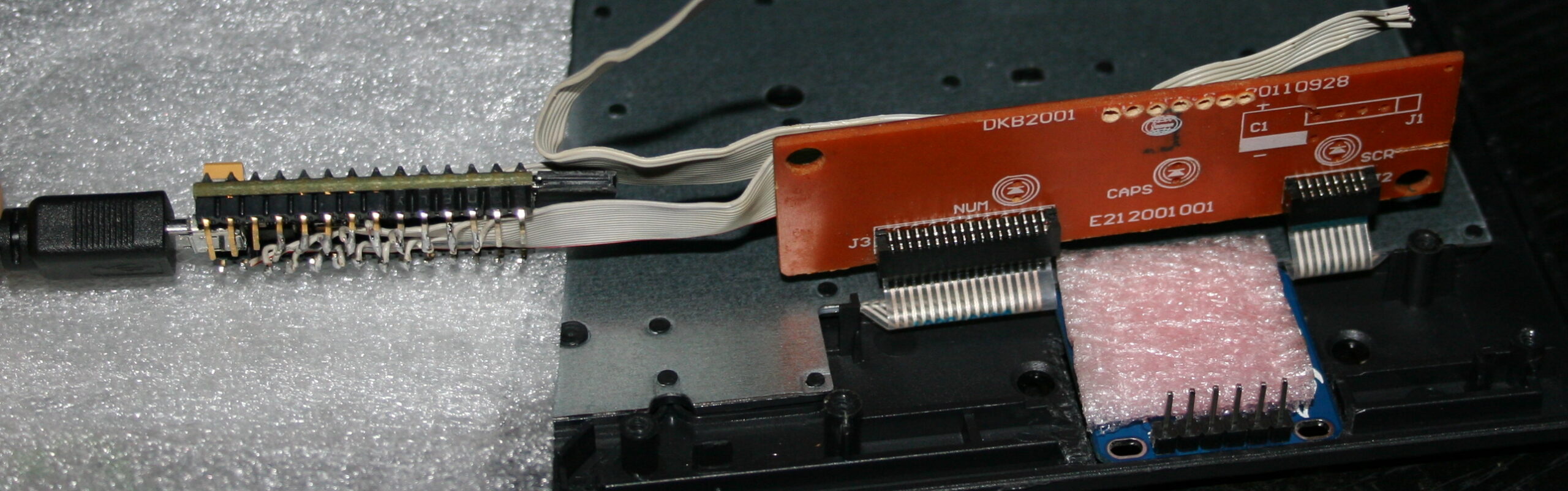
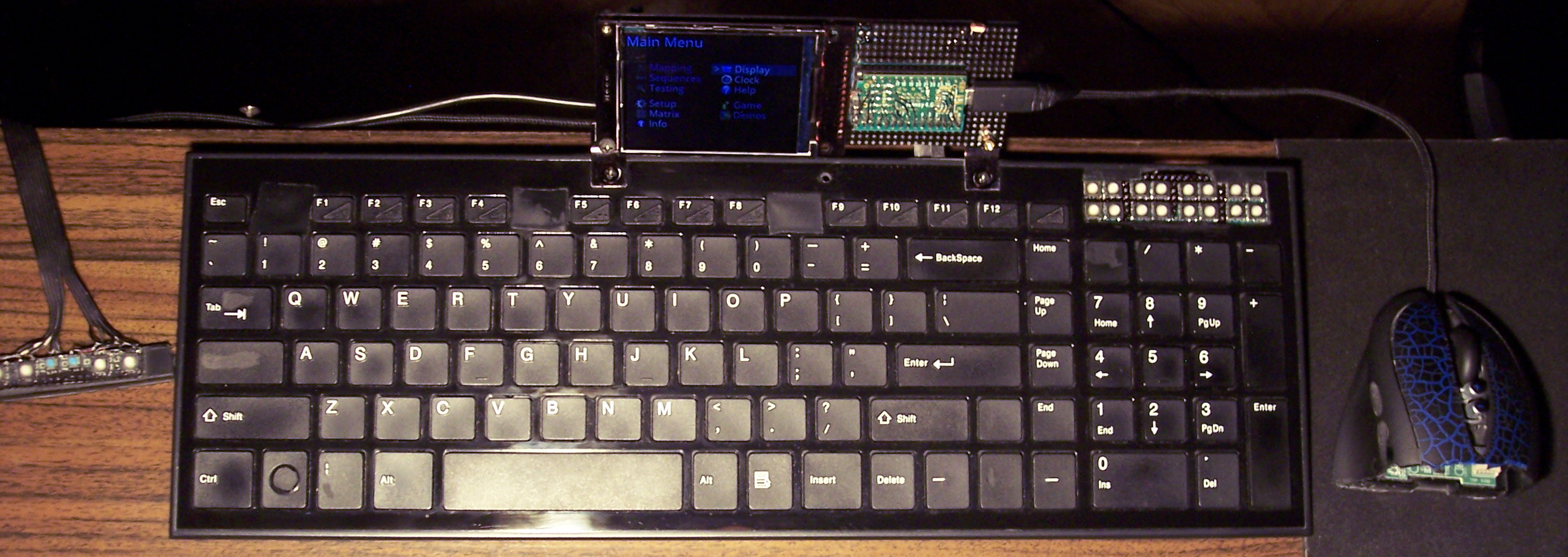
The newer two of my heavily modified keyboards. This time having Teensy 3.1 (or 3.2) as microcontroller with a tiny 1″ monochrome OLED display. Firmware was based on Kiibohd, it was a fork with my extensions. I added display support (with a library), menu for editing e.g. macros/sequences, few demos and a game. I did improve them further in my newer firmware, with bigger display and later made my own in here.
🛠️Modifications
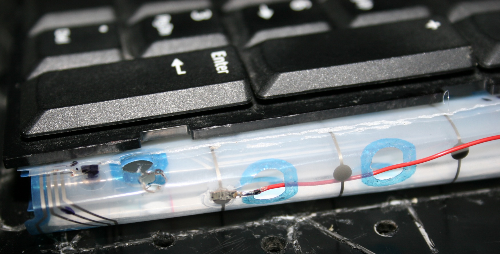
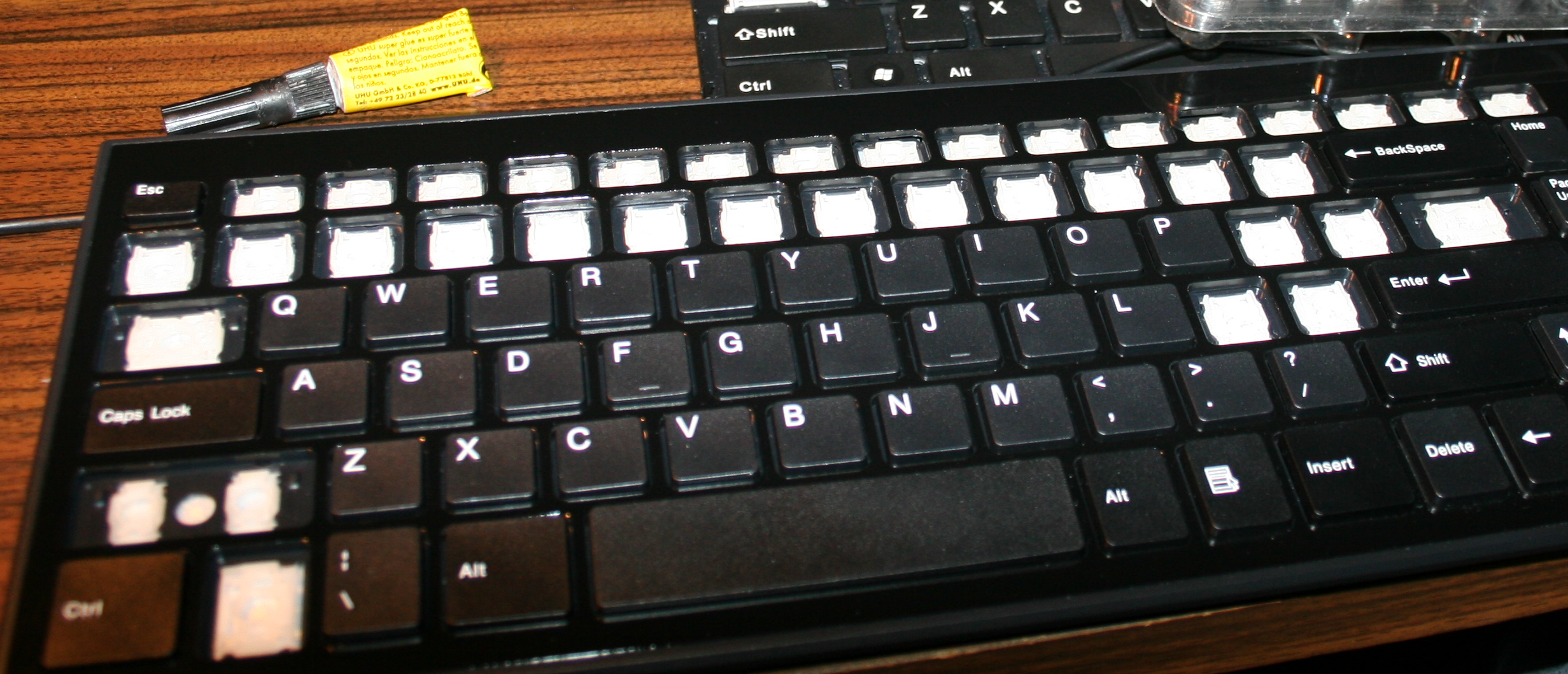
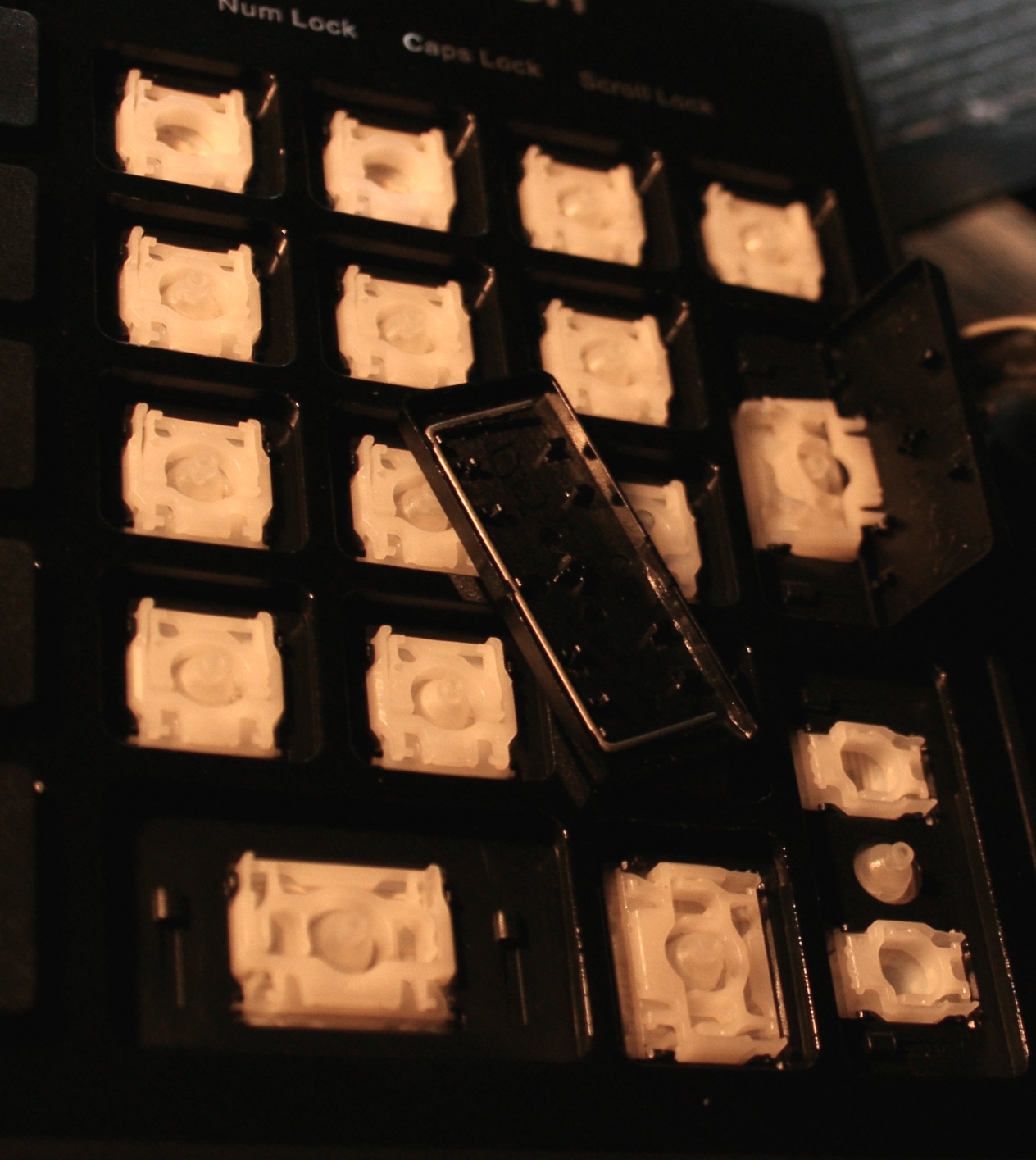
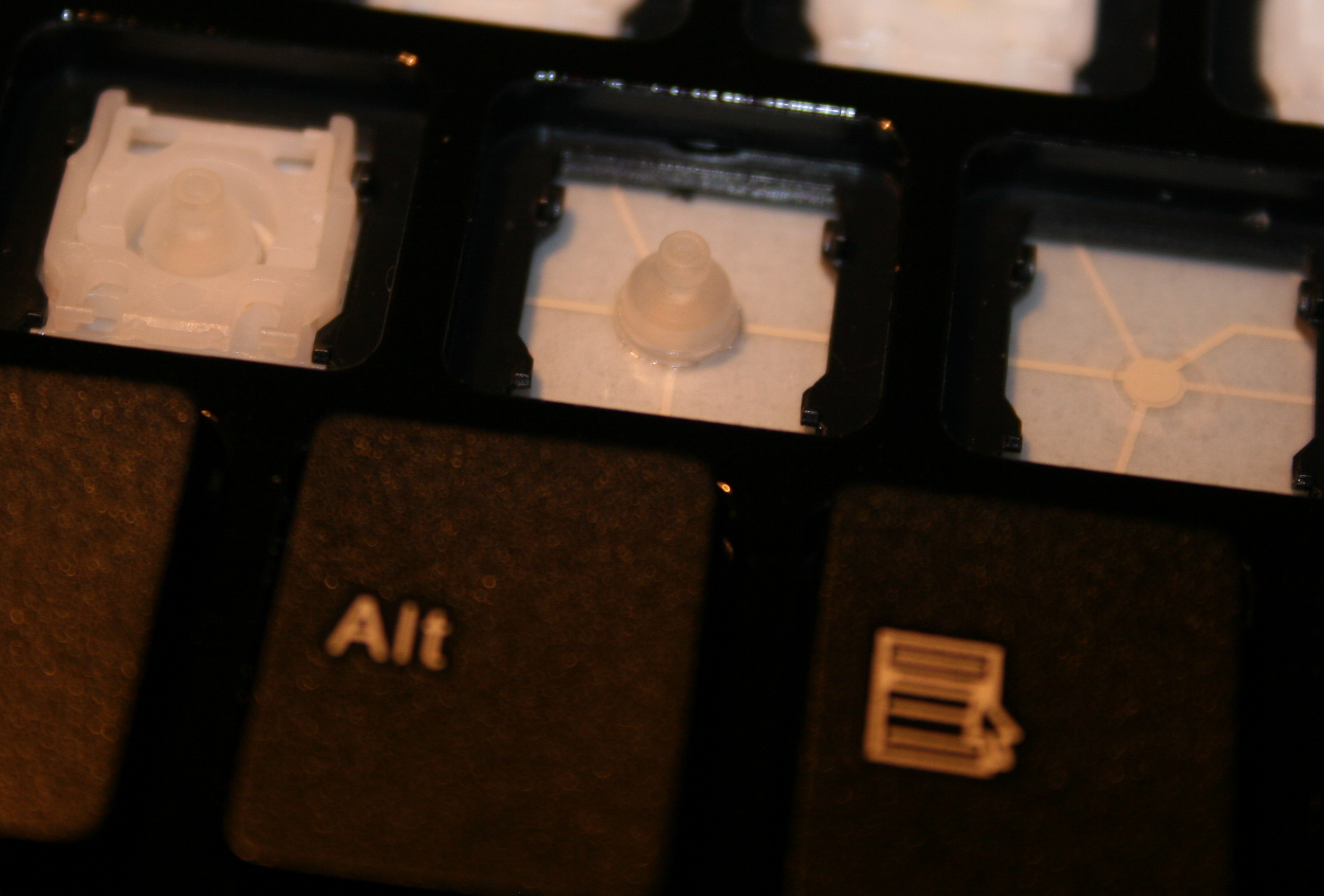
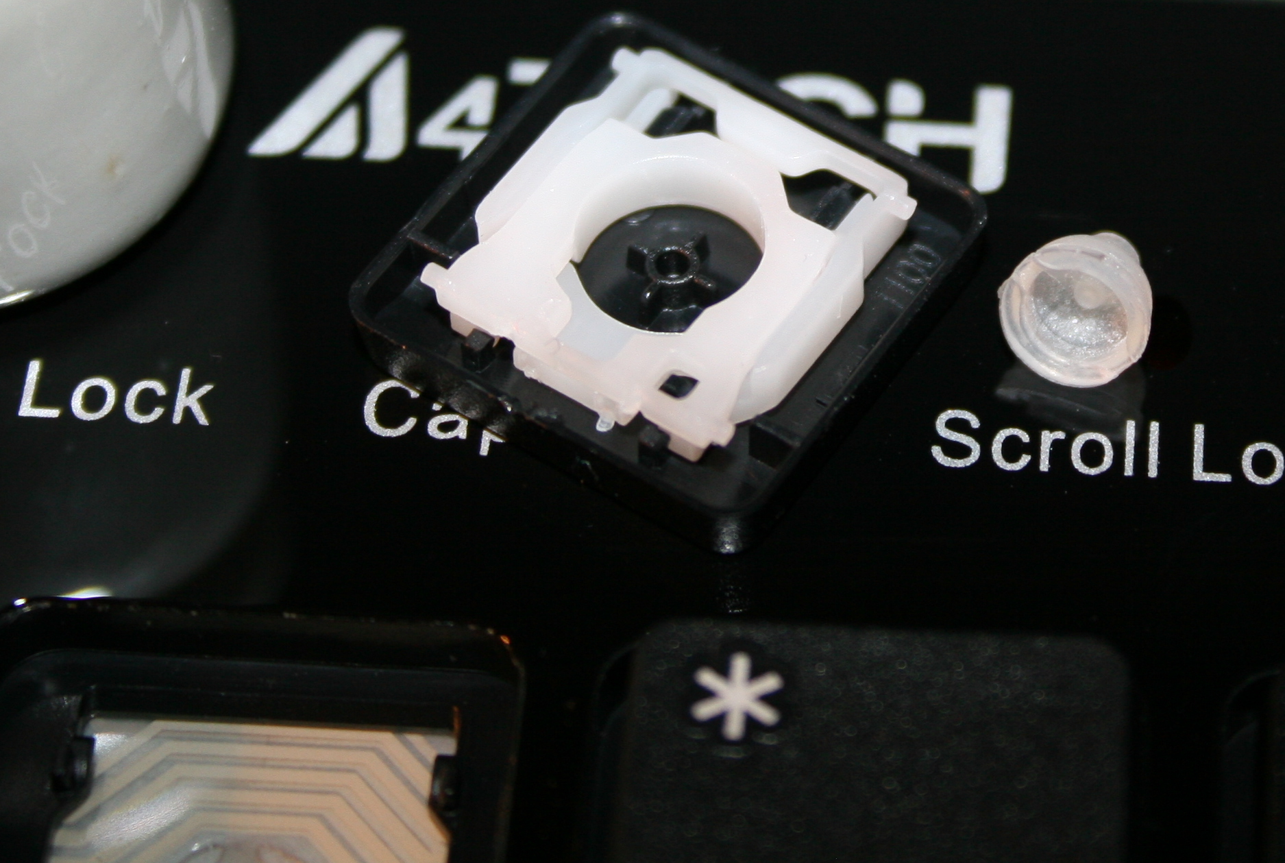
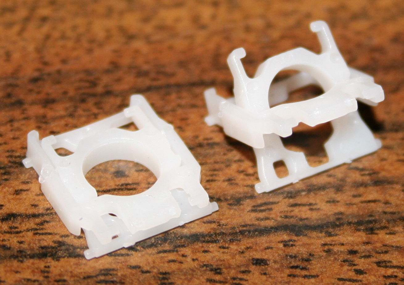
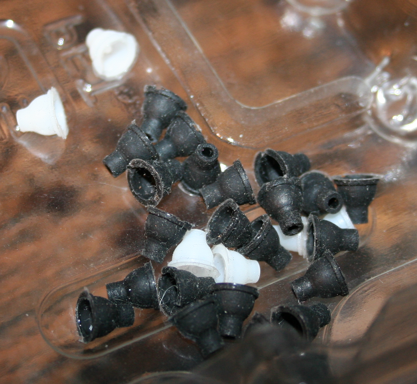
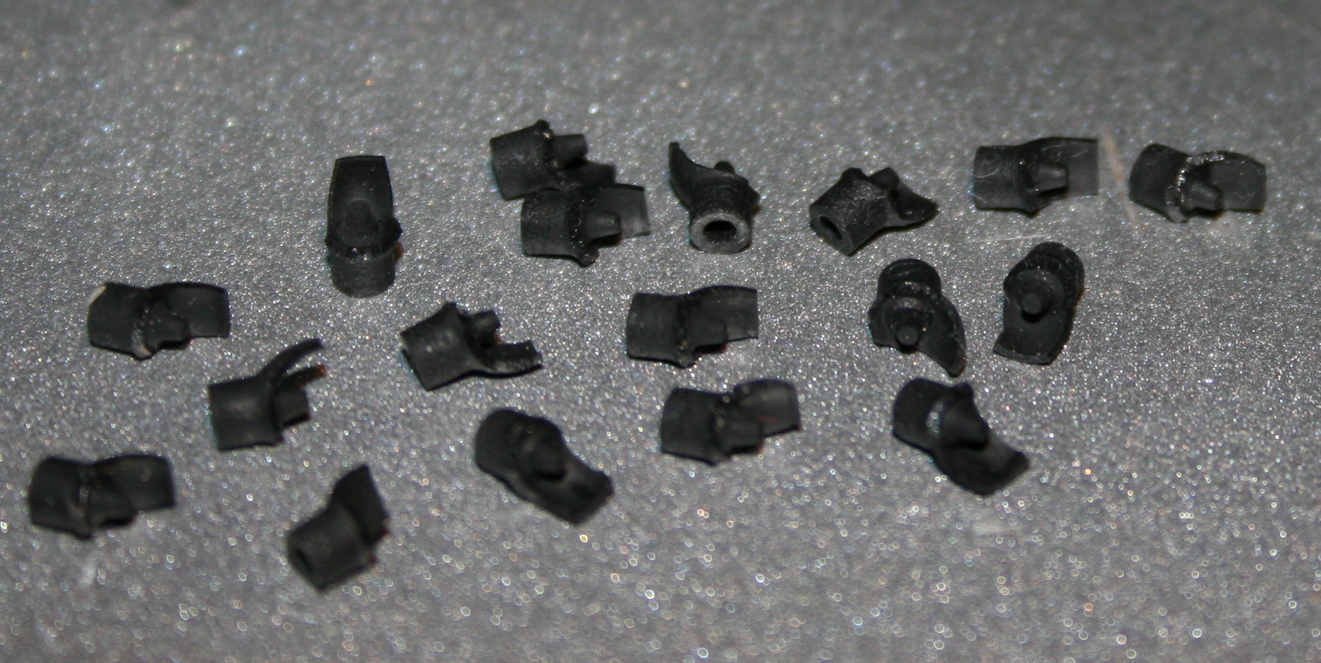
Light press
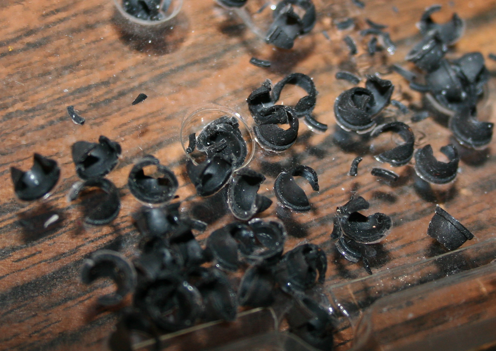
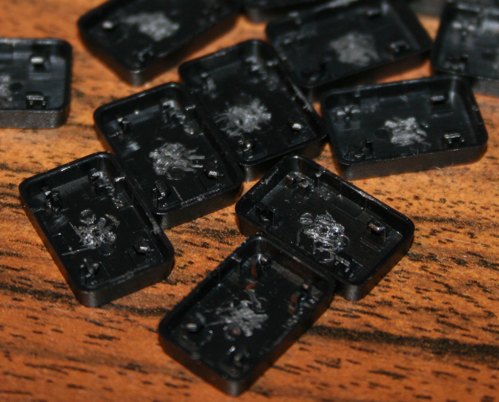
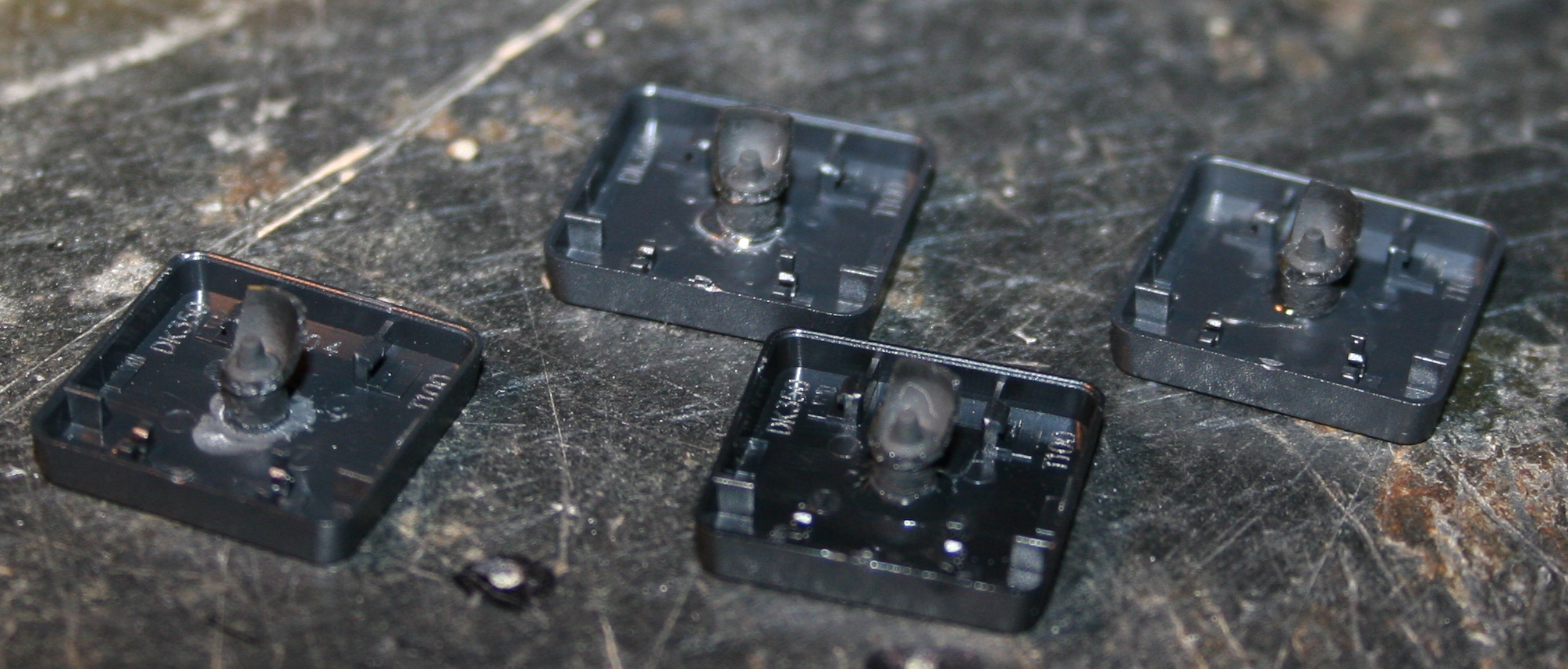
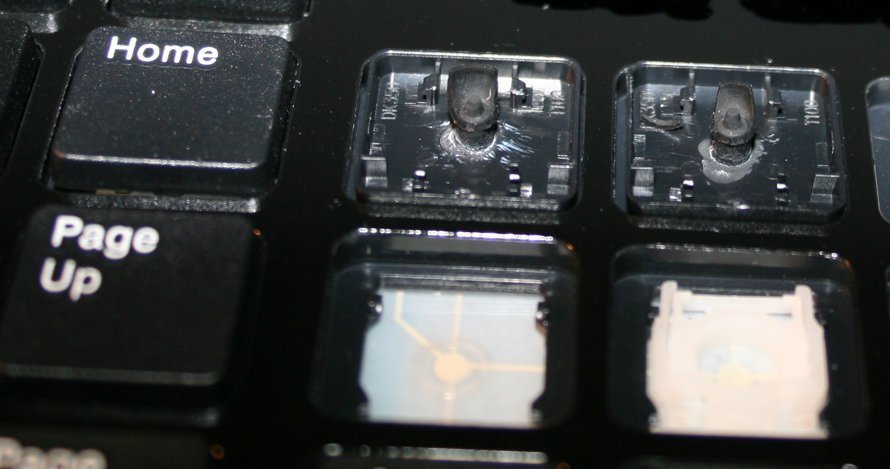
Rubber domes reduction for minimized pressing (actuation) force and distance. Simply more pleasant and comfortable. Also healthier, since the risk of keyboard injuries decreases. I do it always for all my keyboards. Process with info shown here and in gallery below at end.
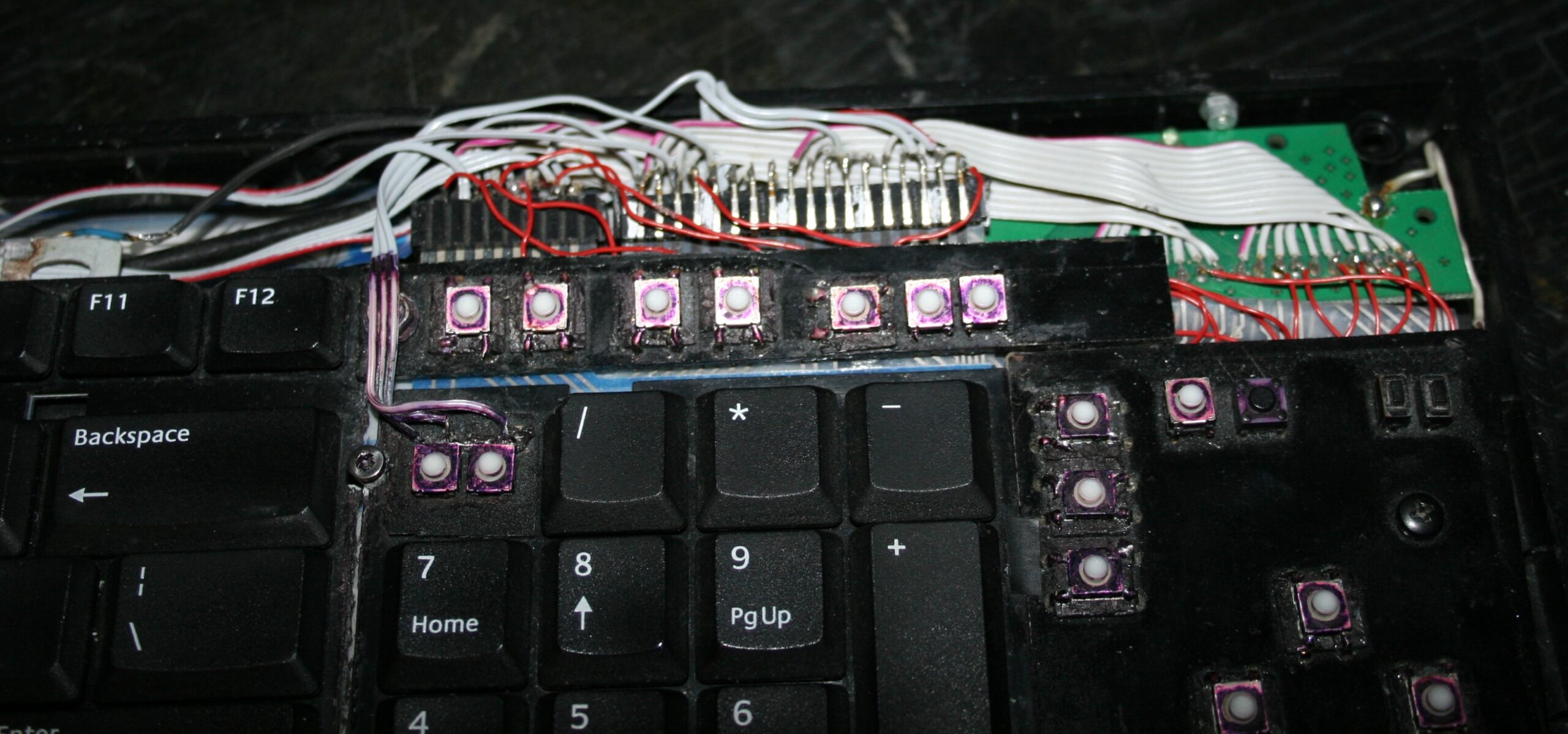
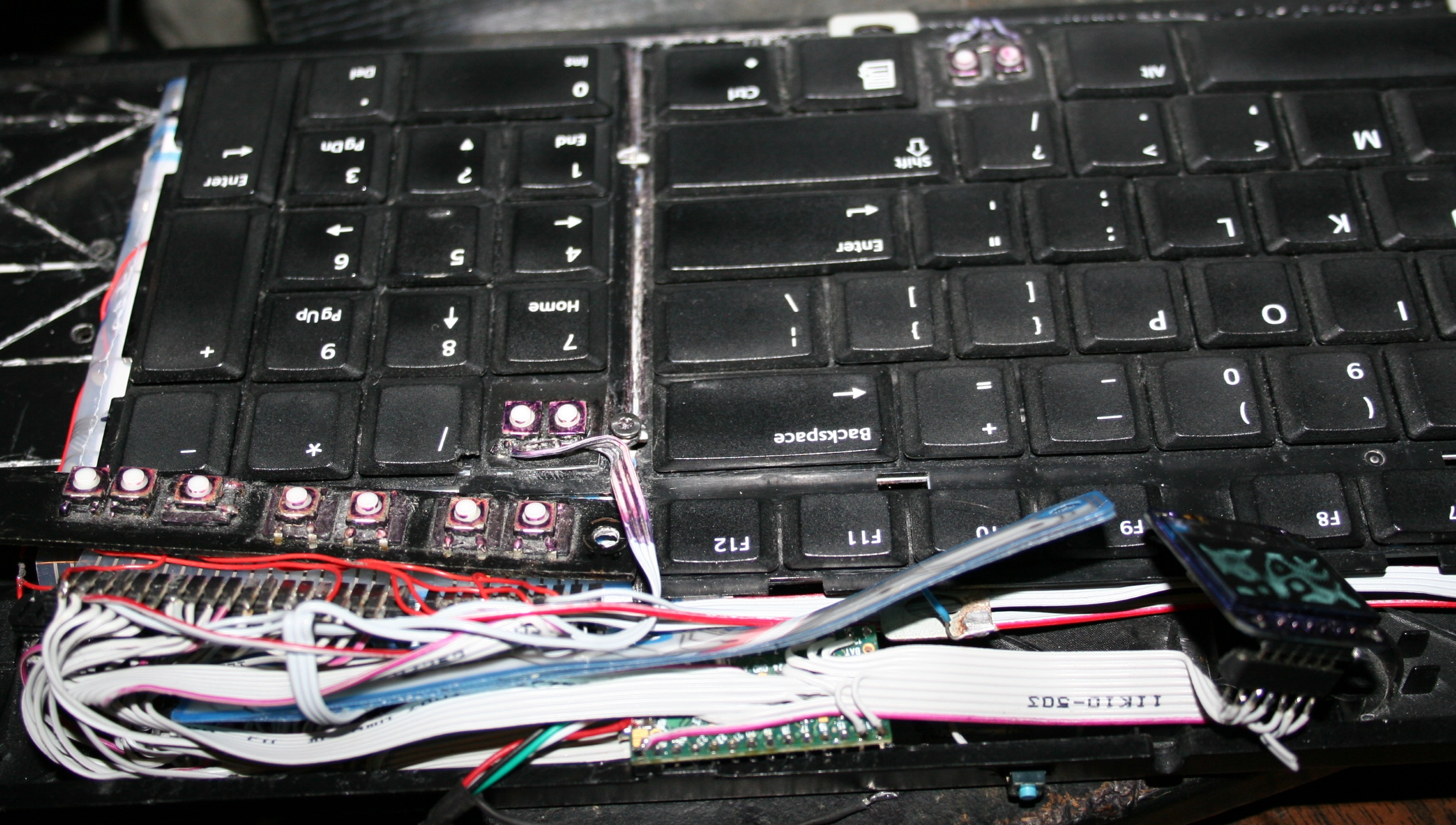
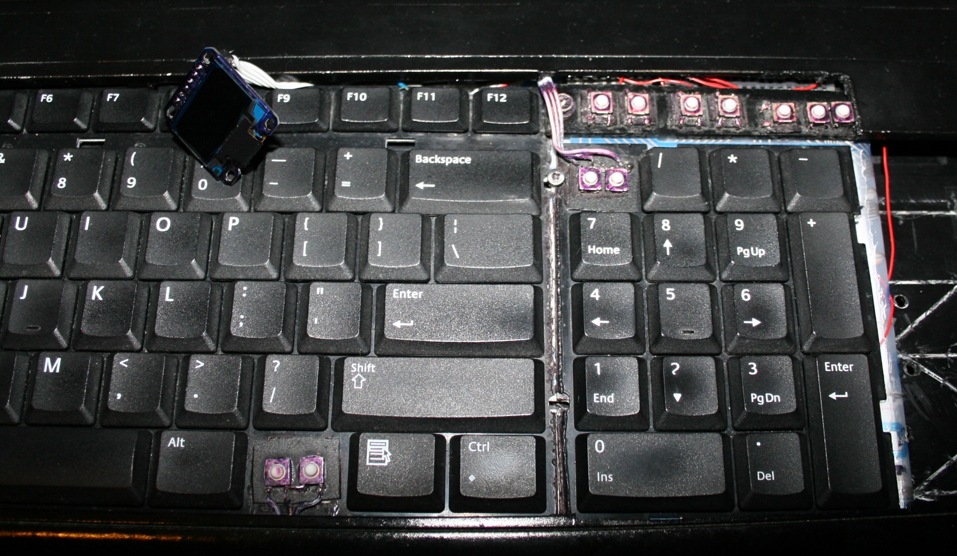
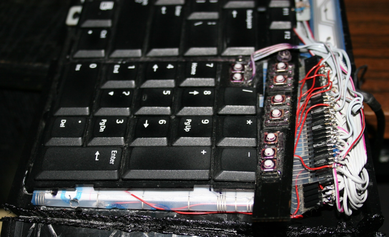
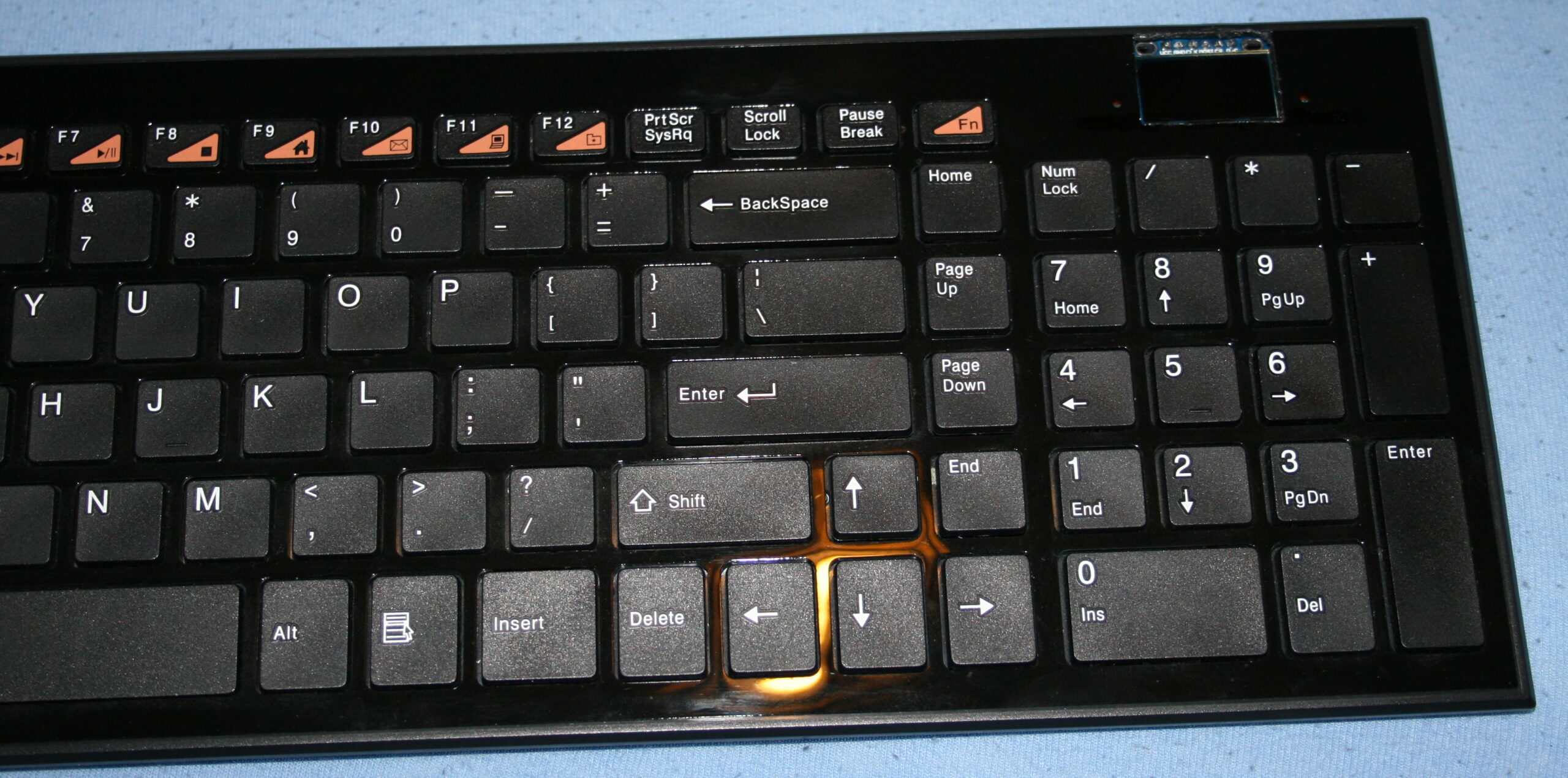
⌨️Additional keys
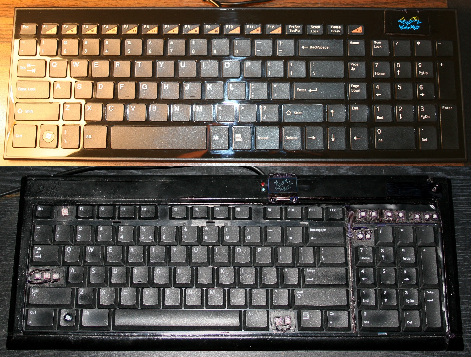
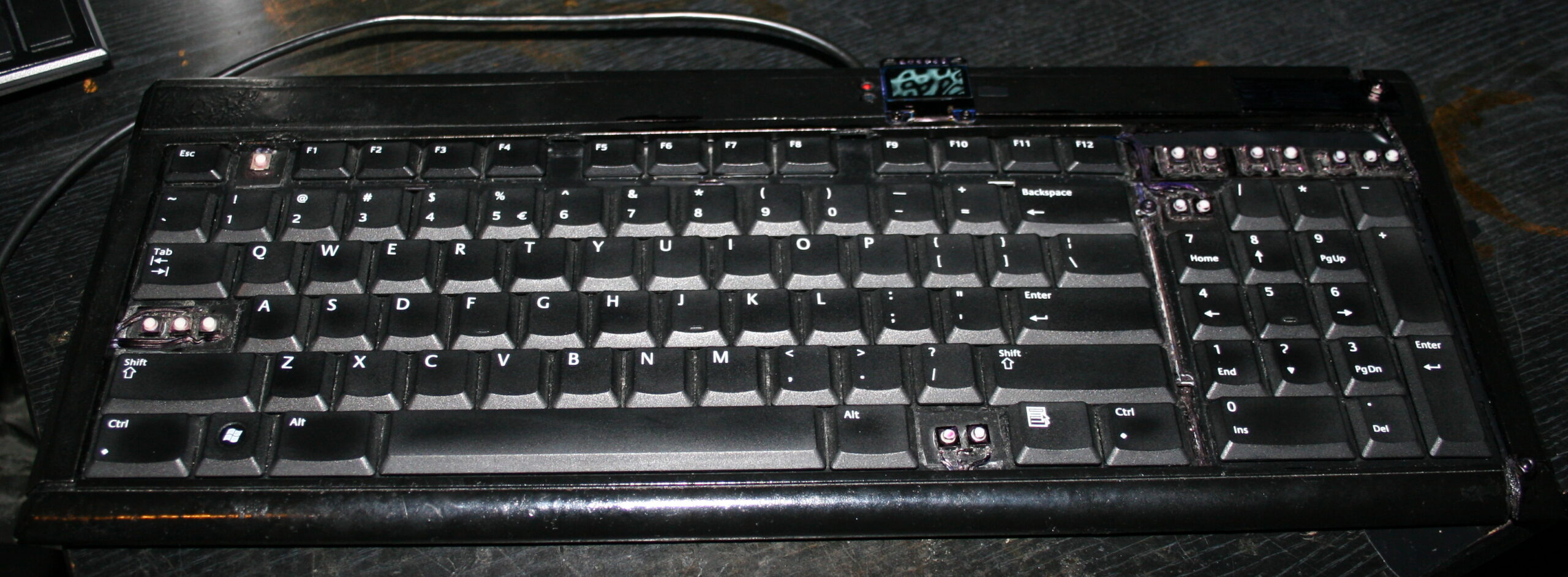
For CK4 there are also few small extra keys. Which were present already in my earliest keyboards CK1 and CK2. Those are glued on top and are made from lightest 0,5N switches available. The row above numpad is used for my audio player control. Rest is custom. This part is optional and I didn’t do it for CK3. The disadvantage is the difference in pressing those switches and much lighter normal keyboard keys. They are smaller so you can fit more, but are less convenient to press. Lastly, regular keys can be used to switch layers instead.
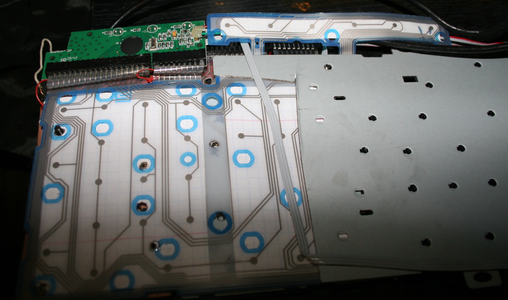
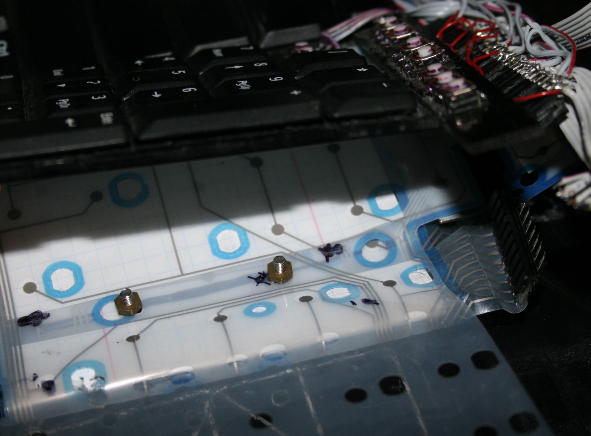
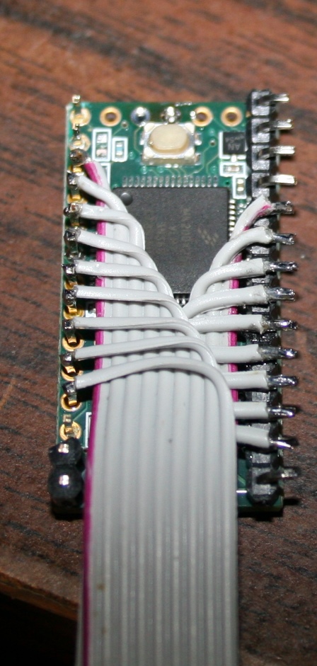
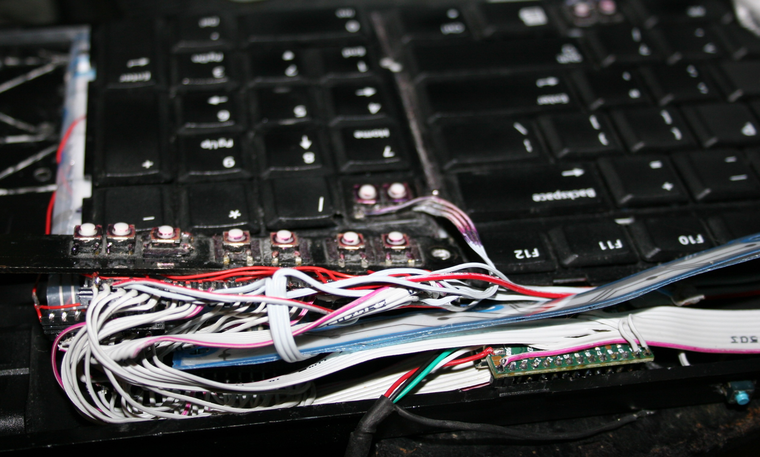
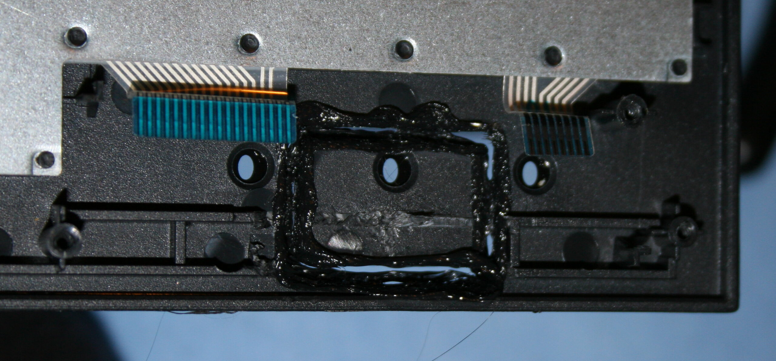
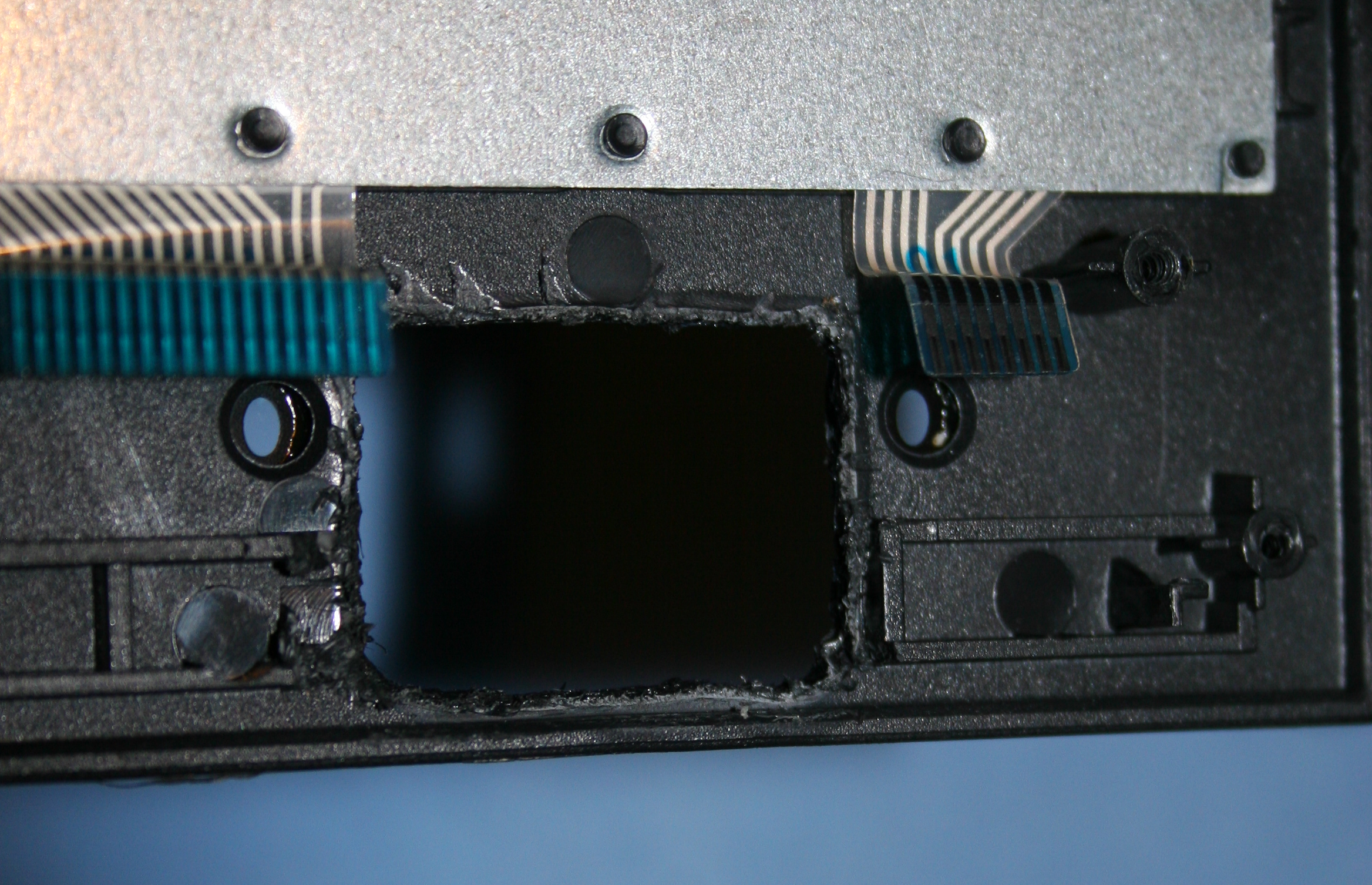
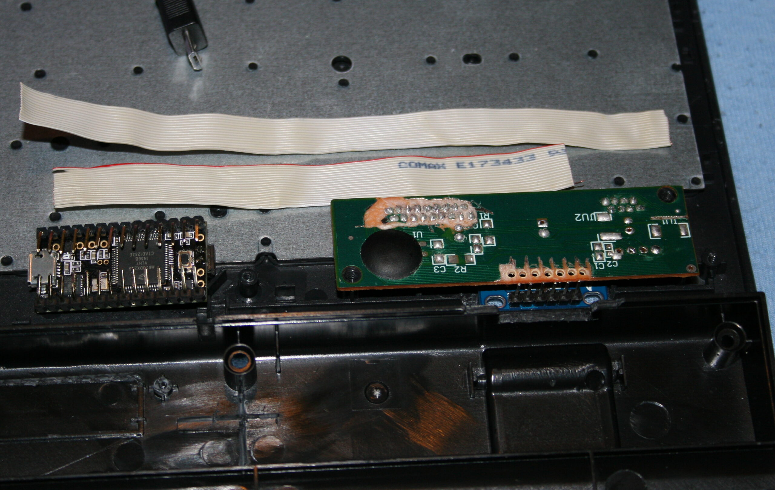
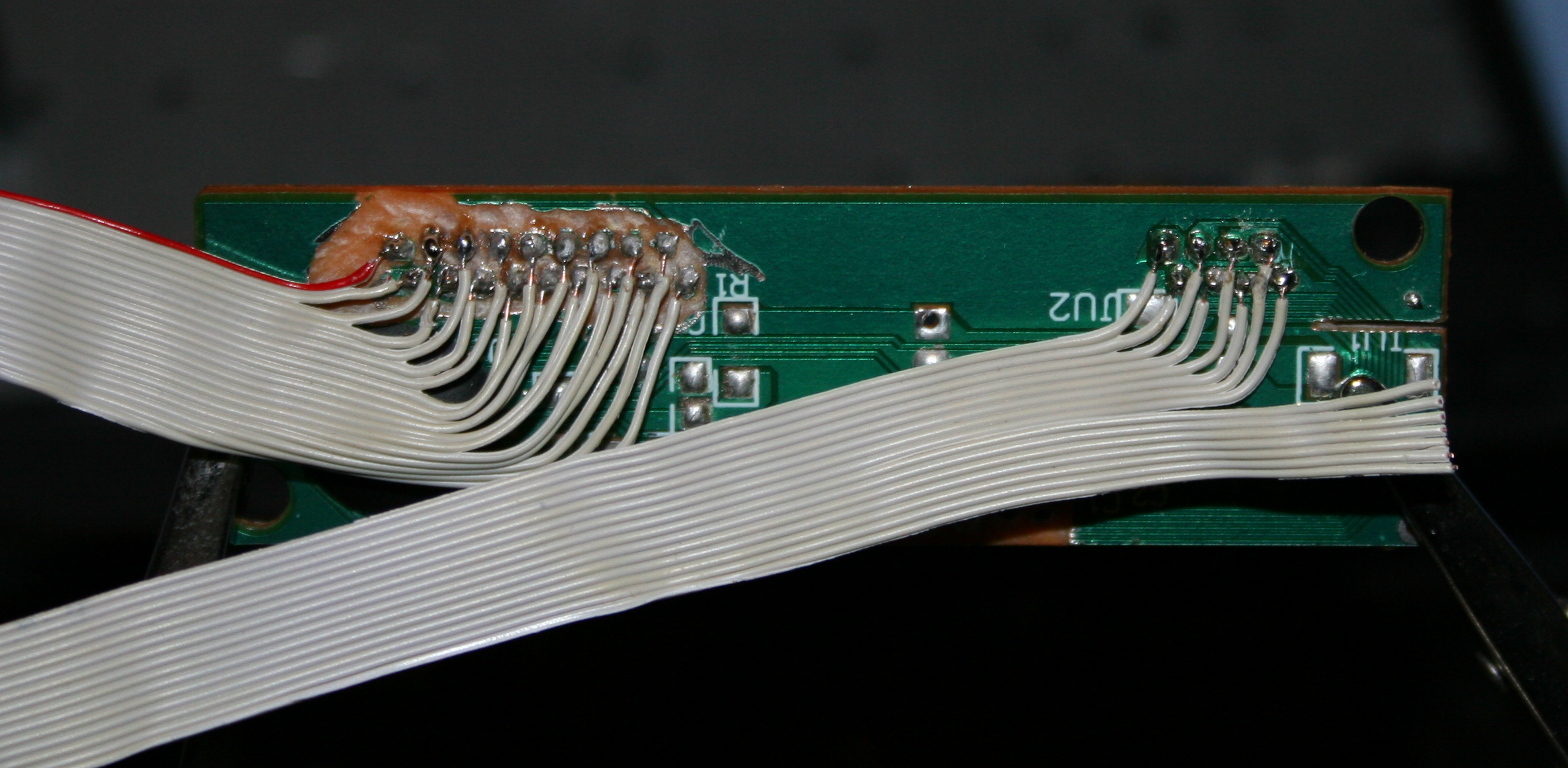
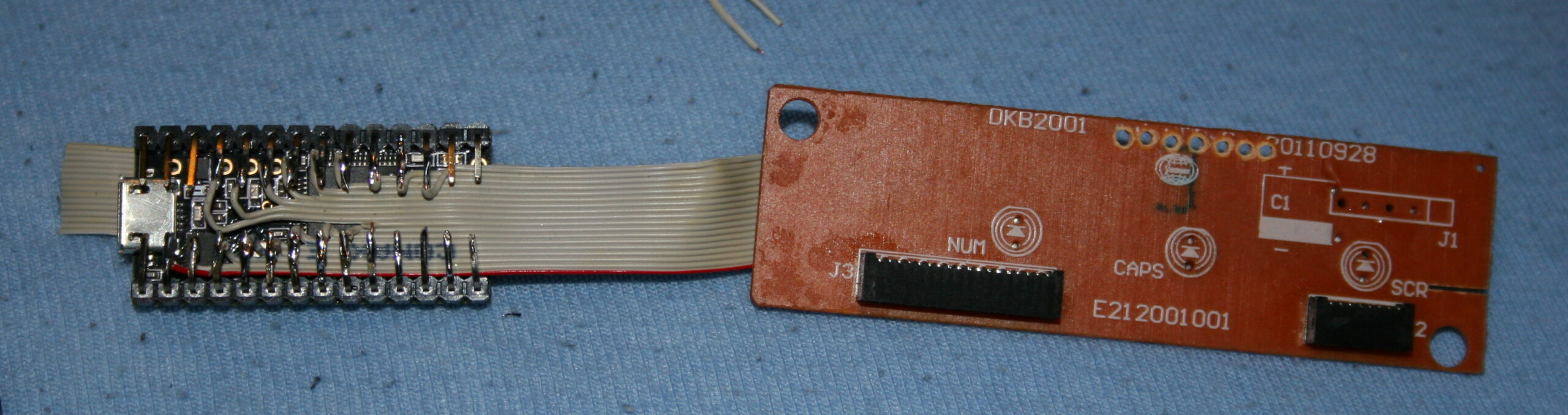
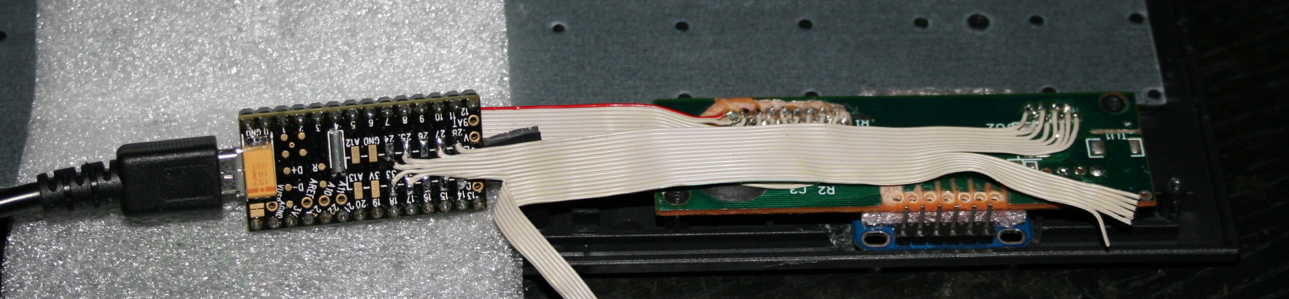
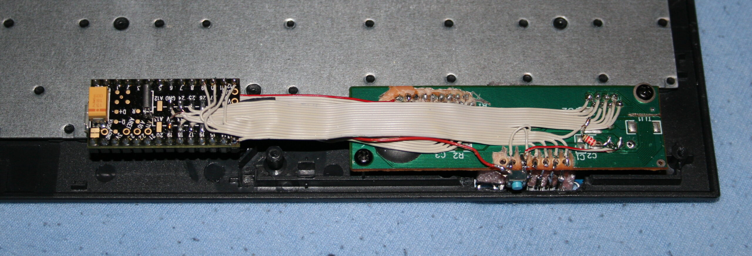
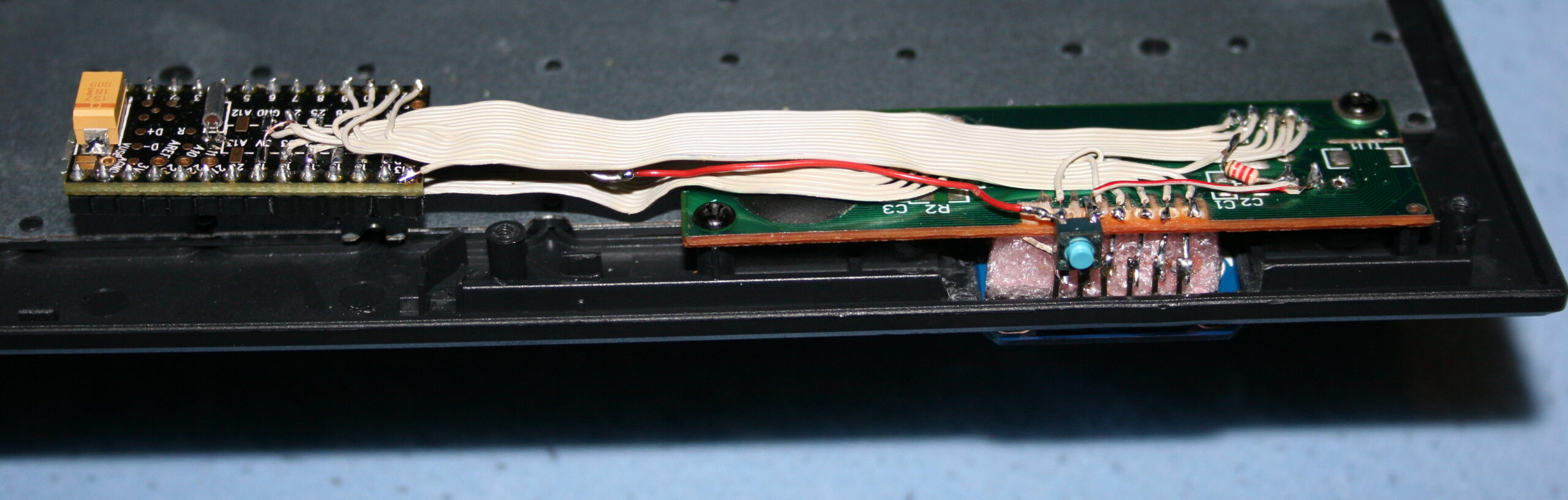
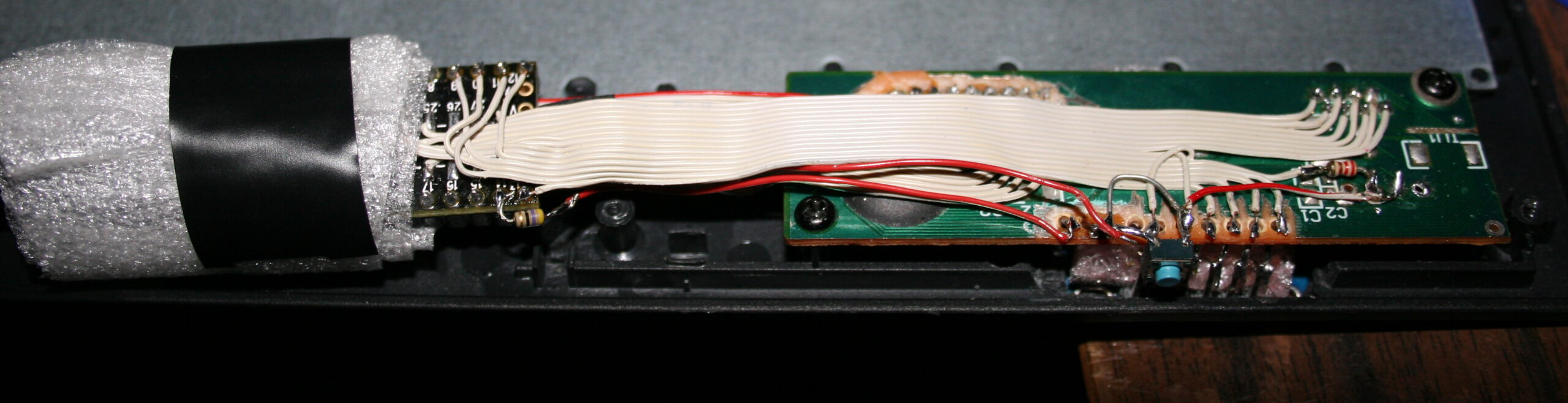
⚙️Microcontroller (MCU)
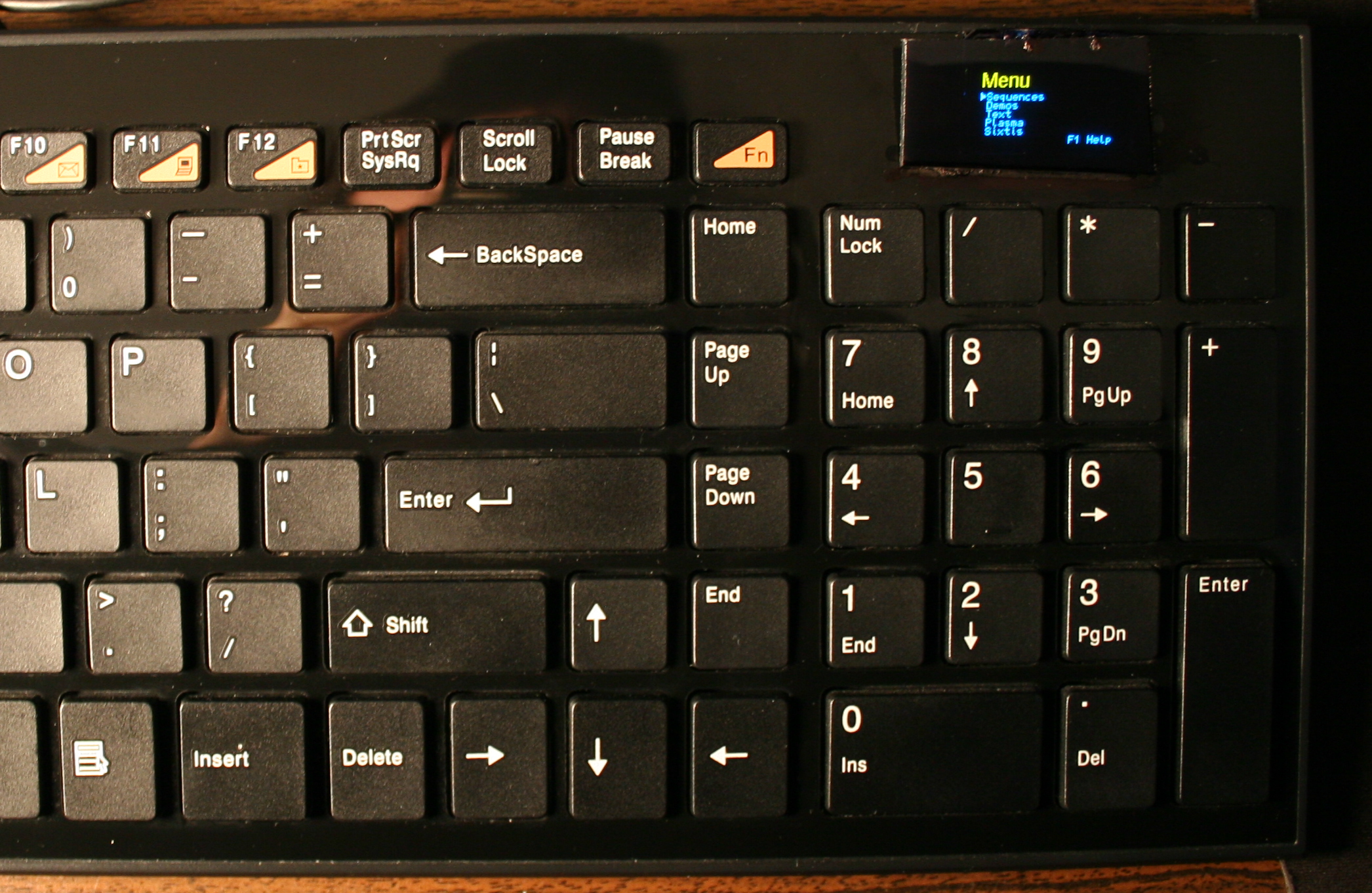
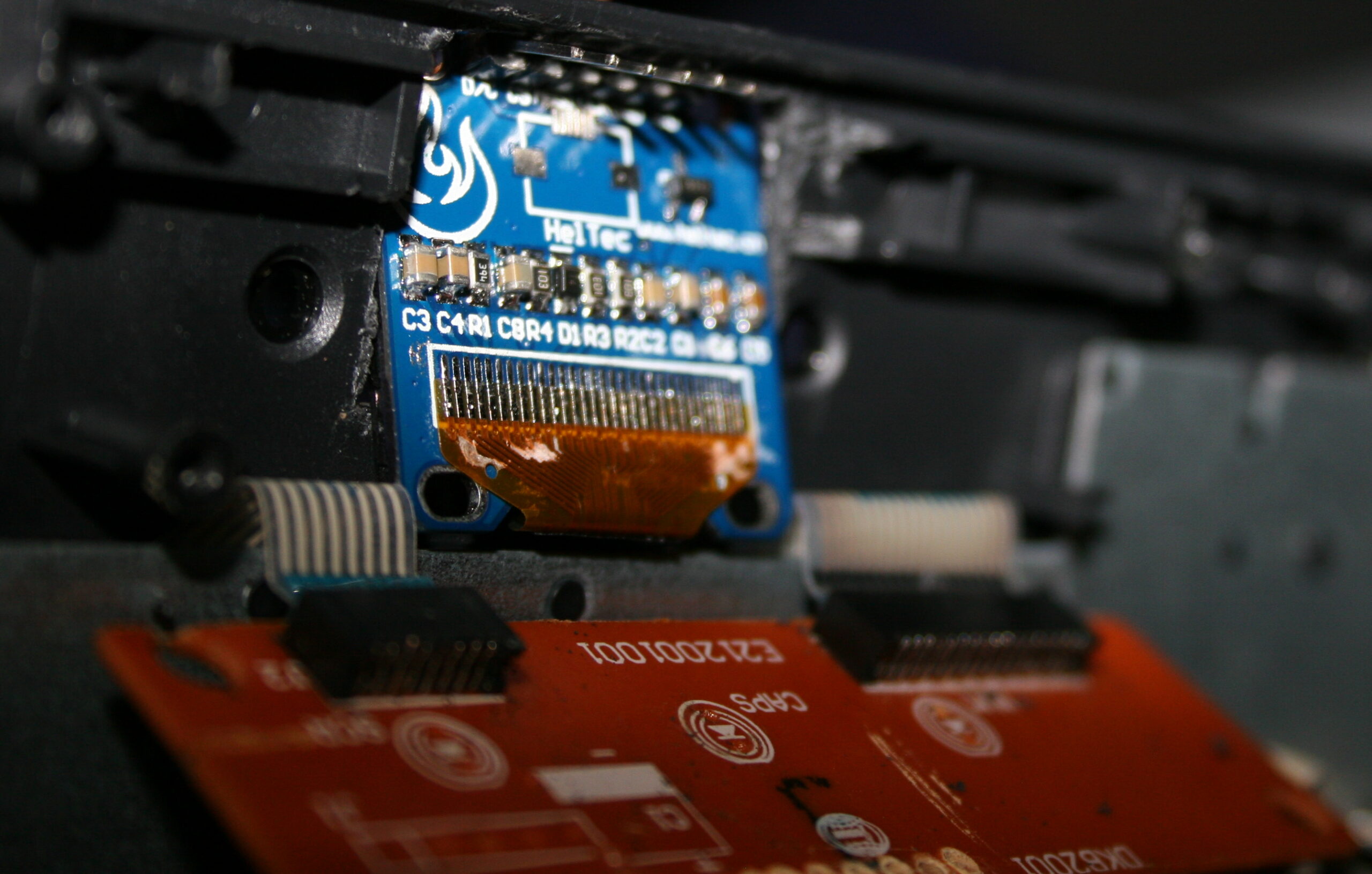
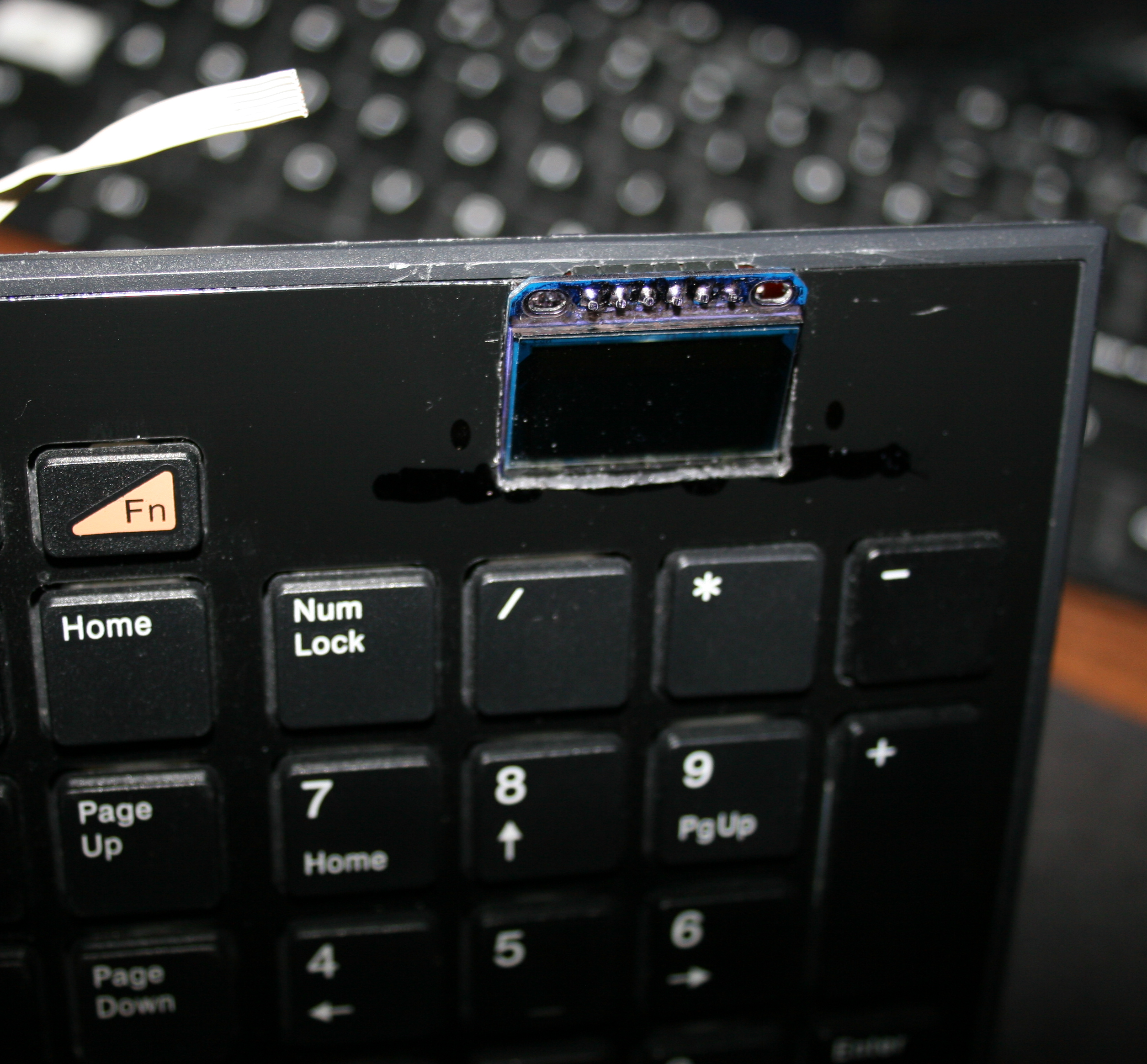
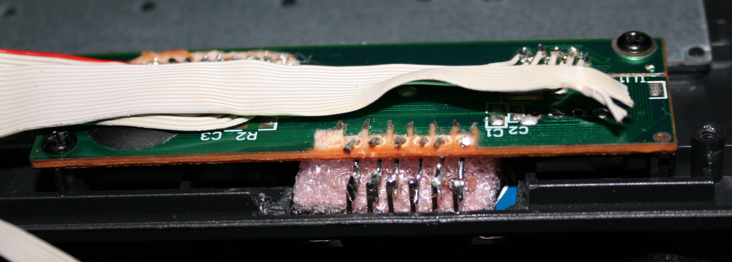
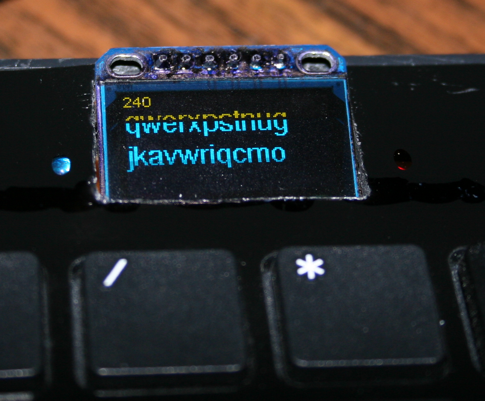
The second step was replacing the keyboard controller board, with my own. The hardware is composed of Teensy 3.1 (or 3.2) with a tiny 1 inch OLED display (SSD1306, monochrome, 128×64) and a bunch of wires to connect to the original keyboard’s matrix.
The reason for this was to take advantage of already made open source Kiibohd controller allowing any imaginable keys assigned and layers. Also possible are macros, key combinations and even mouse buttons and movement simulation. But changing any of this required rebuilding controller software and uploading to controller, through already present USB. Which is a major flaw for me.
📊Features
After getting it to work, I implemented my own menu where you can edit sequences, stored in memory (remembered after power off). The sequences are very useful for not typing passwords or simply binding some useful macro combinations or commands dynamically. Which needed a display and menu for entering.
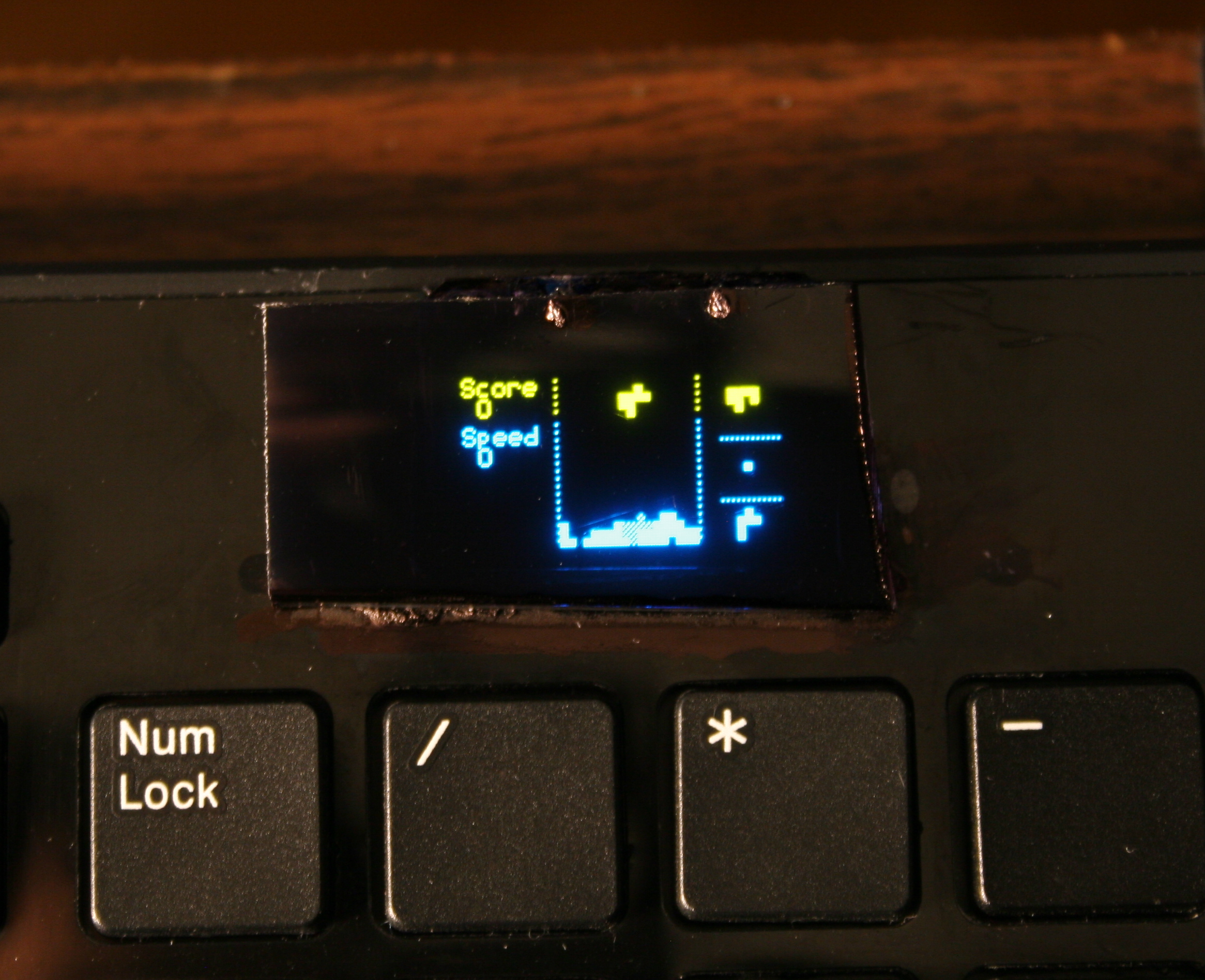
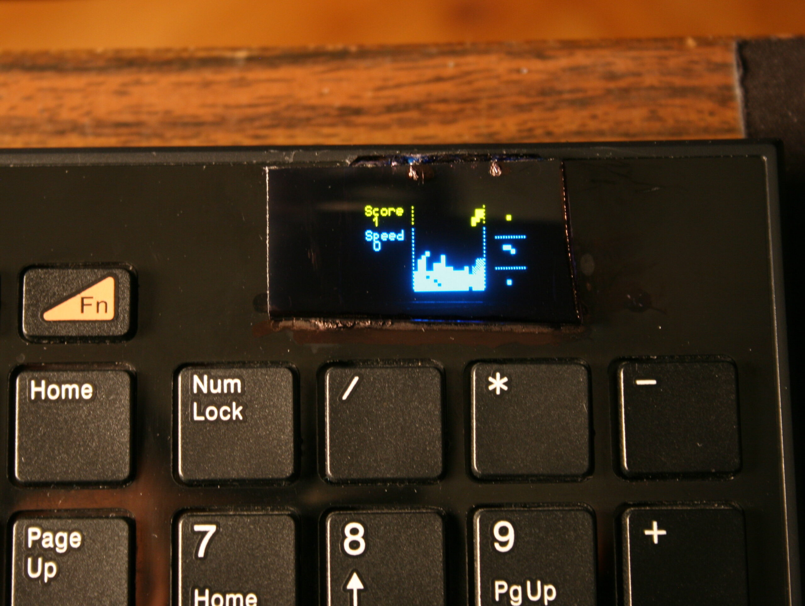
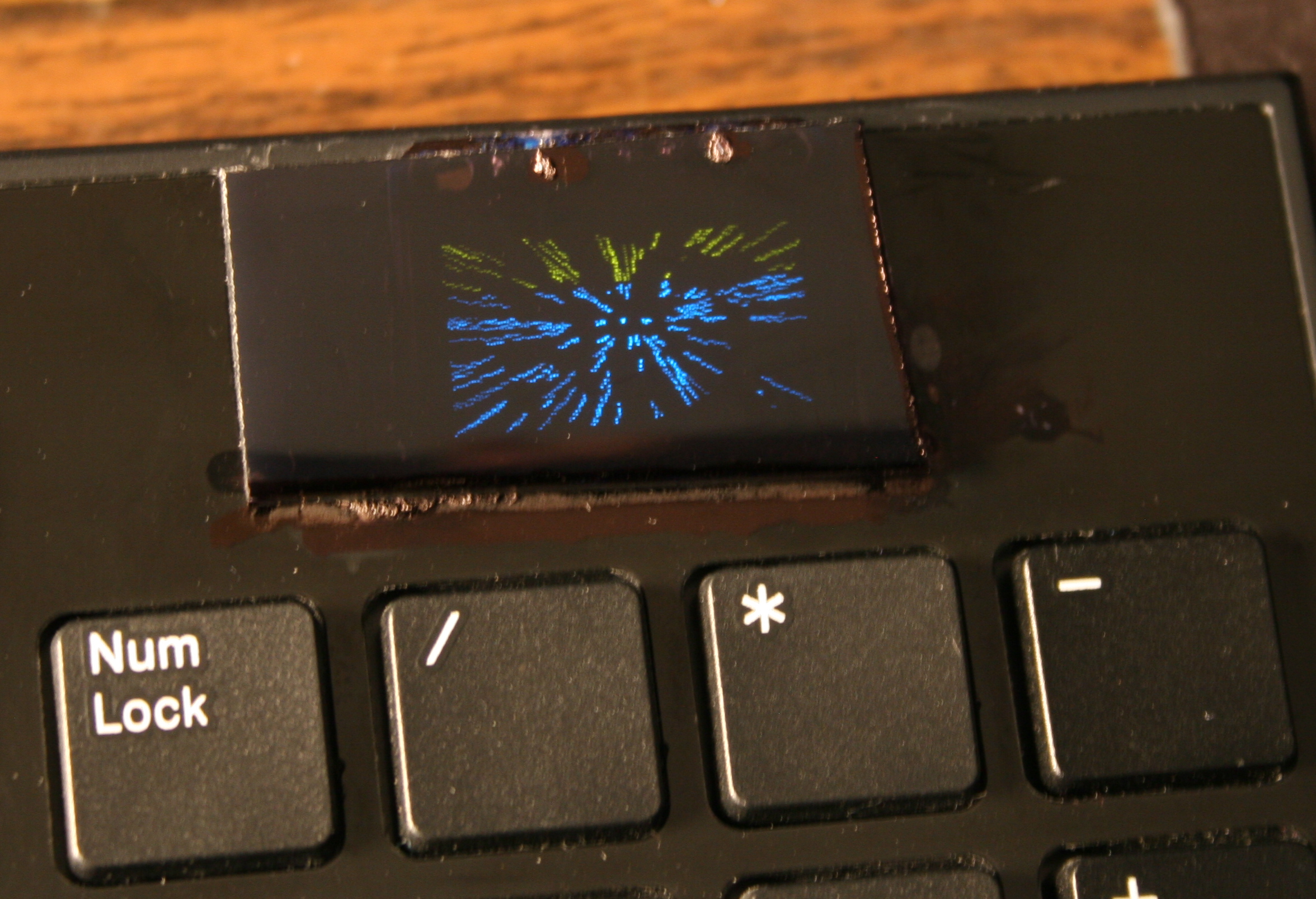
Once I’ve done the useful stuff, I got carried away and implemented several demos on display and even a falling blocks game. I also wrote about it in this forum post.
📂Sources
The code is in my fork here with some more detail. IIRC it can’t build anymore.
⌛Conclusions
It was a bit simpler to start at the time, instead of writing completely my own later on bigger display. Since the display was so tiny I didn’t yet think of drawing all keys on it. And making them rebindable on display, instead of following the way all other FOSS controllers I knew did, that requires rebuild and upload which is way slower.
✅Summary
For reference, here is a table with current status of all my keyboards, since start until present day:
Name
Assembly year
Original keyboard
Keys actuation
[gram force]
Notes
CK3 > CK6 > CK9
2016 > 2018 > 2020
A4 Tech KX-100
23 g
Cheaper, bit wobbly, but more keys
CK2 > CK4 > CK7
2005 > 2016 > 2018
Logitech Ultra X Flat
33 g
Stiff foil, old, extra keys
CK5, CK5b
2015, 2020
A4 Tech KV-300H
9-18 g
The lightest foil
CK1
2004
Logitech Ultra X Flat
25 g
First, old, had extra keys,
now only for testing, 1 row dead 💀
▶️Videos
CK3 demos, CK4 demos – showing all demos on display, it is only 128×64 resolution
Plasma – uses dithering, since display is mono, 1 color only
Game – blocks falling, shortly played on each preset
Features – menu with all configuration possible back then and options, also keyboard view


