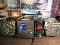
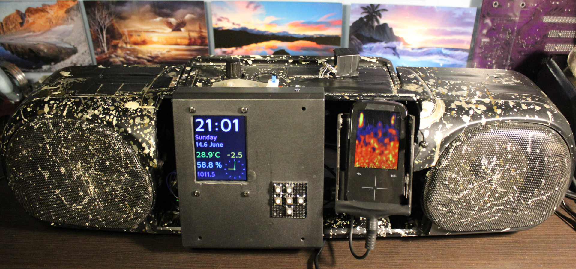
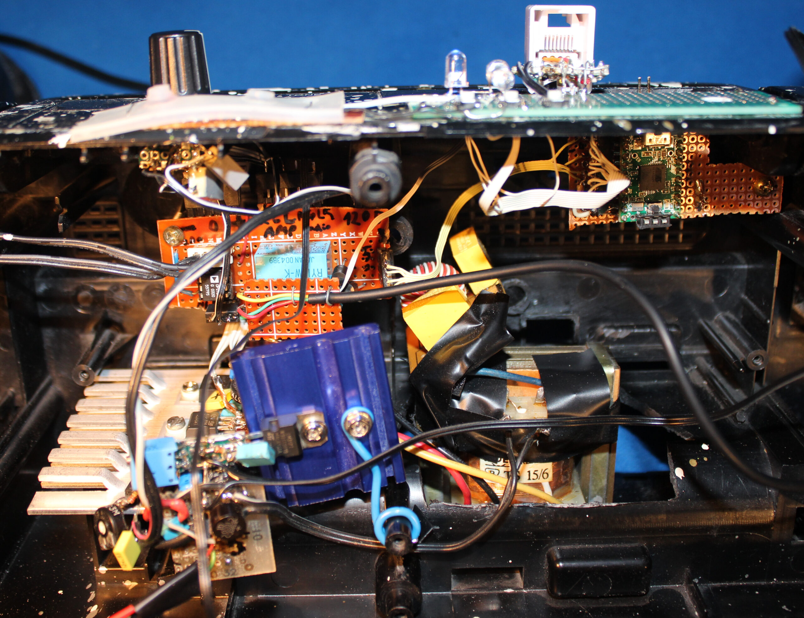
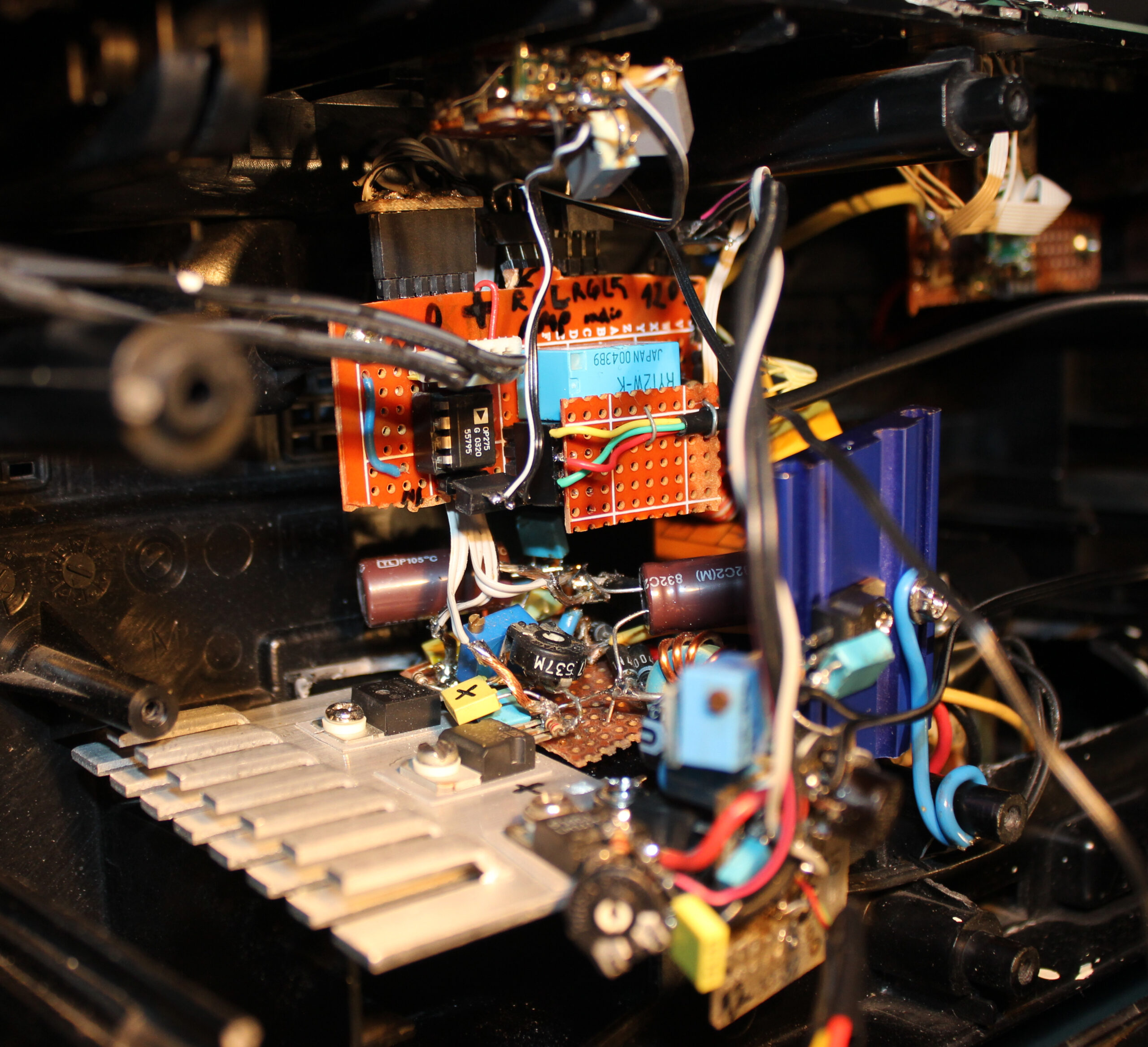
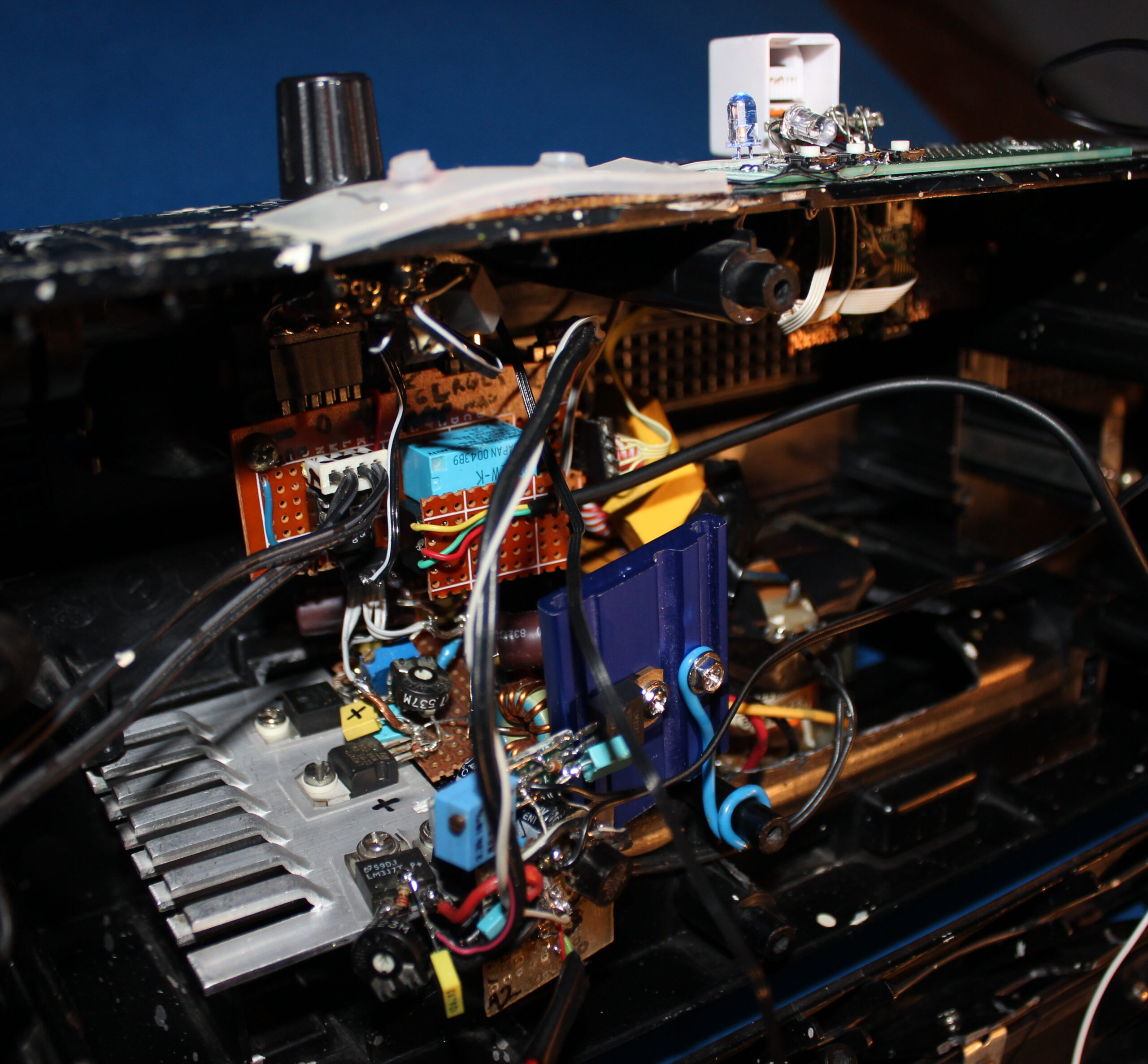
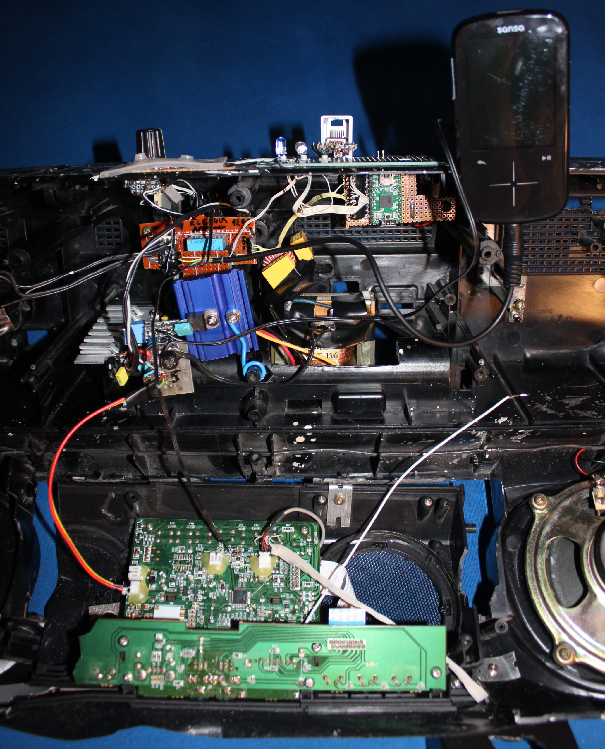
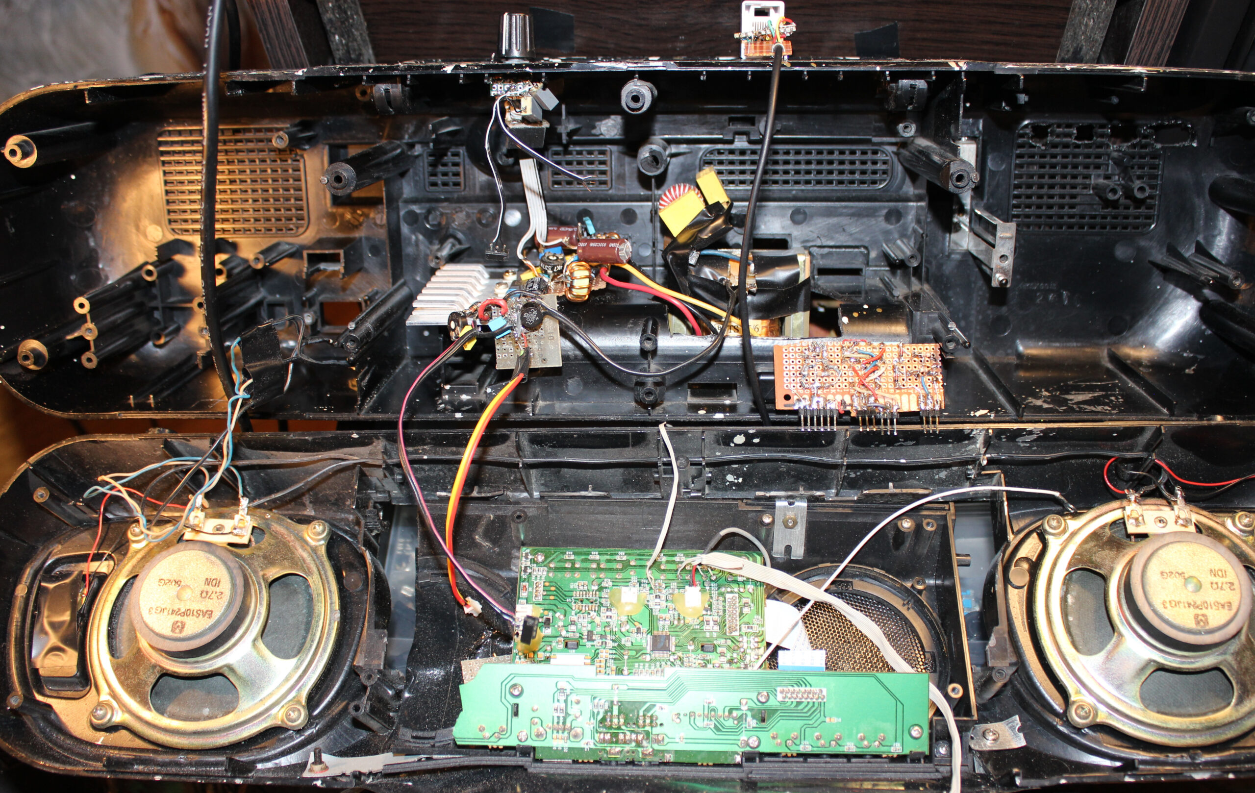
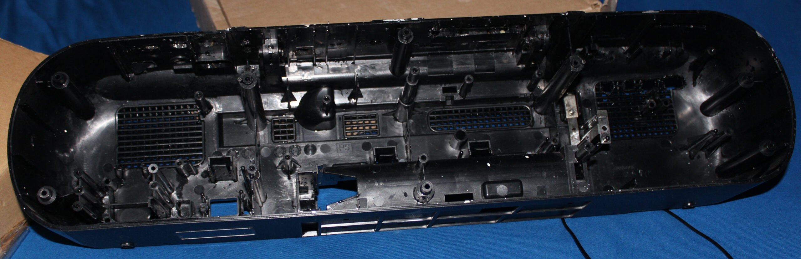
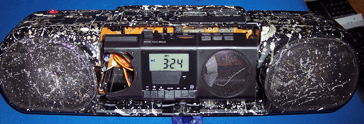
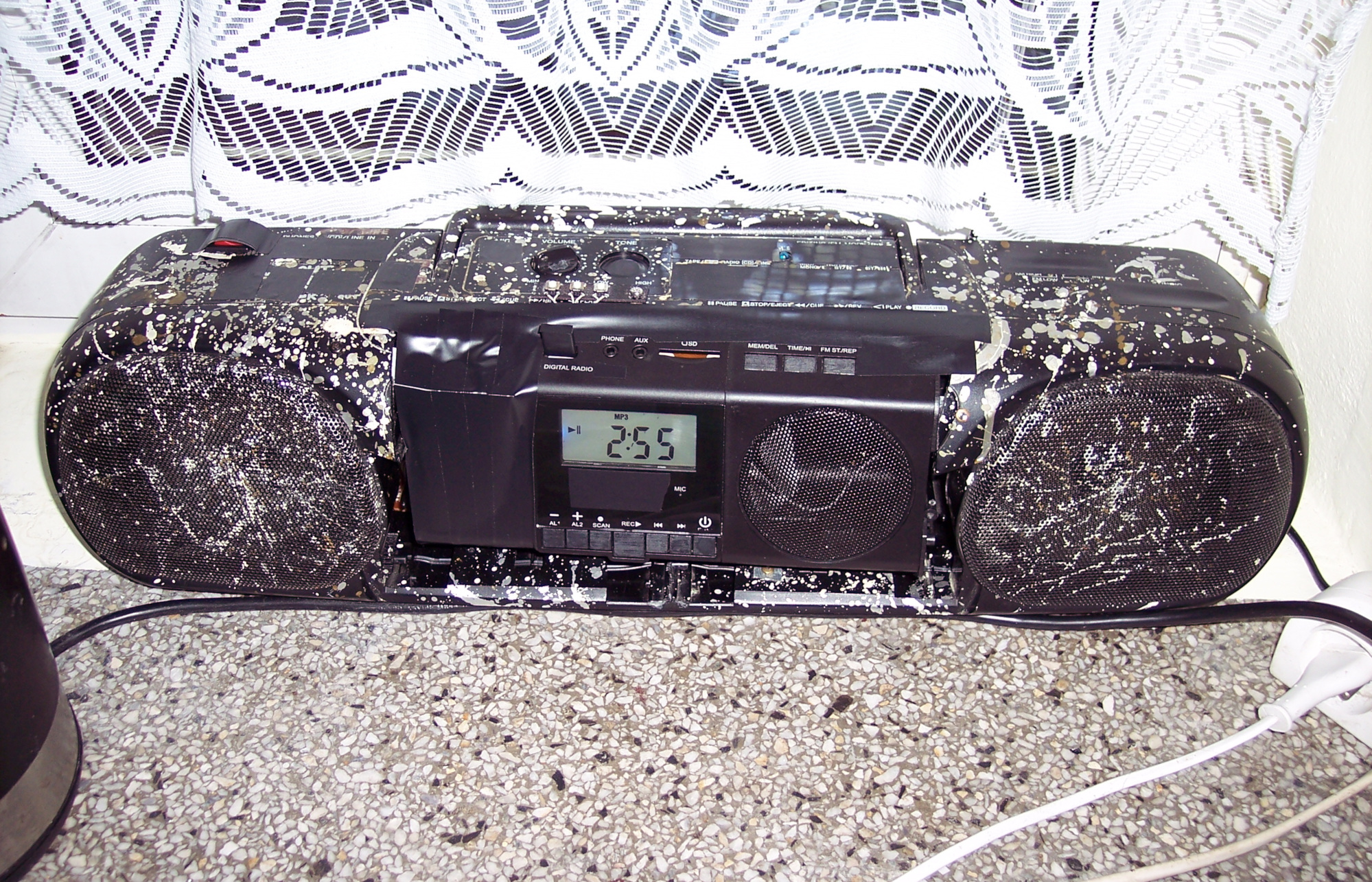
This is a continuation of (a long and probably boring, yet few times already coming back topic of) my modifications to an old HiFi. Which we use in kitchen, for showing clock (my weather station) and listening to music. Now I put both player and clock inside, between speakers. I also got rid of my old power supply and made it use less power and lighter too.
📜History
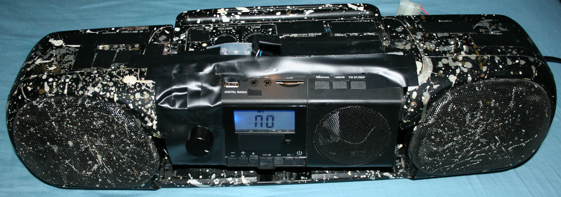
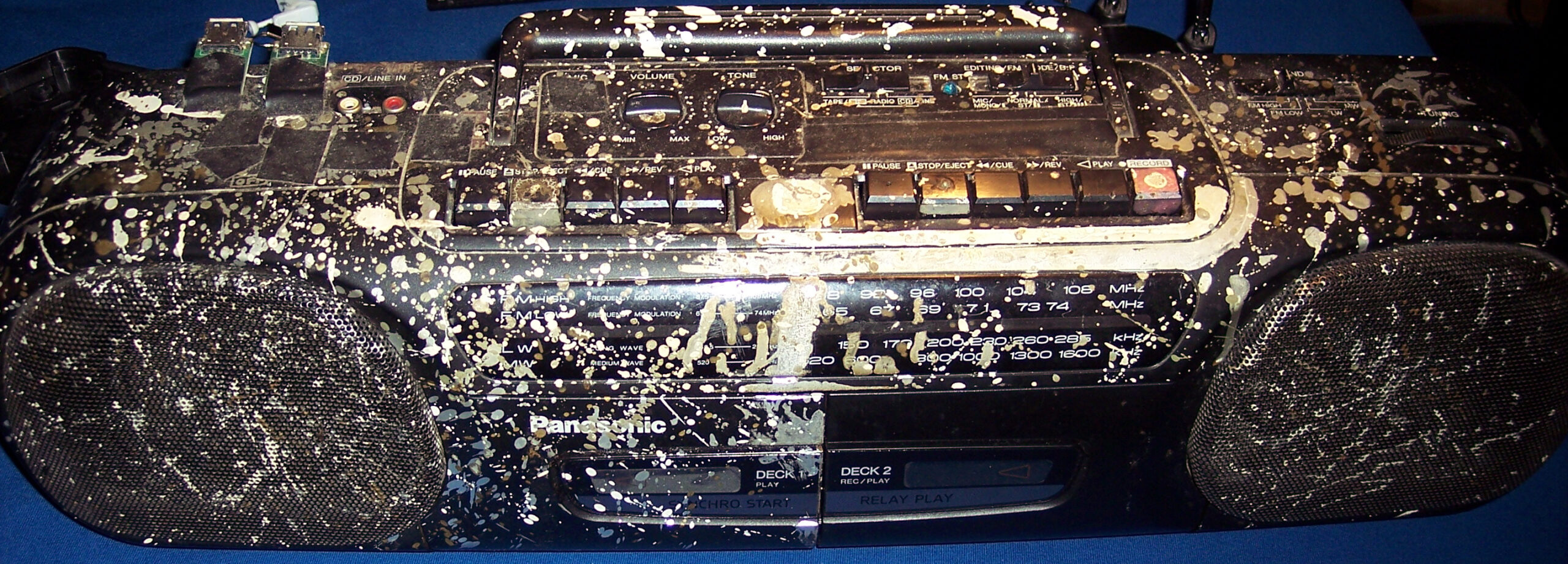
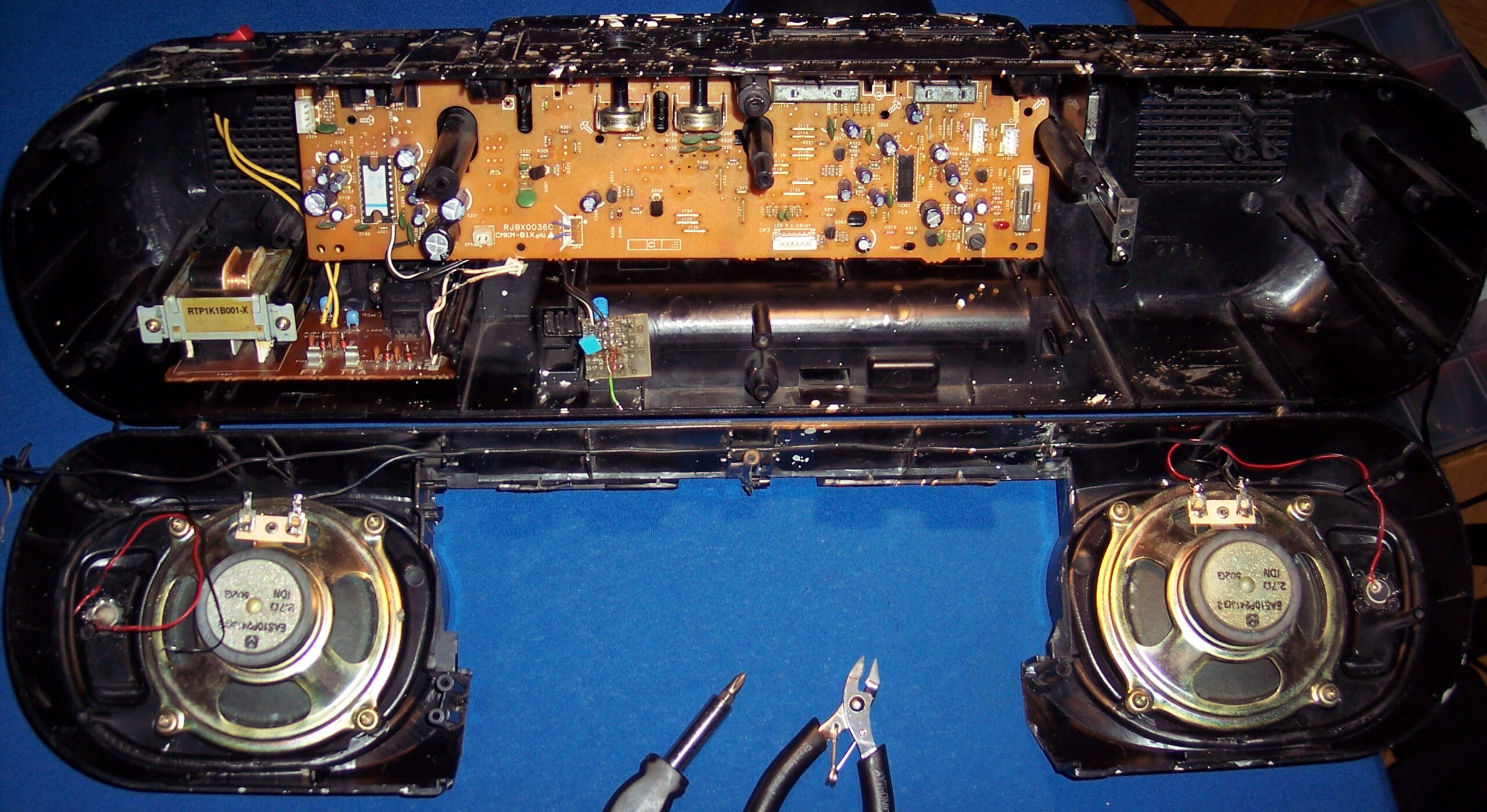
It all started a very long time ago in 1997, in a different age when cassettes📼 were roaming the Earth🦒. Back then I got this Panasonic RX-FT530 Dual Cassette Player/Recorder (original pictures). Not long after I started modifying it with what I could, to suit my needs and make it more usable (e.g. LED lights, faster spooling etc).
This is covered in detail in first project. On that page still, I did a major thing in 2020, by throwing out not used cassette decks, and mounting (or should I say butchering🪓) a digital radio (without its speakers) inside here, just between this HiFi’s speakers. Then connecting it and making a nice source switch between radio and player, using MCU and relays, with buttons and LEDs. Also added another source later from my PC, through ceiling and long cable.
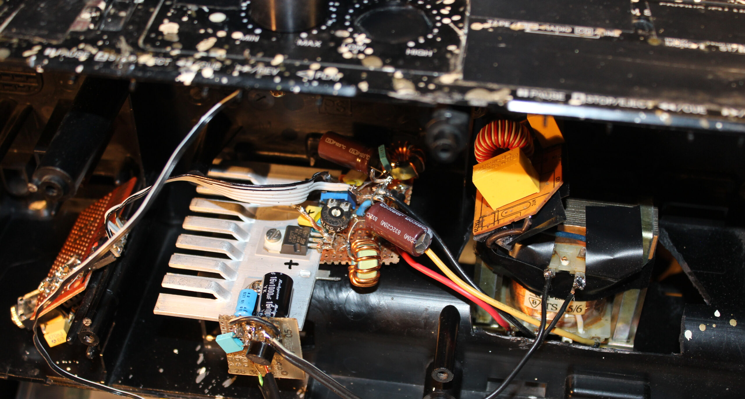
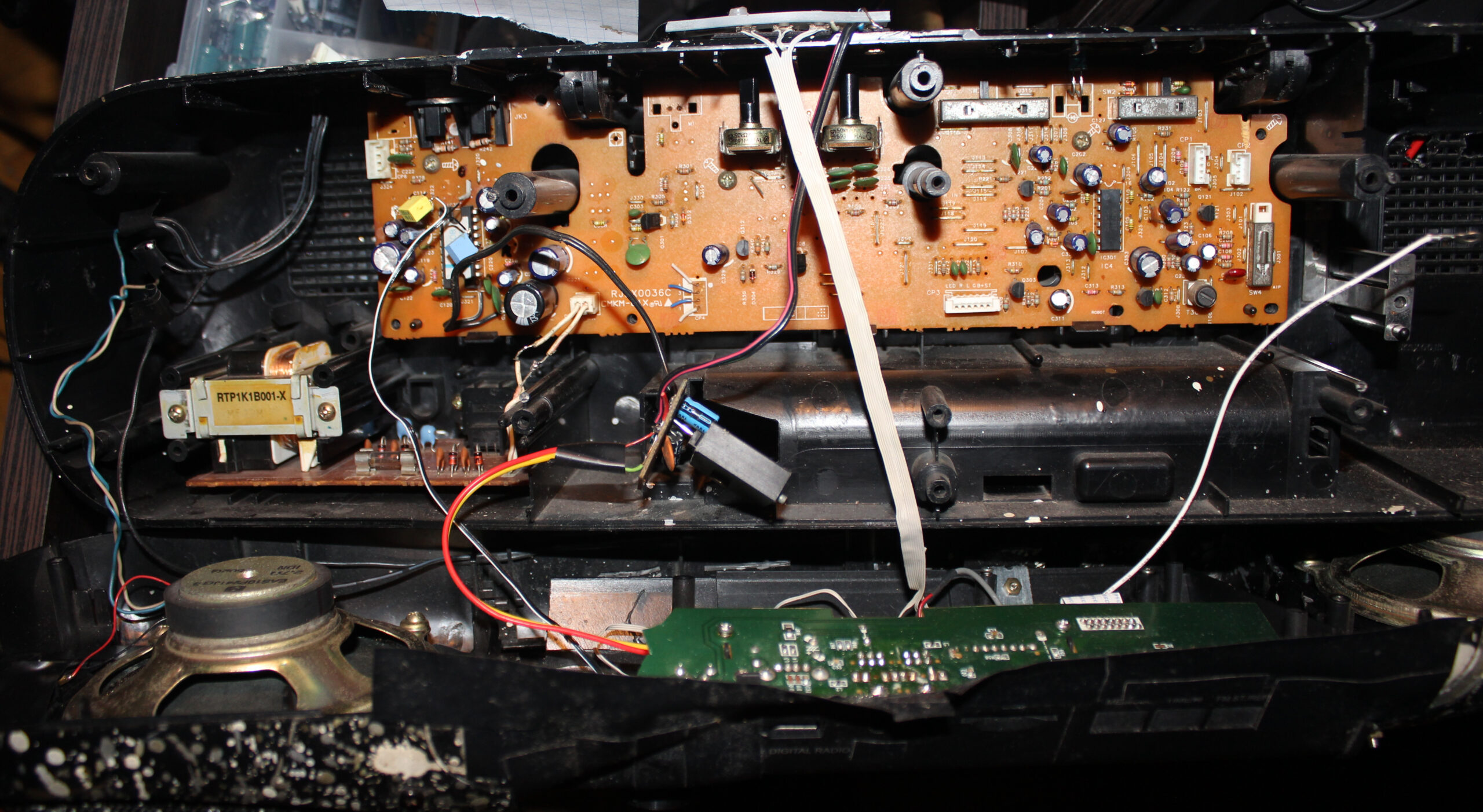
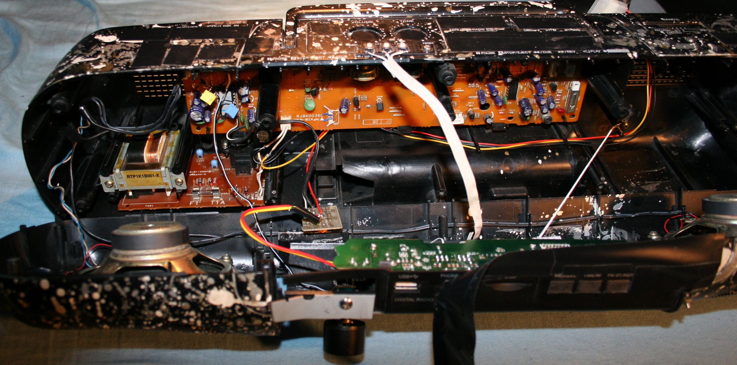
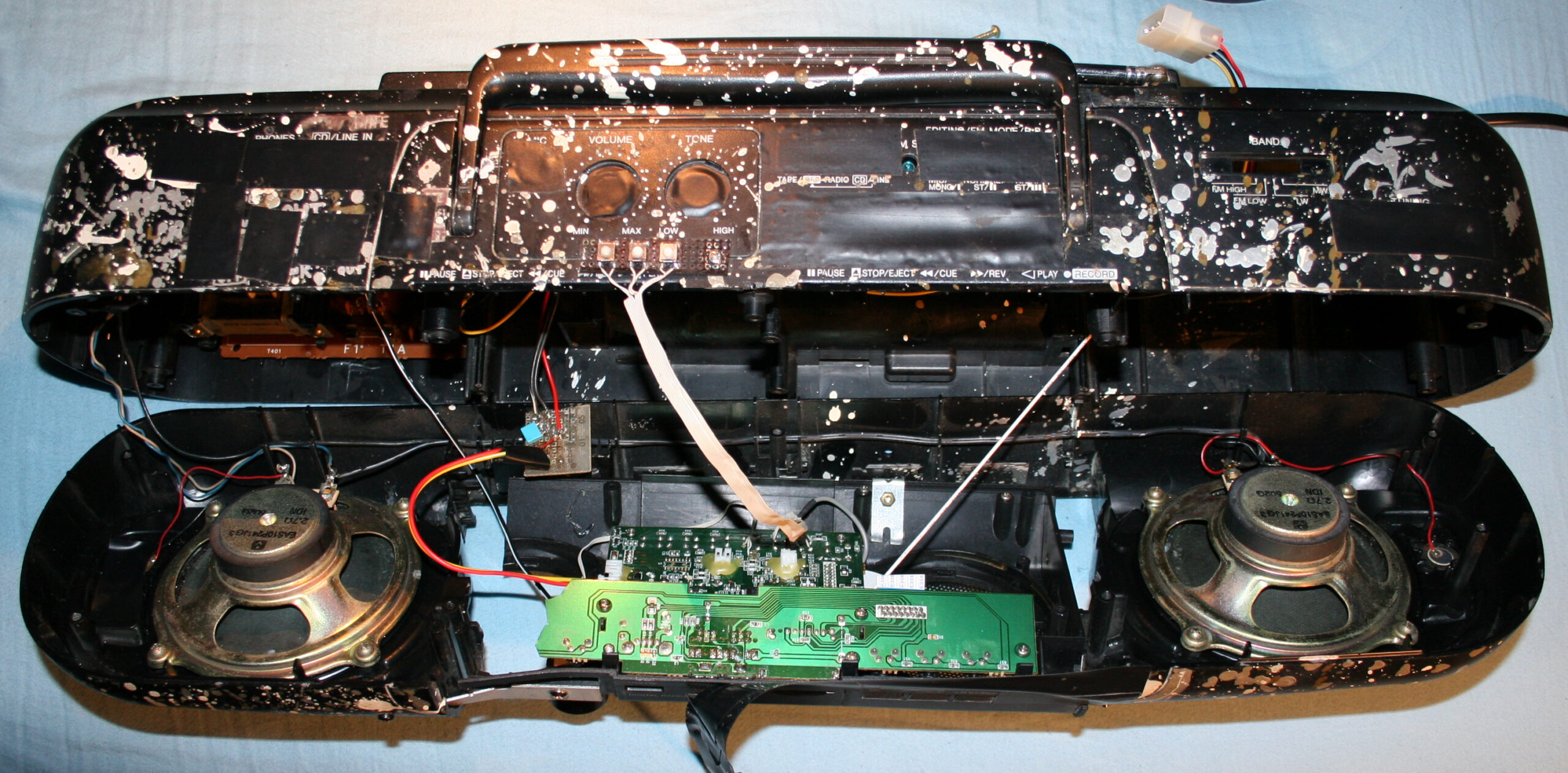
Later in 2023 second project I got rid of all original PCBs, amplifier and power supply. I made my own (still from a transformer) with 2 voltages and +-16 V voltage regulators. Back then I still was convinced that’s the way (OP275 op amp pdf says it makes less noise so). And it was how I did it earlier too in my guitar distortion effect. Unfortunately these regulators give heat and waste too much power. So it was going to be an issue for me later.
✍️Motivation
For a while this digital radio was okay and used. I recently bought a tiny TEA5767 FM Radio Module (e.g. here). So the radio could likely be just that small. And could replace the whole digital radio here. Which isn’t really used today by us now.
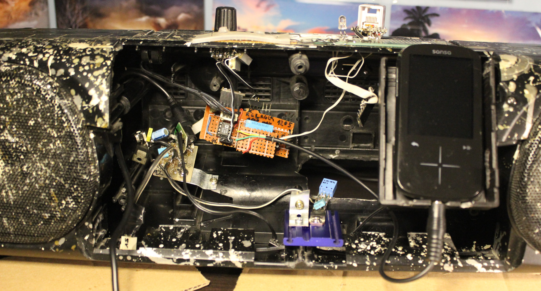
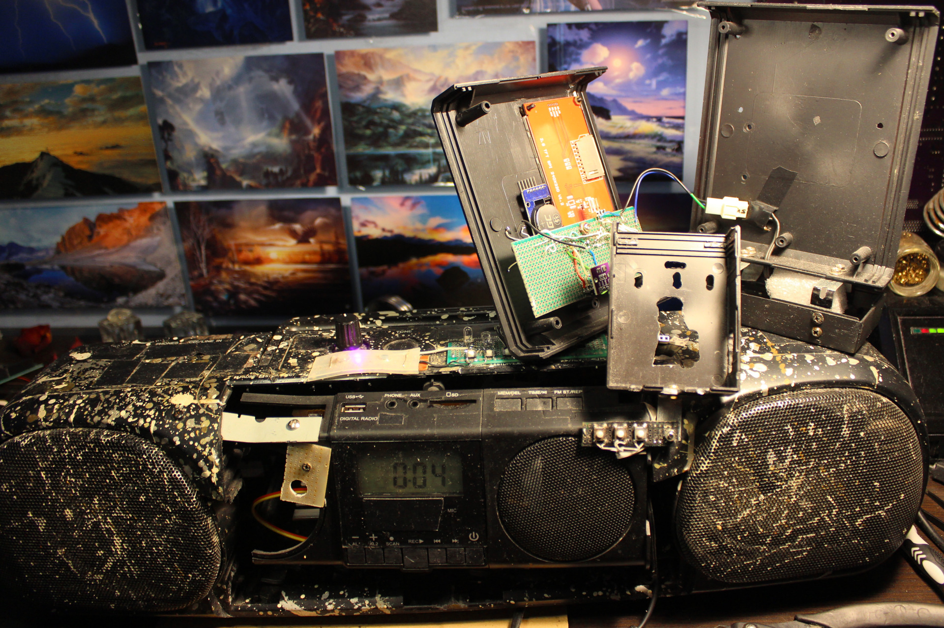
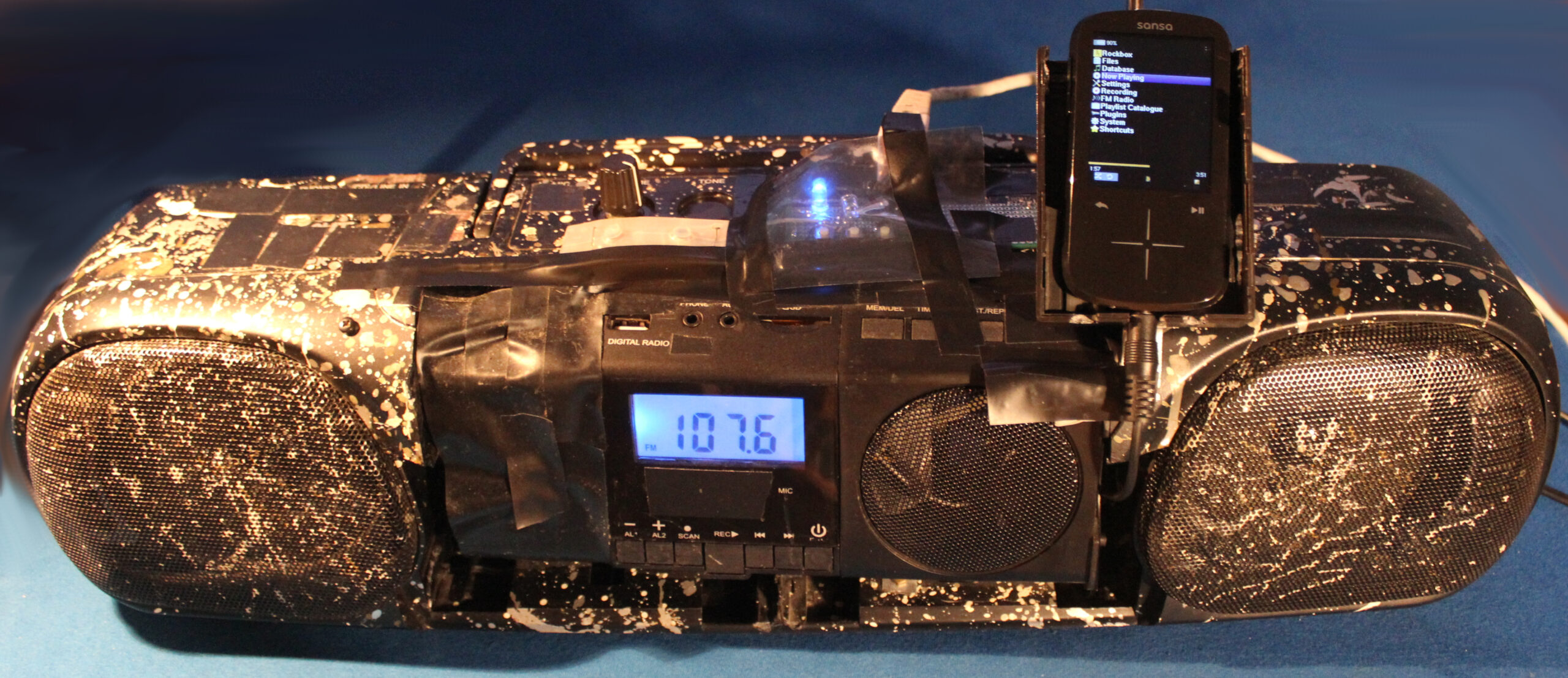
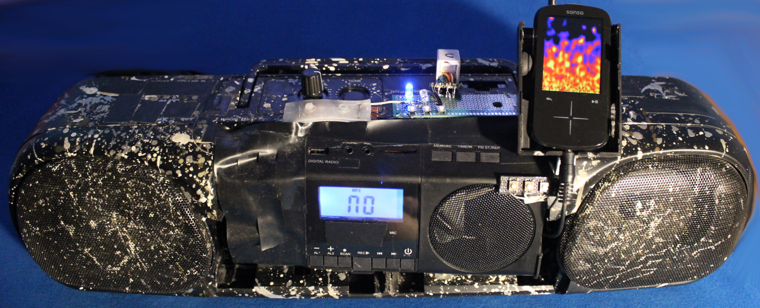
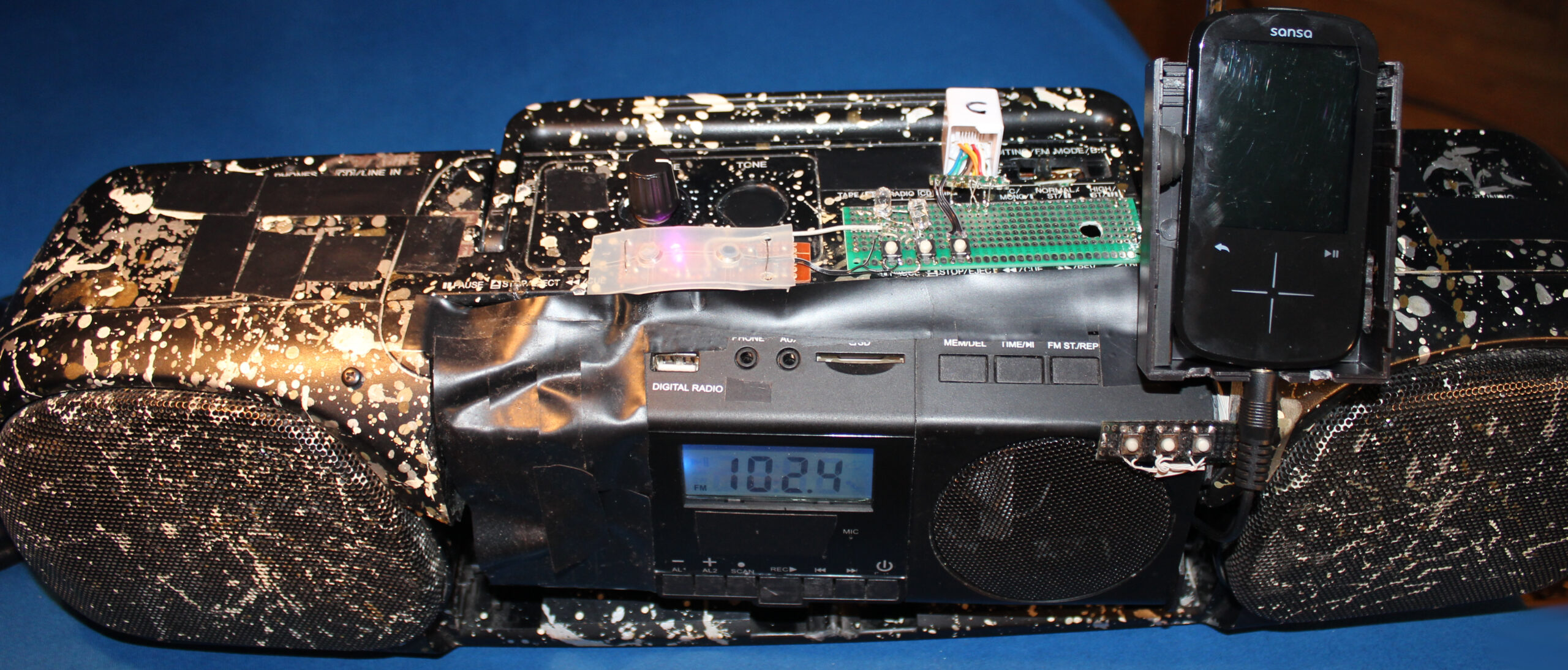
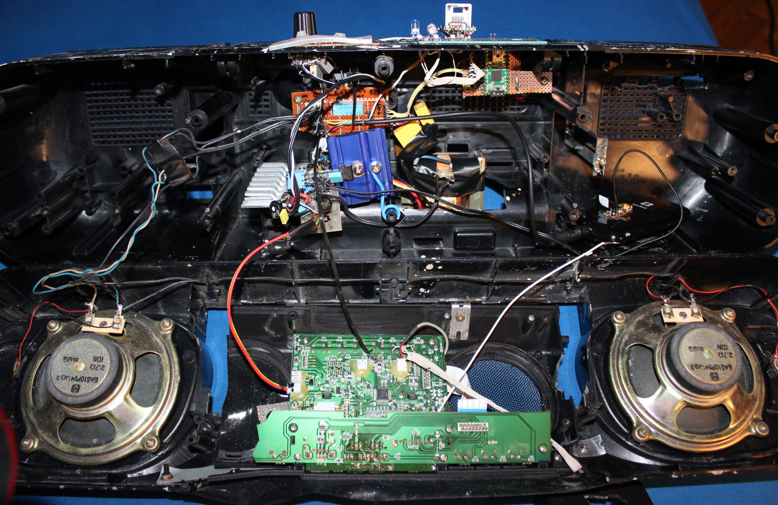
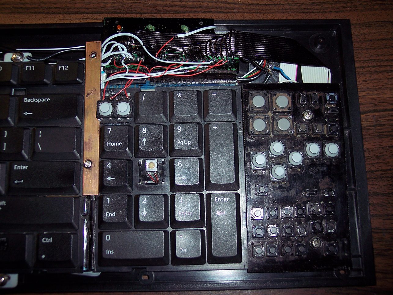
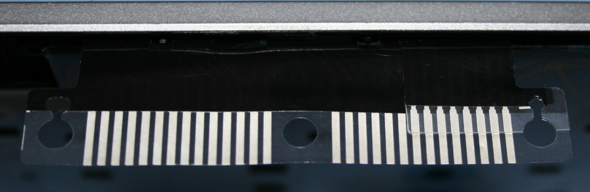
There was no space for my music player (Sansa Fuze+ with RockBox), so I mounted in on this HiFi. Later when I made the weather station, I also mounted it on this HiFi. The picture here, shows both. Sure it was usable and needed, but it doesn’t look great, rather crowded and separated.
Another reason was the high power use of this HiFi (about 3 to 5W), due to my old transformer based power supply with too many voltage regulators.
Both finally made me rework this thing once again.
📊Features
For now I got rid of the radio. It’s a further thing to do. Possibly not needed at all. I also got rid of that MCU and source switch. It’s only the music player here.
It now uses an impulse 12V power supply, which is not even inside, but near power outlet, like so many devices nowadays.
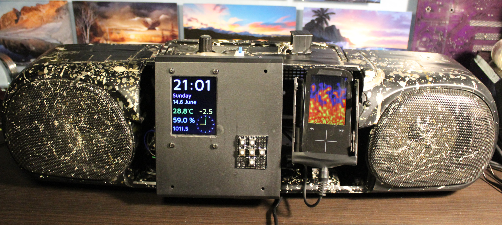
There rest stayed nearly the same,
⌛Conclusions
It does use less power. Now 2.4 W when playing not 5W. The audio amplifier section is only 0.3W (or less) now. Looks like my Esp32 clock needs 1.5W (way too much for me) and that player 0.9W or so.
It is lighter too. Weighs less mainly because there is no old, metal transformer anymore here for power supply.
It’s even smaller. Because those needed extensions from top of HiFi got moved inside.
It was done probably too quick, still it took 2 days to finish. As always there is a rush with this thing, as I need to listen to music in kitchen and not have this HiFi being under rework.
Another thing as always, it needs an extra step of cleaning. This thing (after years) always gathers dust. Since it has holes, it also gets inside, even natural stuff from outside as window gets opened during spring.
So I had to postpone the thing I actually wanted to do most since a while: using this clock’s ESP32 with display to also feature radio and audio player in one device. It’d be best to do it first on other ESP32 as it’d be slower to develop, while kitchen HiFi is used few times daily.
Well with this project as with my keyboards too it’s usually my history of learning how to do things and making few working (but not best) things along the way (years apart due to other projects). Looking back at those previous, even ridiculous versions I could say those were not needed or a waste of time. But that’s just how I learned that. Usually I need a working thing faster, not first spending a week on developing the best possible version.
Lastly it is nearing its 30 year anniversary, even if just case and speakers are left from its 1997 original. So it got a long life, instead of ending in garbage like so many such products, renewed and produced yearly or so.
📷Gallery
Just a few pictures. Much got removed, nothing new added.
This project is a PC mouse modification with very light press keys, using mini magnets.
📝Motivation
I have been using my keyboards with modified keys since 2004. They have been nice and a joy to use, less tiring too, since I cut off the rubber domes to reduce force. Still there are limits from the foil beneath. They are better also from medical reasons, less force means: less fatigue, less likely injuries, etc. It’d be good if the freaking old industry didn’t sell old crap for 50 years. As with keyboards now just with added RGB lights or even big display under, or small for for each key, etc. To maximize cost and profits and cash on the stupidity and looks instead of functionality, ergonomics, productivity. Yeah whatever, that’s why I do it myself (DIY).
Since years I’ve been using my latest keyboard (has a display and my own firmware) with Layer 2 having keys for mouse buttons, mouse move and mouse wheel with acceleration. It is much better to use (than those real from a mouse) because these are now light press keys (about 20 gram).
It’s been way too many years (over 30) of me using the default PC mouse with those ancient old microswitches. It’s just retarded for me nowadays. They usually need like 75 gram force (gf or cN) to press, have that old click sound. And the button under mouse wheel needs even more, like 100 gram. At least that’s what my previous (20 year old) mouse Logitech G5 has: OMRON D2FC-F-7N (10M) which says 0.74N (N to gram convert), cool websites with that switch here or here, video here, images.
▶️Video
Video here. Shows inside, weights testing, and at end blowing air to press.
🔍Details
Here I write (a lot) more detail of my approach for keys, with comments.
Keys
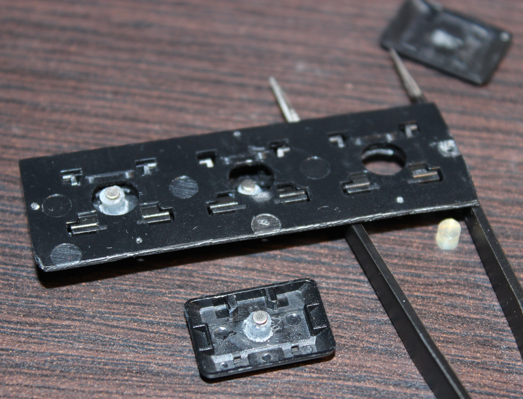
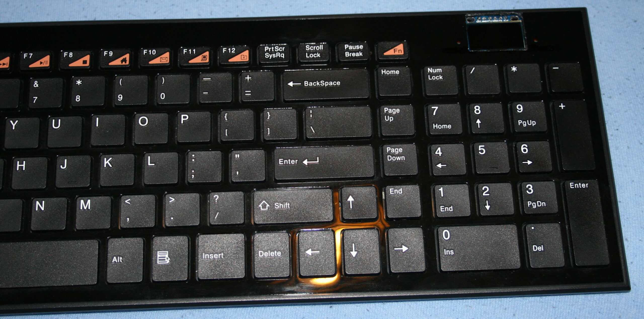
Keys are from keyboard (scissor switches), those narrow (like F12). But now for each key I use a Hall sensor (CS49E, SMD) and 2 tiny magnets. Thus so called mag-lev (levitation), since these magnets push each other out. There is no spring, no rubber just small magnetic force, making it much lighter and IMO say more reliable.
I saw earlier this page with video of another such way. And also there are a few keyboards already produced with such design. It’s just that they still have long travel and way too high press force, some still non linear press too. Obviously a nope for me.
Result
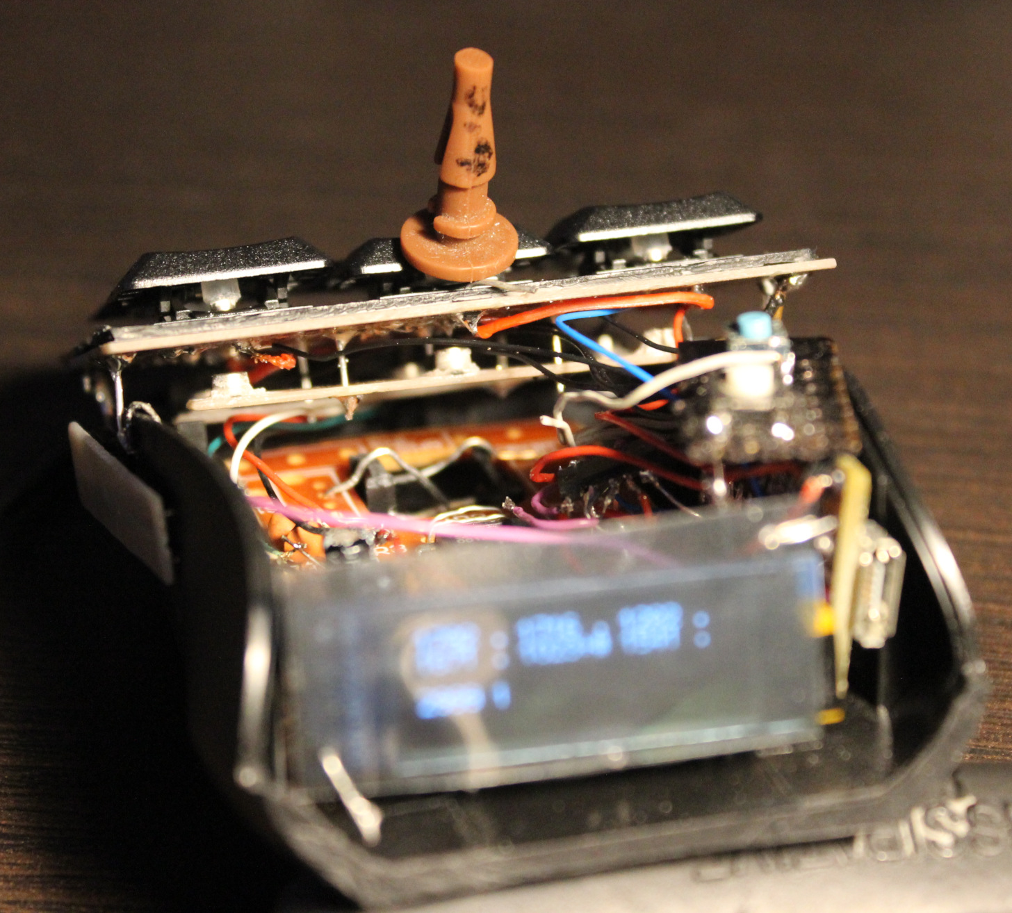
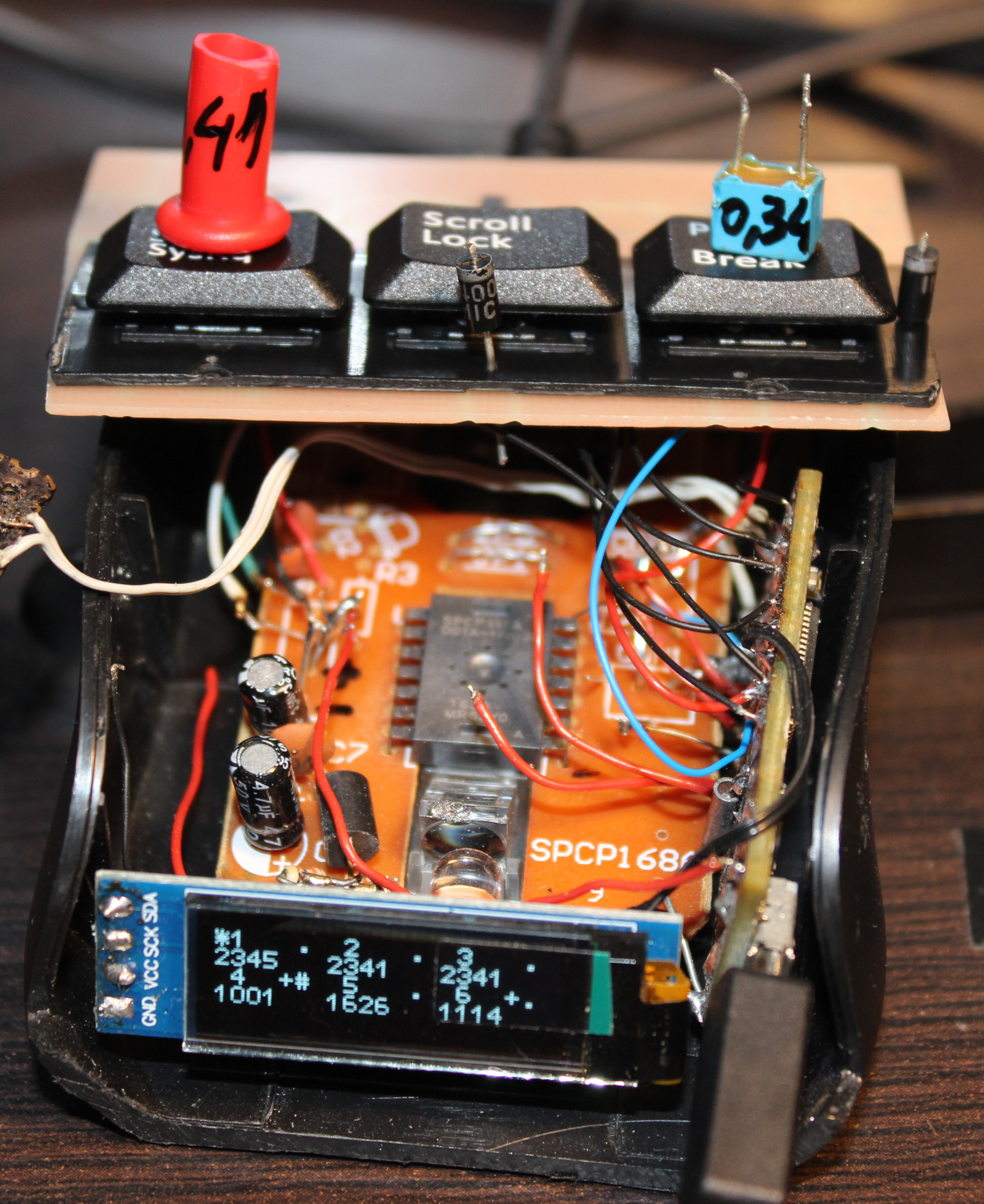
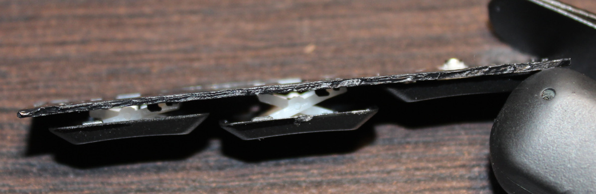
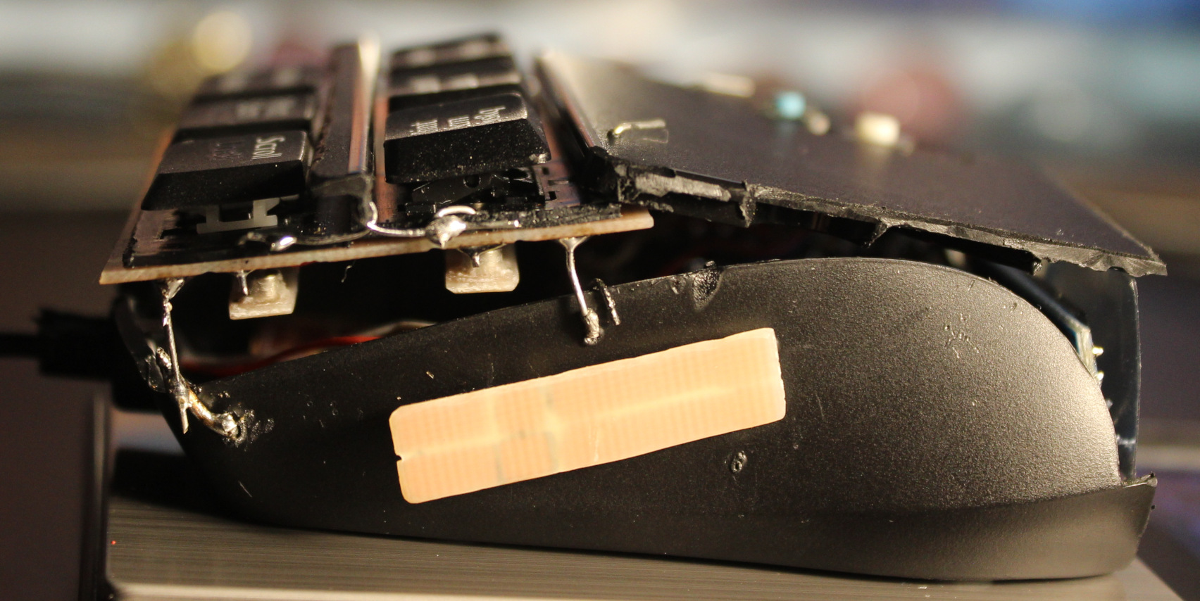
The resulting press force is way lower. I managed to get it even to 0.34 gram. It’s incredibly low, you can just put a tiny M3 screw on key to press. Or even blowing air to press works🌬️. I set it later to around 0.7 or 1 gram force. Of course this creates another problem, that you can’t rest your fingers on keys now. That’s why I put this plastic bar between keys for fingers to rest.
Silicone cylinder🛢️
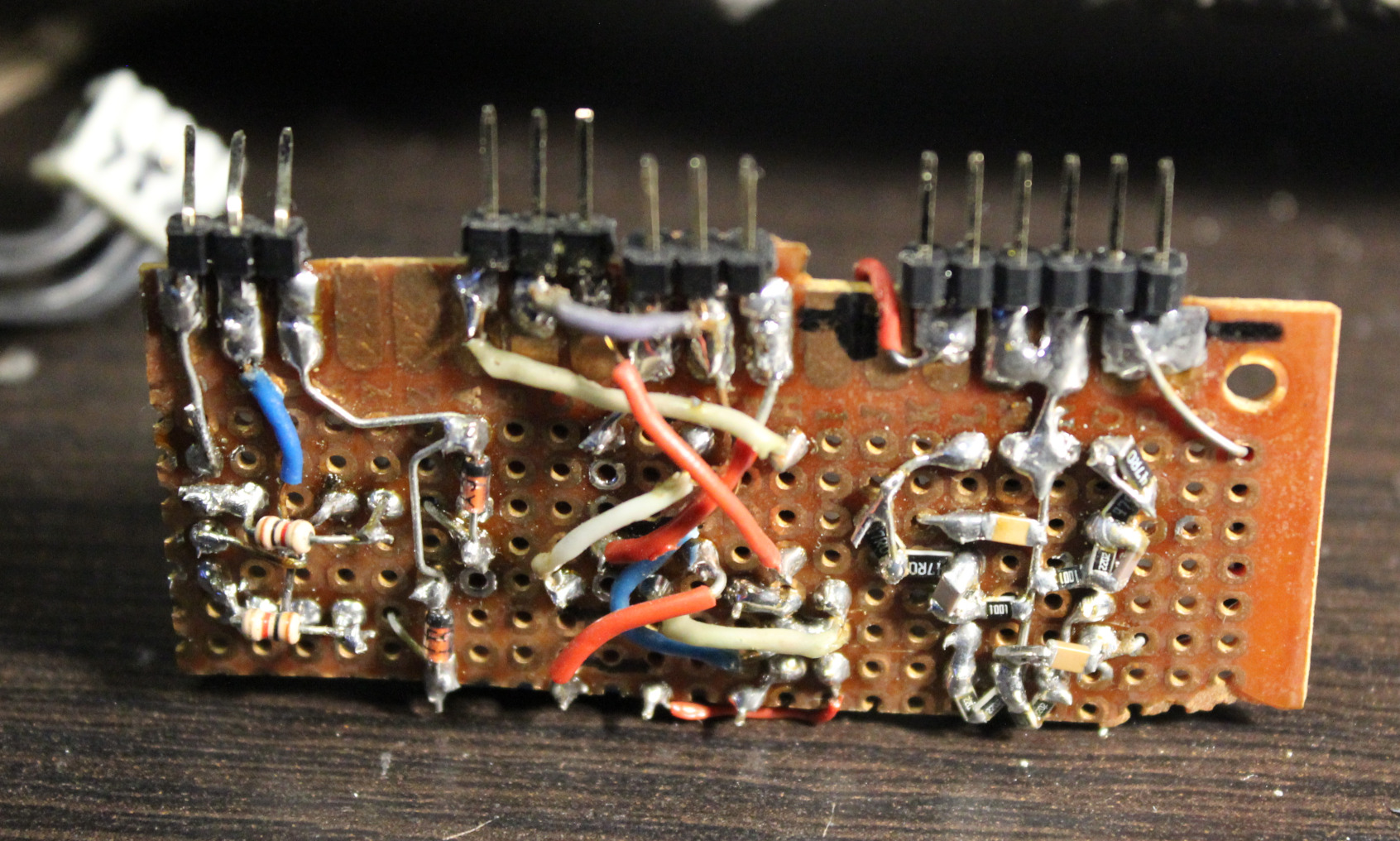
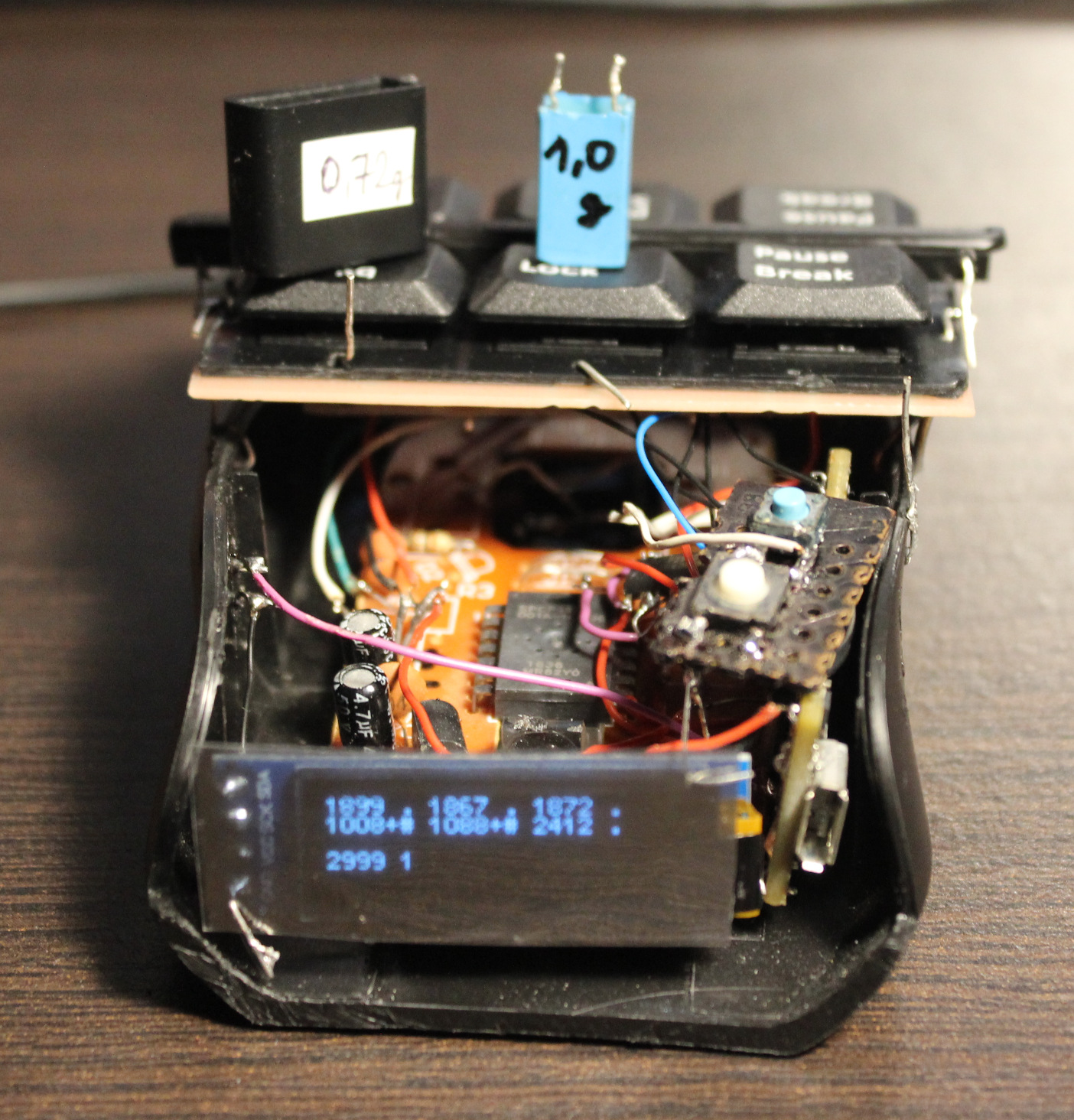
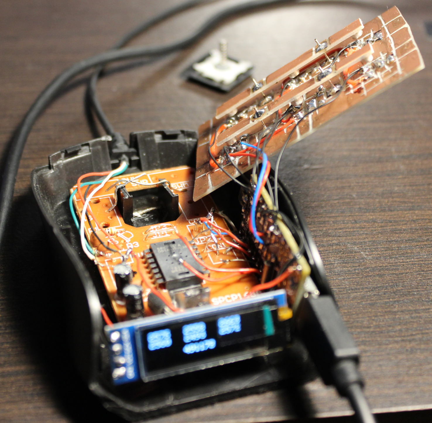
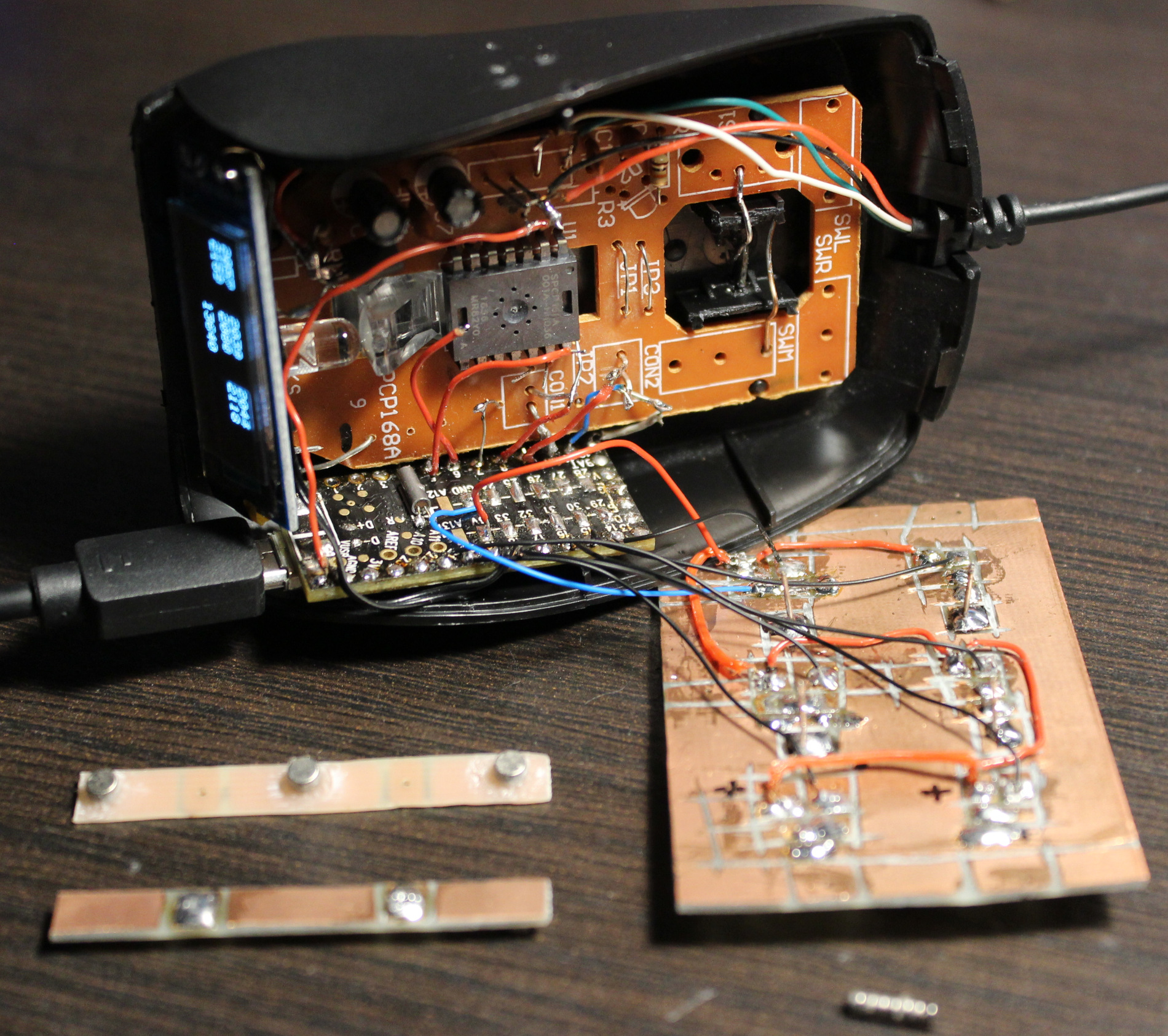
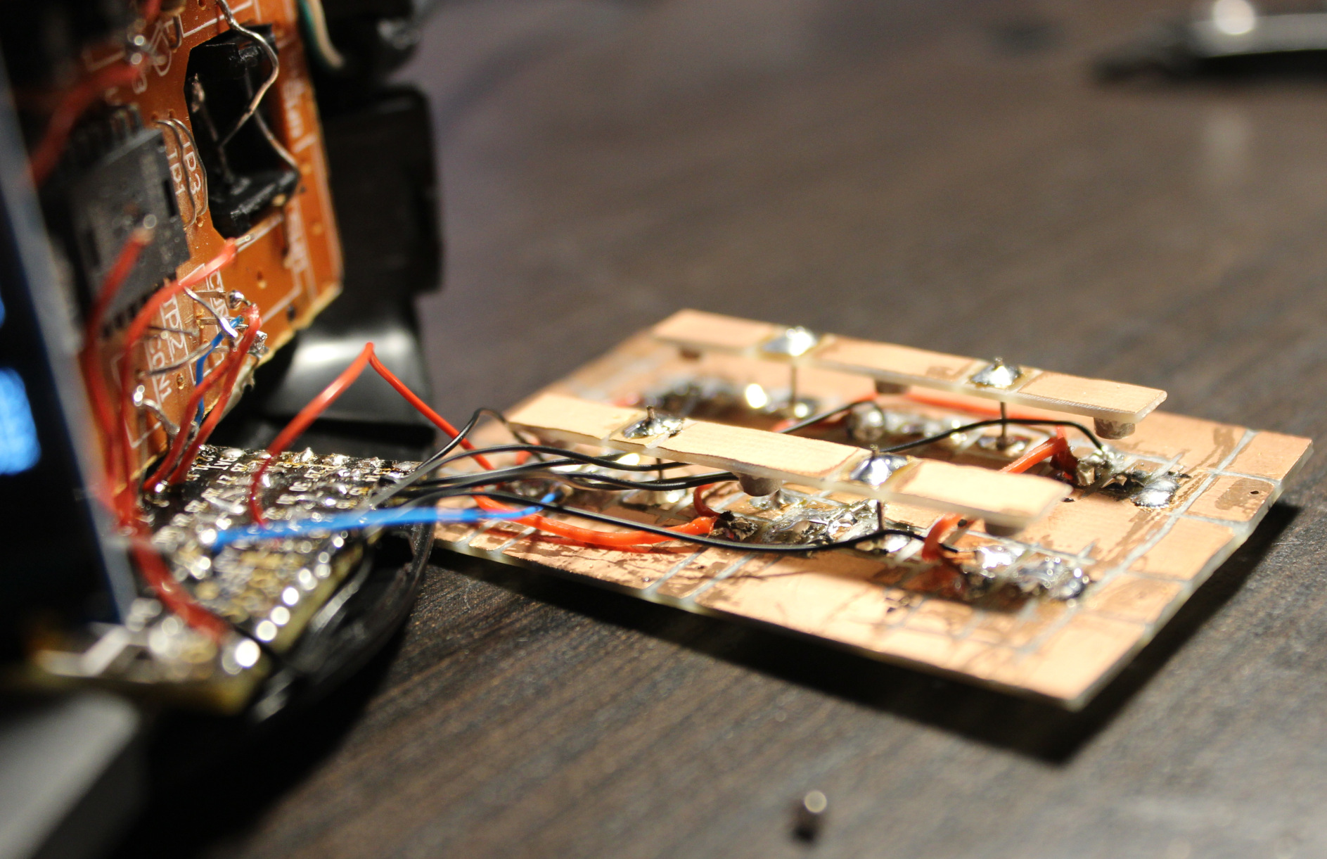
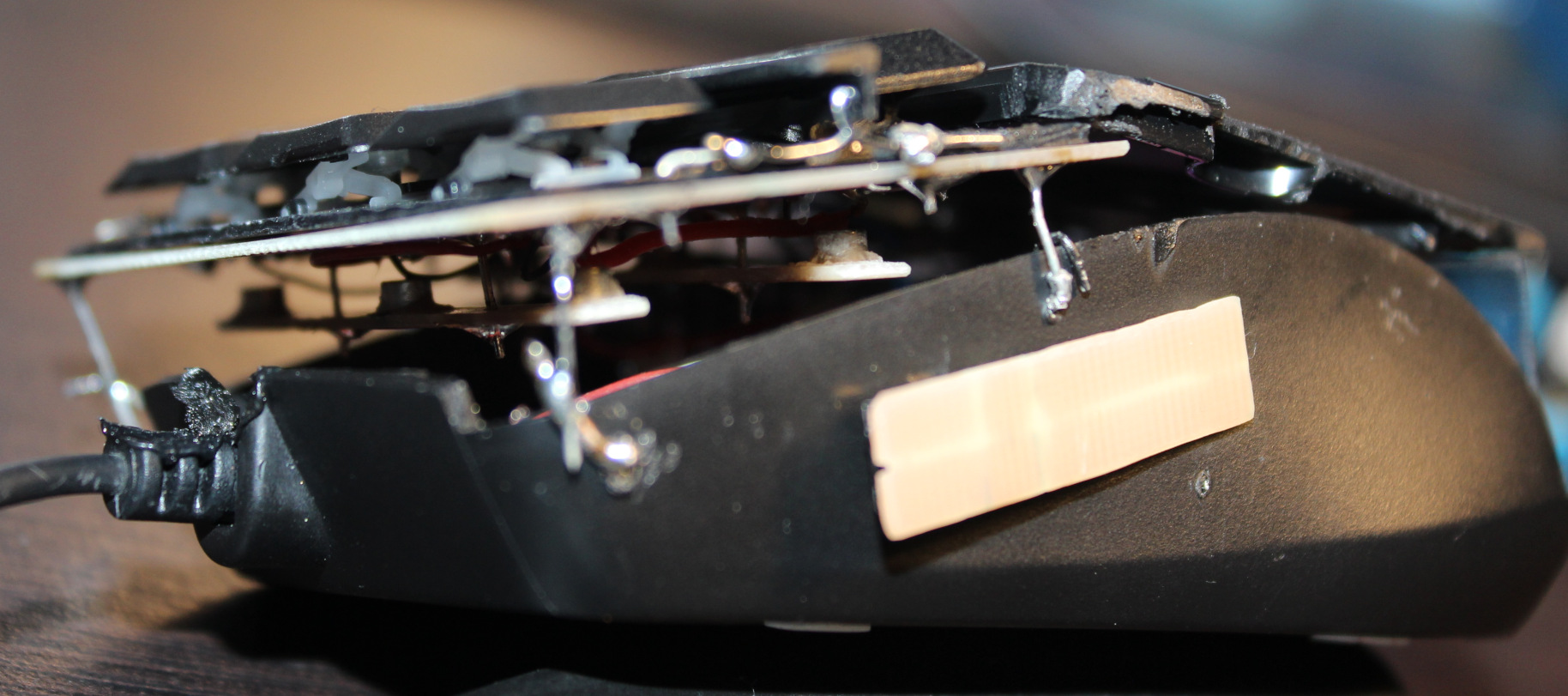
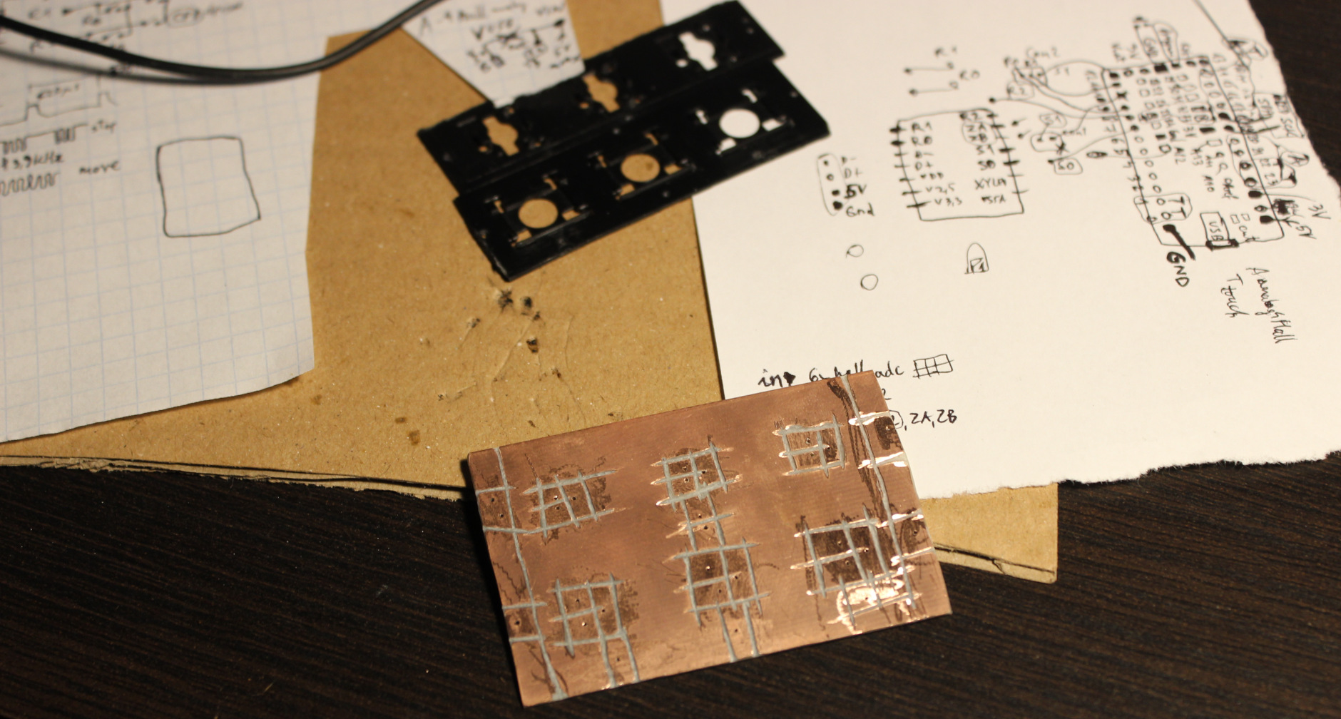
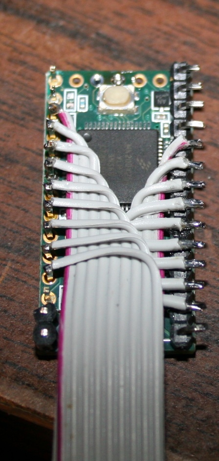
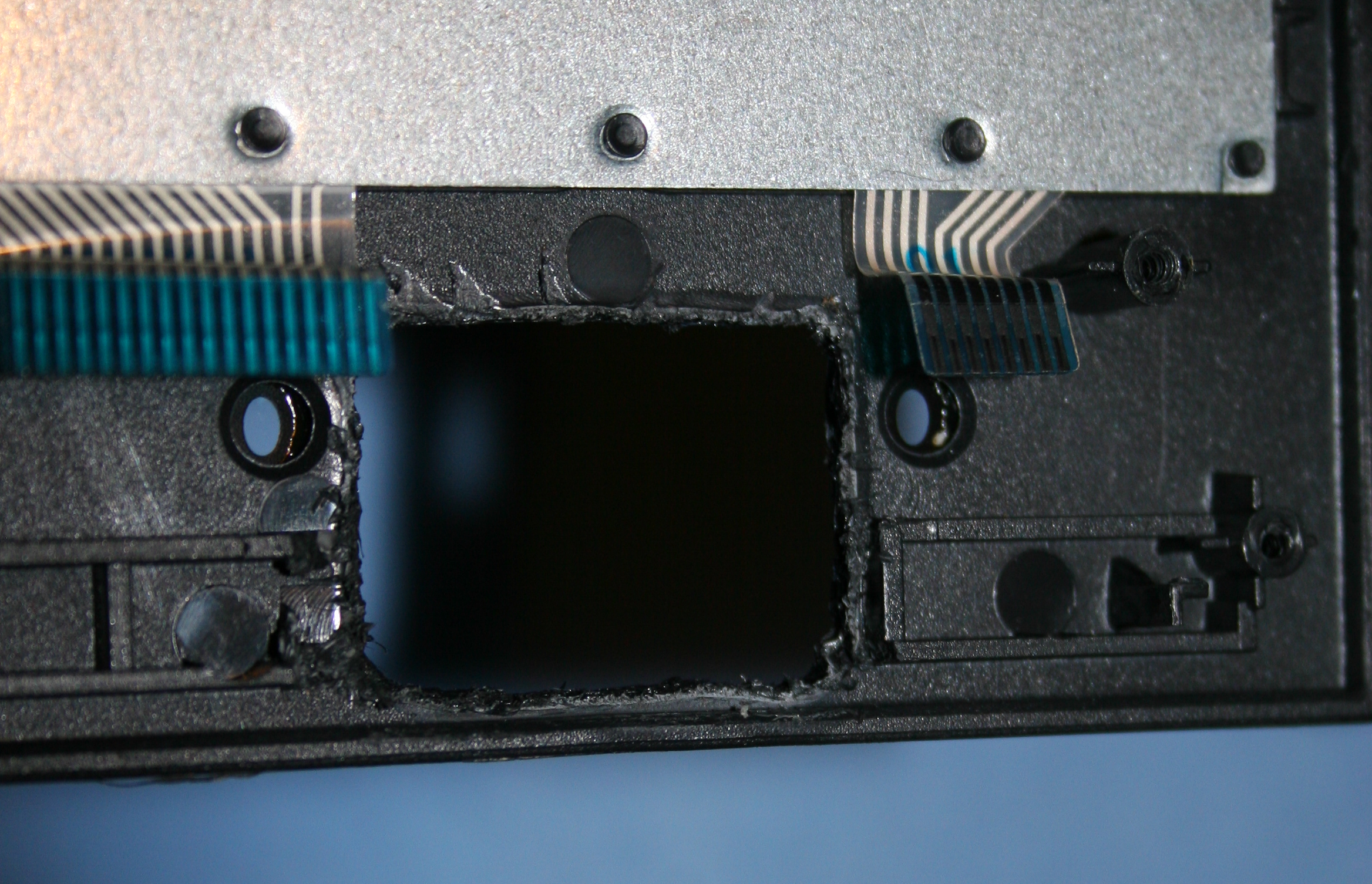
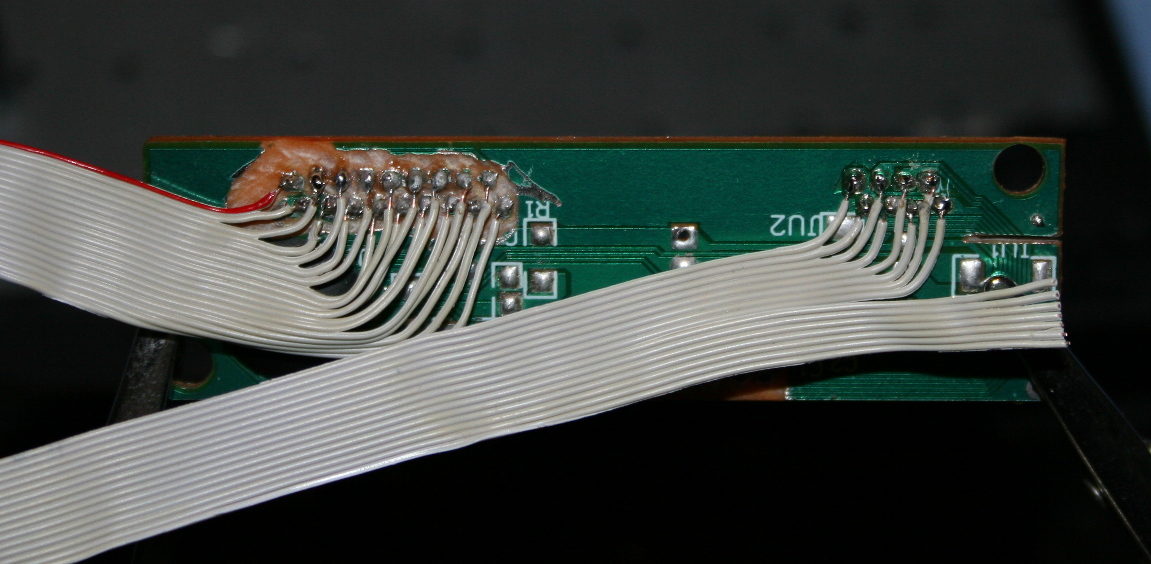
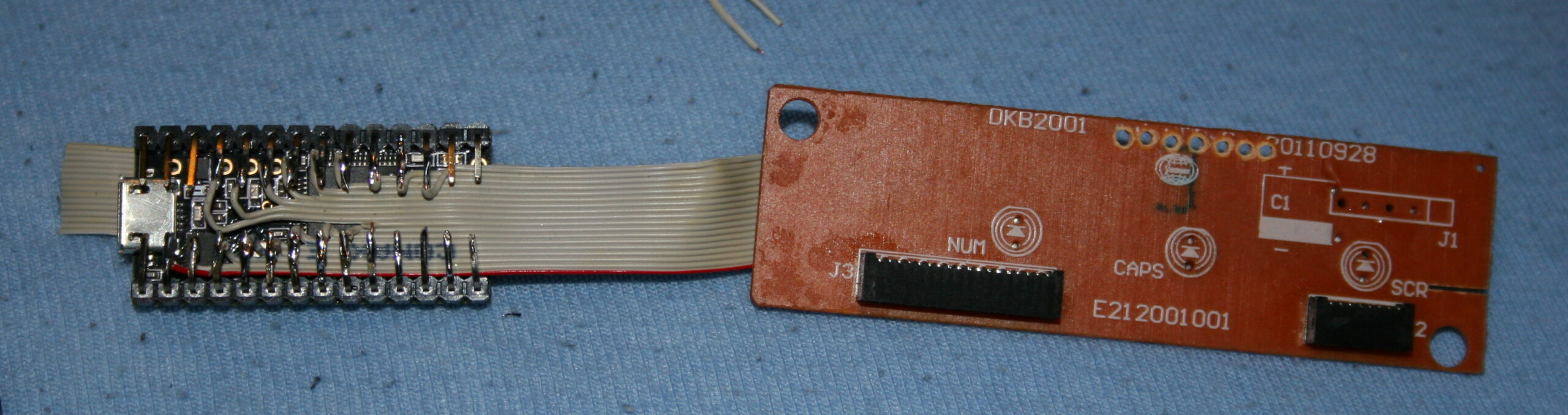
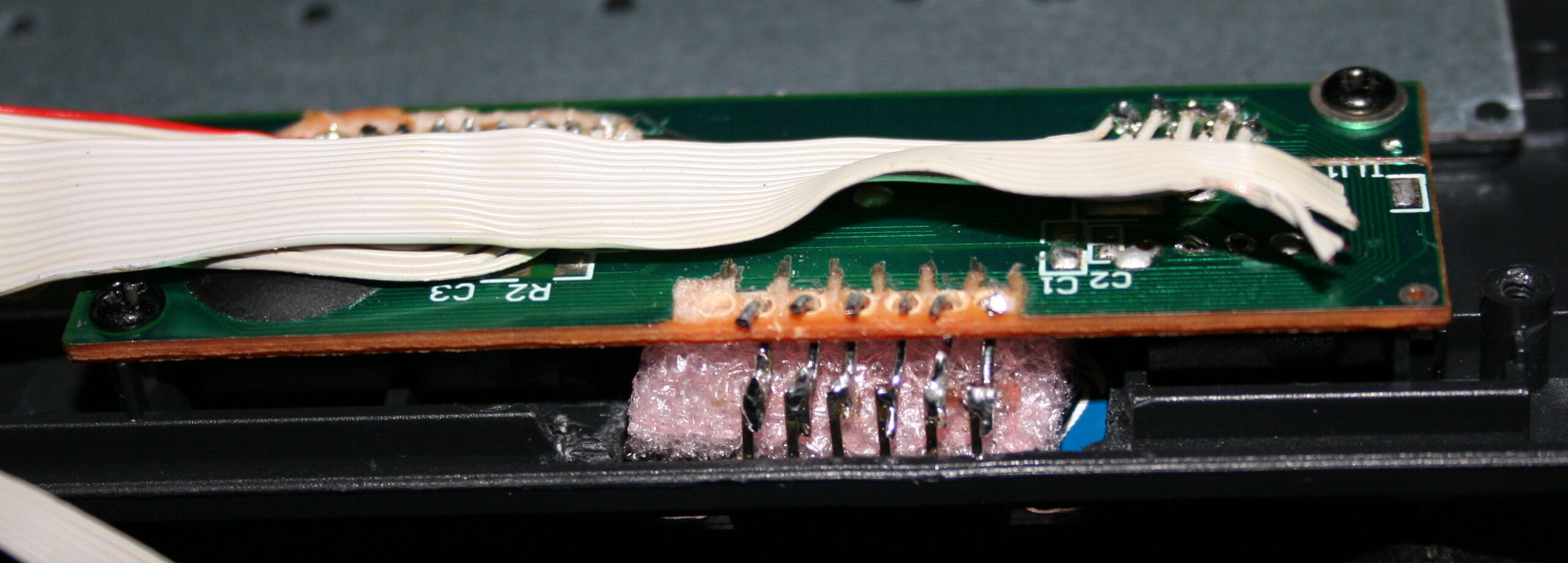
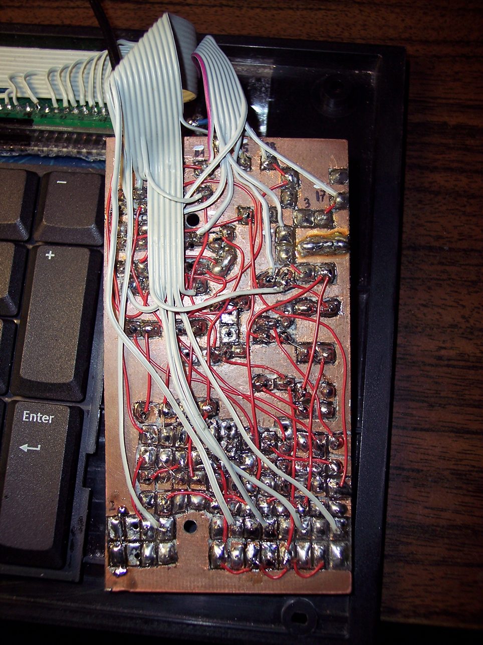
The top of key has beneath a (super) glued silicone pad (3mm diameter cylinder (I bought silicone rope and cut it), *height about 2.5 to 3.1 mm). Then on top of it glued the first mini magnet 2×1 mm (diameter x height). I think the default N42 neodymium🧲. This magnet when pressed touches the CS49E SMD Hall sensor which is on PCB. It could be a 2 layer PCB, but since I got 1 layer, this SMD chip is glued onto it, in right place (middle of plastic circle hole), then through drilled holes, tiny wires are soldered to sensor chip’s 3 leads.
Travel
Travel distance can be changed, but needs cutting *height of that cylinder and glueing magnet again. Or just scraping cylinder and doing a new one with other height. It’s not that precise even if measured, there can be some tolerances in scissor keys etc. So getting exactly 0.5 or 1 mm travel would be hard. It is also possible to add just small tape pad⚫ (from e.g. black isolation tape) for a thin layer on top of sensor. It would decrease travel and also sound less when hit with magnet (2×1) from key. Less sound is also the reason why cylinder is from silicone.
Sensitivity👈
Also the less travel the less sensitivity and value change from Hall sensor. So MCU’s ADC is 12 bit, meaning it could get values from 0 to 4095. But it won’t since CS49E has 3.3V supply and its output has limits, doesn’t go below 1V or higher than 3.3V – 1V. Doesn’t really matter.
So I get about 1000 when pressed (magnet closest) and about 1500 for lightest (0.35 g) setup if done right. But it can be tricky if there is friction in scissor key, I had to slightly cut off a bit. If I didn’t do it you can get 1100 or so, sometimes if key gets stuck (while otherwise it’d go much higher) and that’s a problem (it’s unusable).
As for the regular keys there is no issue: 1742 for 0.72 g, 2146 for 1 g, 2416 for 2.23 g. This is plenty difference from about 1000. Each keys/sensor will have some minor difference too. Not required but could be set up with some calibration for each key in practice.
Magnets🧲
The two magnets distance affects mainly actuation force and sensitivity (max value). The closer they are the more force one needs to press and higher value if not pressed. There was a “interactive 2D magnetic field lines simulation applet” I used before to test best location of sensor and 2 pushing magnets (1 stronger), but I can’t find the website anymore (e.g. this).
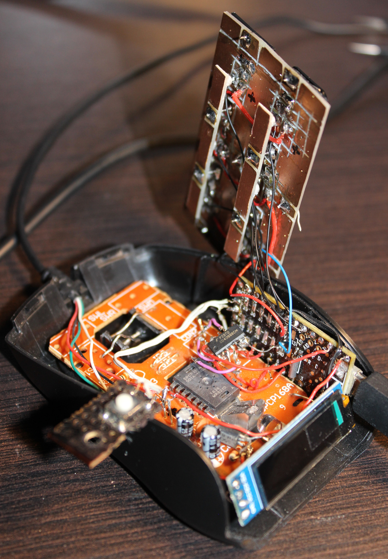
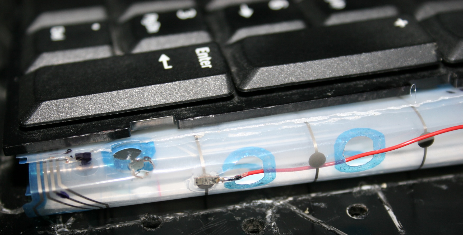
In general the first magnet (2×1 on key) needs to be closer to sensor, and get closest when pressed, and the second (3×2) should be far. This way I get most sensitivity. The second magnet when far should not affect the value from first (too much). It’s just there to levitate the key after all.
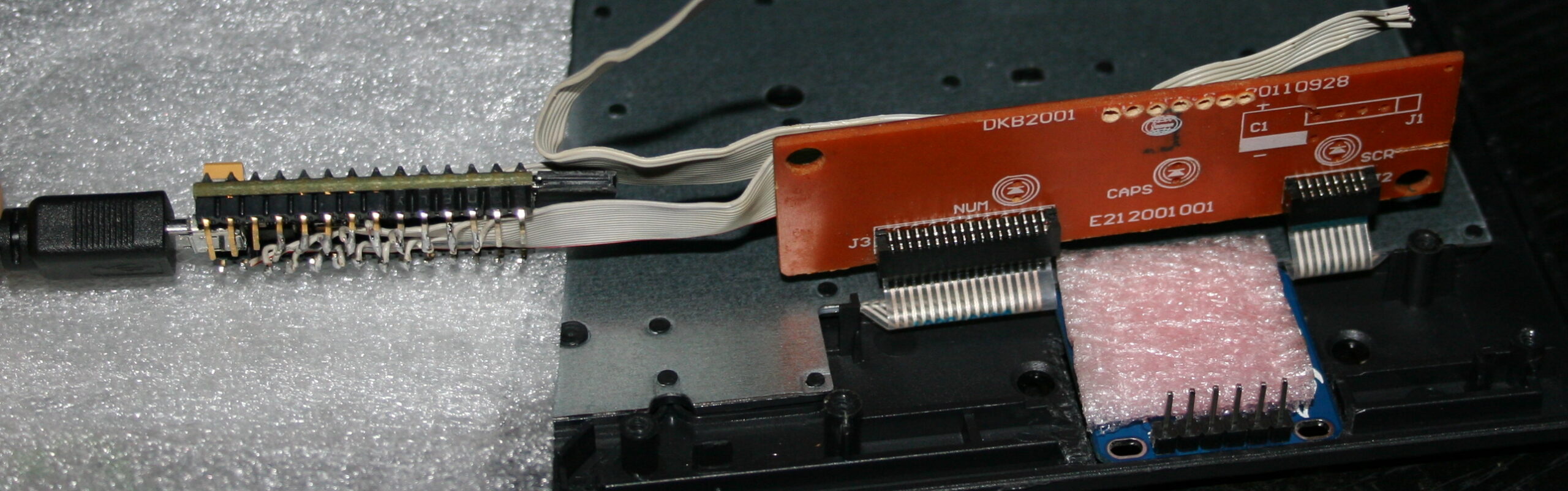
I glued second magnet (in row for 3 keys) to a narrow PCB, which is held by solder and small wires, above the PCB with sensors. This way I can adjust distance of second magnets and so the force for keys. The key resting values (1742 for 0.72 g, 2146 for 1 g, 2416 for 2.23 g) are increasing, because I did shorter distance of narrow PCB on right (last key value) for Right mouse button and did longer distance (on left) and thus lighter press for the (most commonly used) Left mouse button (first key value).
Customizable🔩
As explained above, the actuation (pressing) force is customizable. Not too easy, but easier than travel. One way is resoldering that narrow board closer (more force) or further away (less).
It’s also possible other way, by adding more magnets (3×2) to the one already there. Makes magnetic push force stronger and so needed actuation force higher. It’s a worse idea since magnets aren’t cheap and one is enough. But it’s surely easier and quicker to adjust this way. So more user friendly.
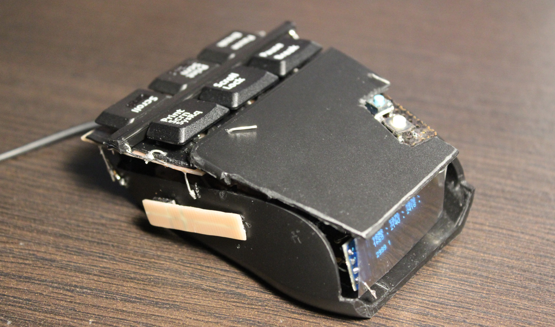
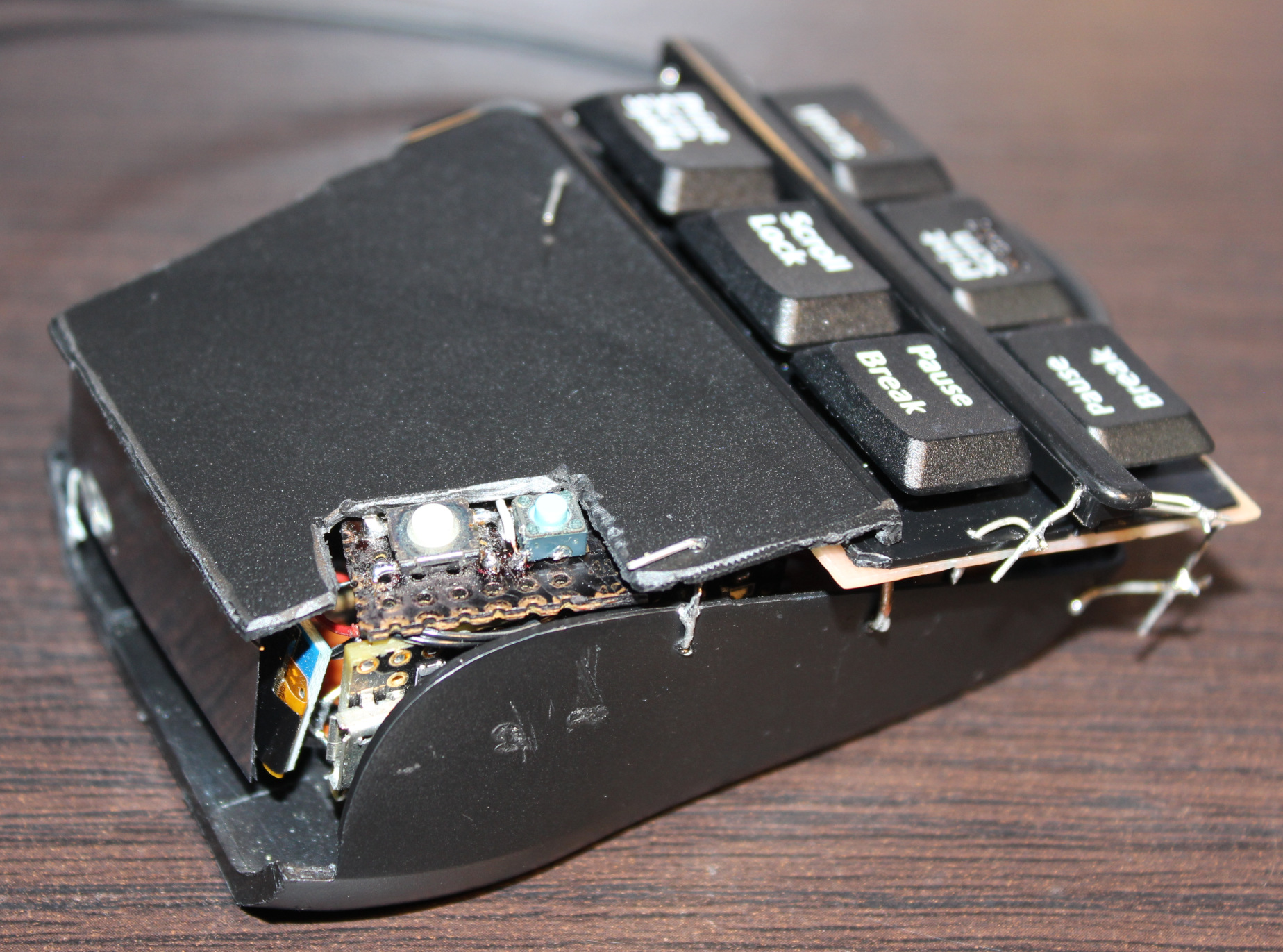
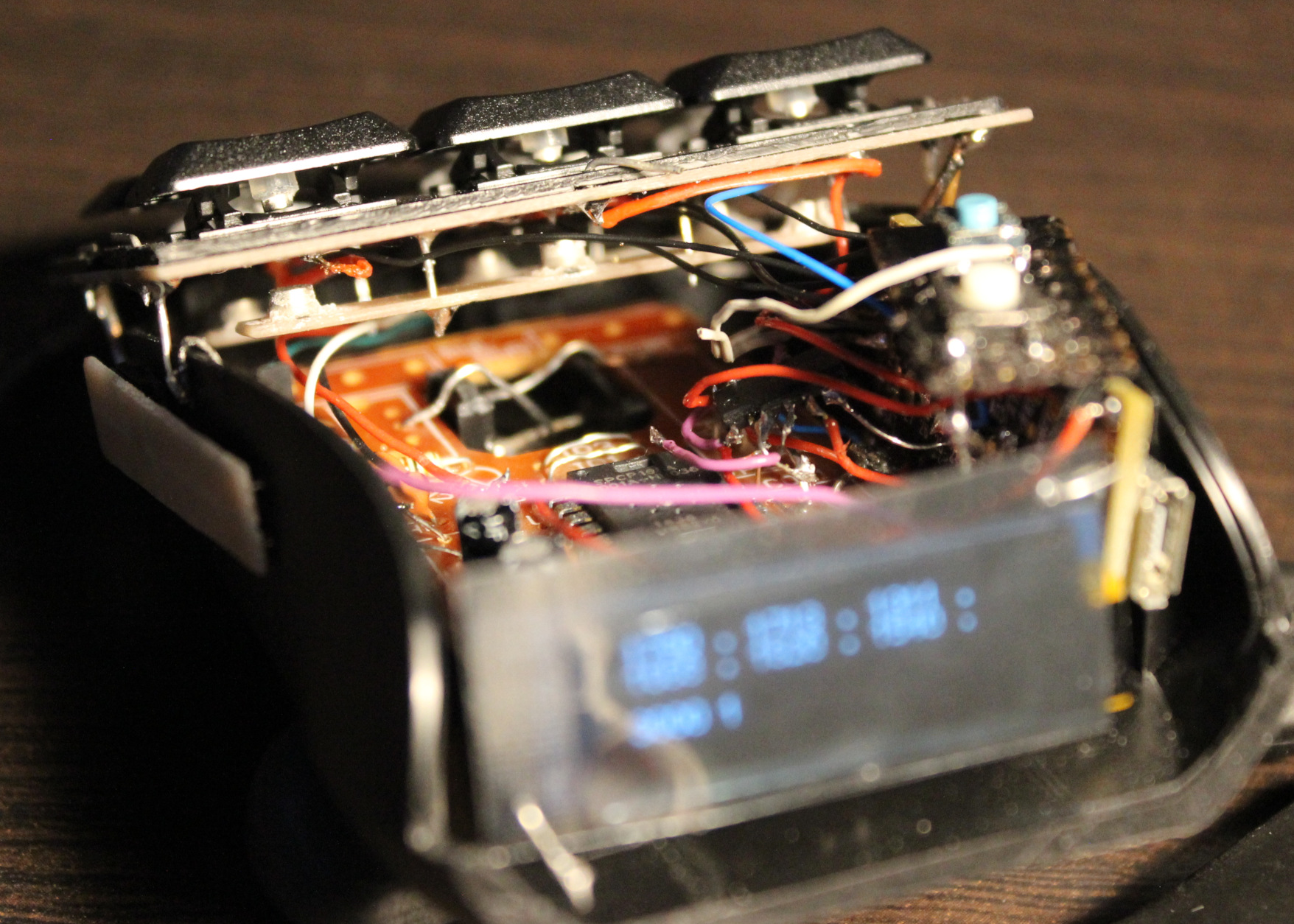
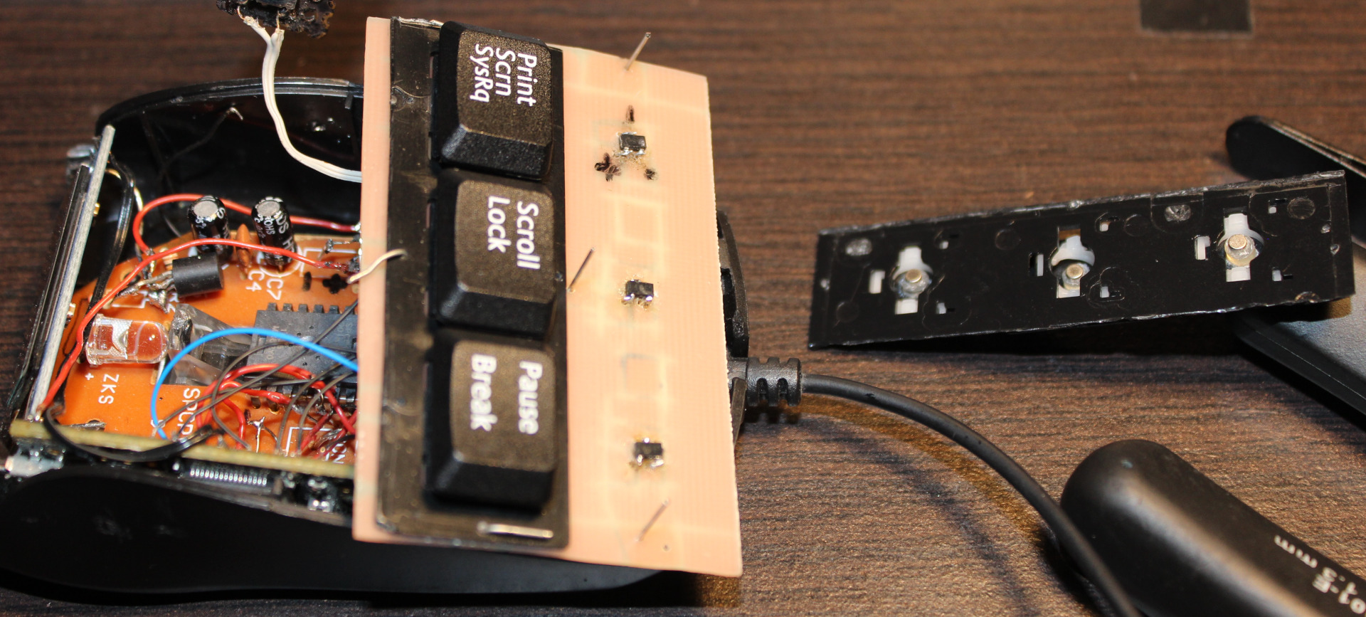
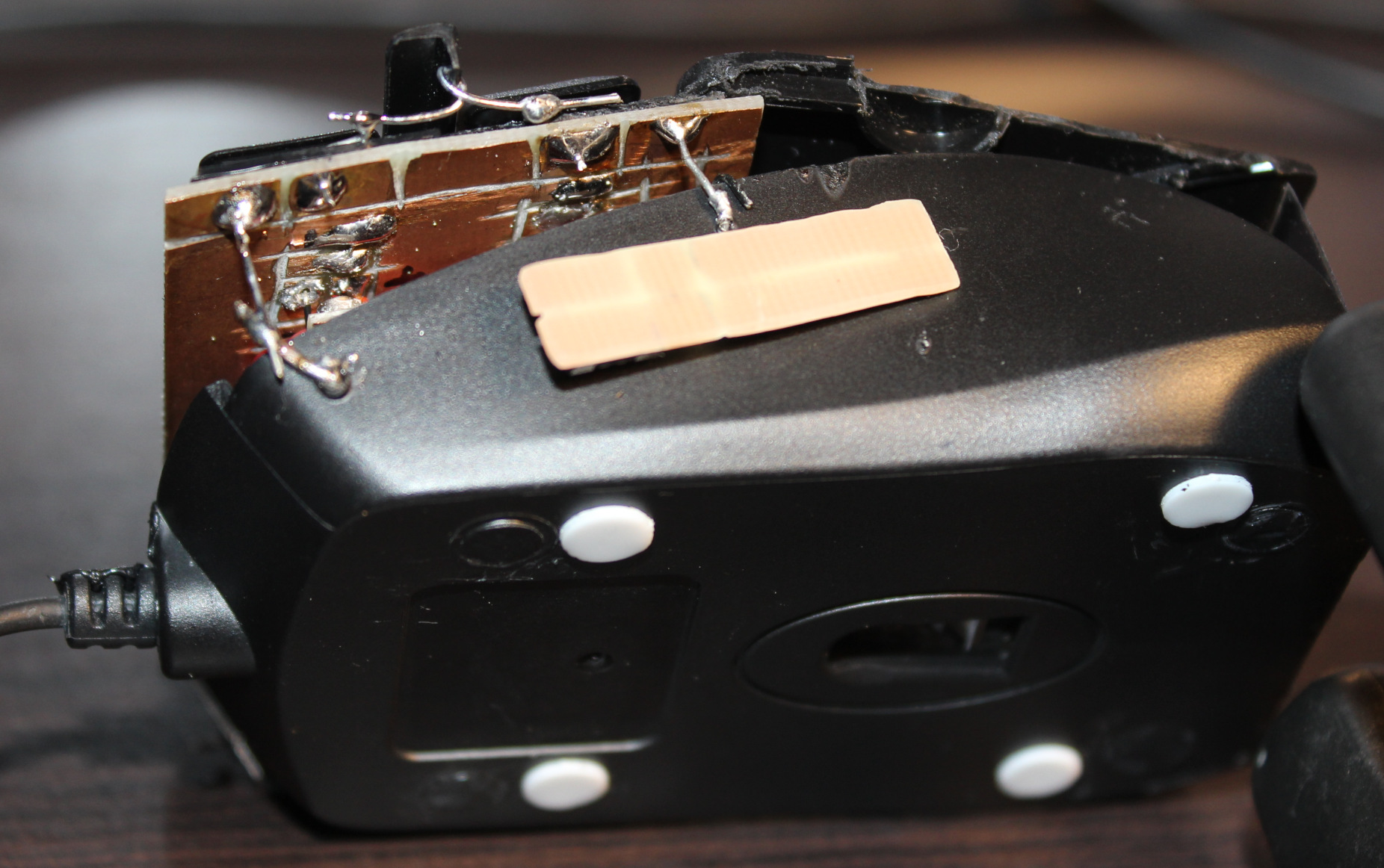
Mouse
Mouse is an old, wired Gembird model MUS-GU-01, it is small. Not very recognizable anymore after modifying. It has a SPCP168A optical mouse chip. It’s old (from 2010), so not very high dpi. Neither fast pooling, I even saw that L,M,R buttons are checked (by S0 signal) at about 370 Hz only (could mean a 2.7ms delay).
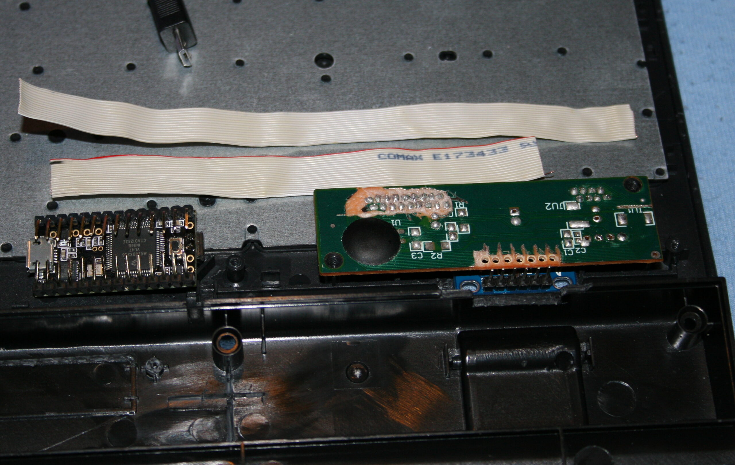
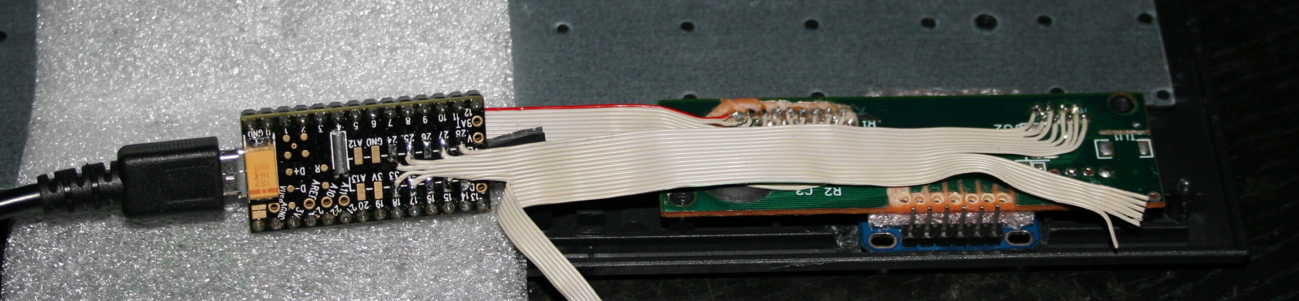
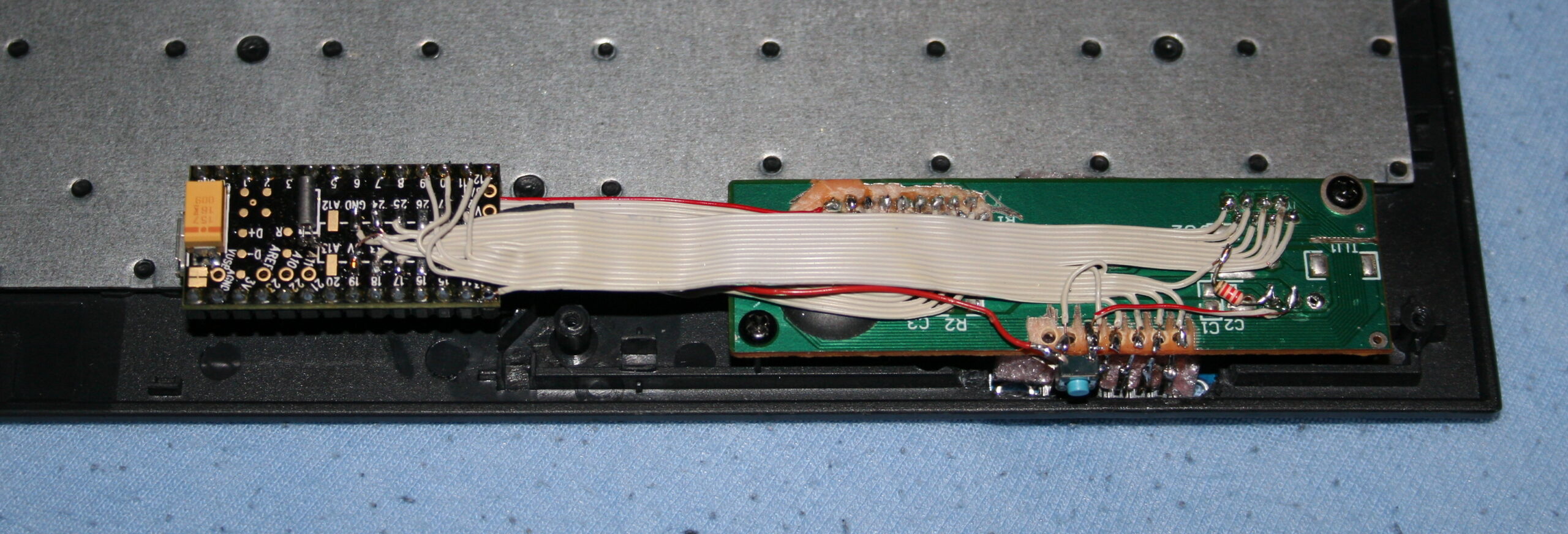
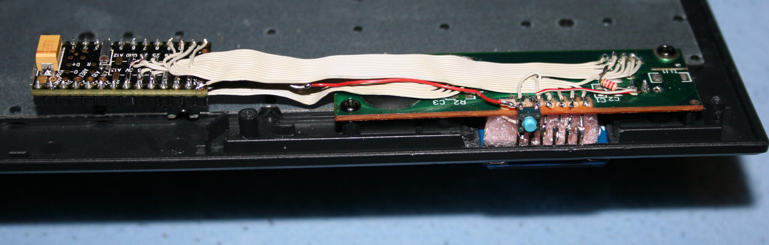
MCU
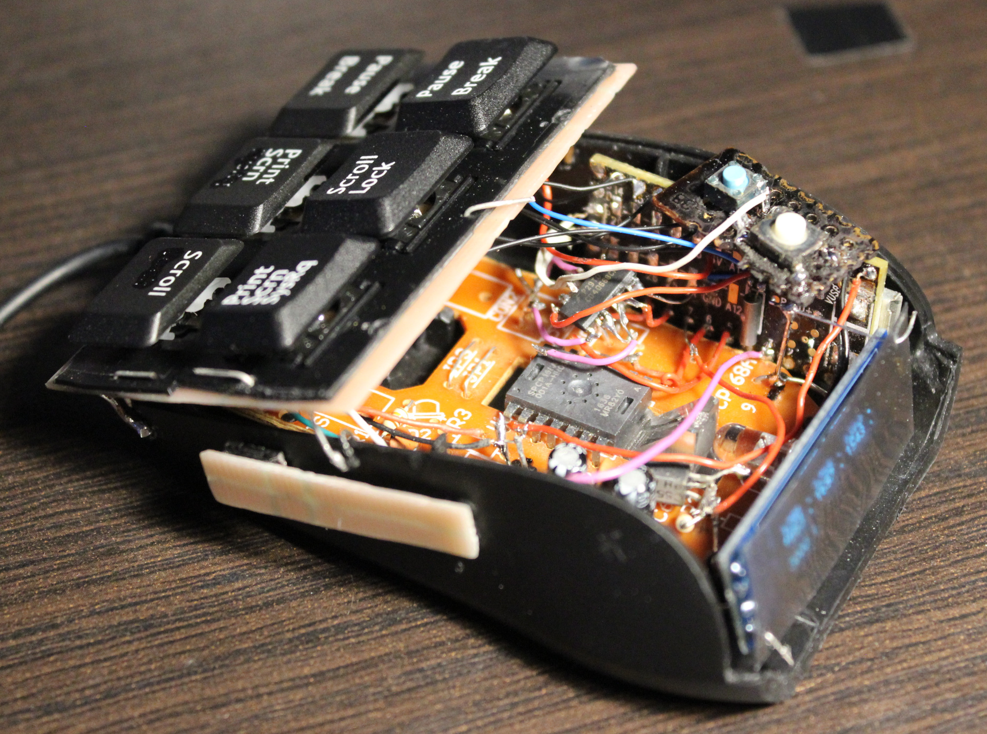
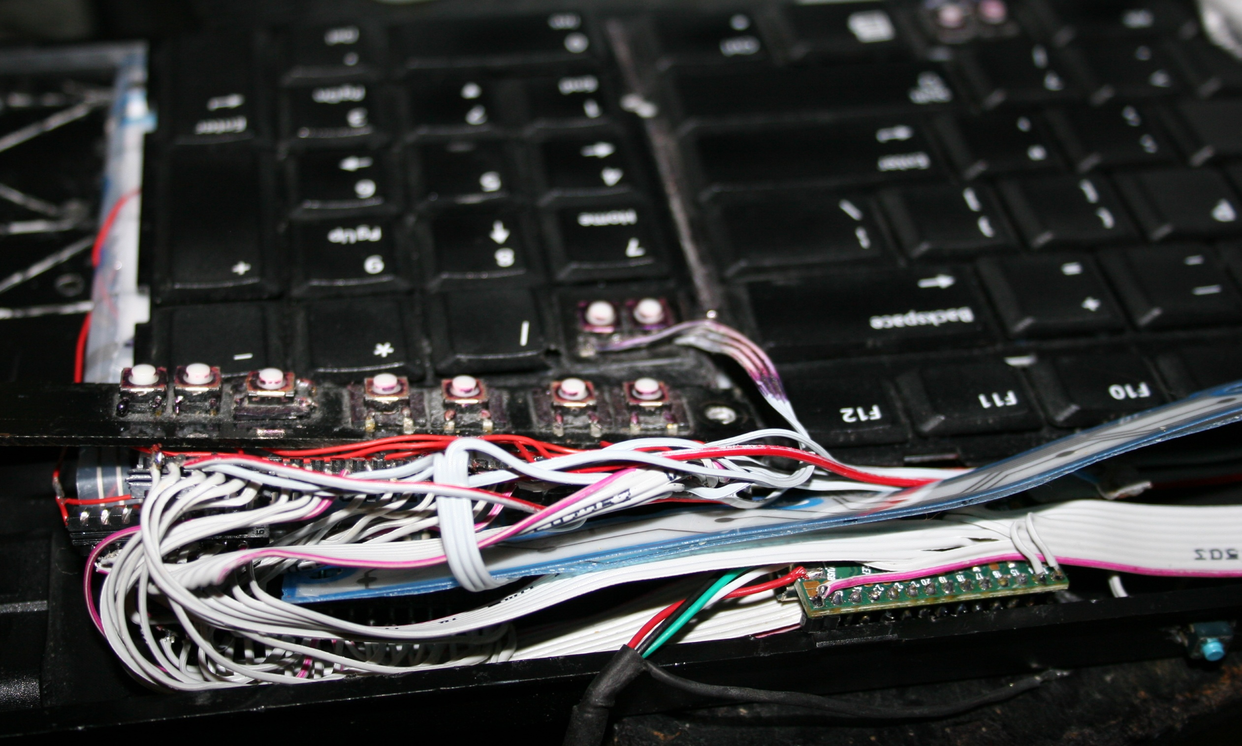
For MCU I used an old Teensy 3.1 I had from my old keyboards. Surely an ESP32-C3 could be a cheaper and better choice. And likely most MCU could do the job here: just read analog value from ADC from 6 hall sensors. Next I use a CD4066 (SMD, Quad Bilateral Switch). Its 3 analog switches are used instead of old mouse buttons microswitches. Triggered from MCU which reads hall sensors values with some of my code.
📊Features
So the mouse now has a few extra things:
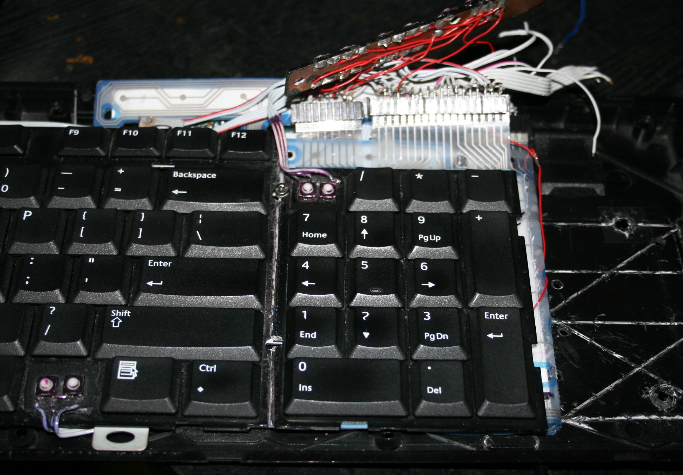
🎹Hall sensor keys, 3 x 2, so total 6. These are used for: – Left, Middle, Right mouse buttons – bottom row, – Double left click, mouse Wheel down and up – top row.
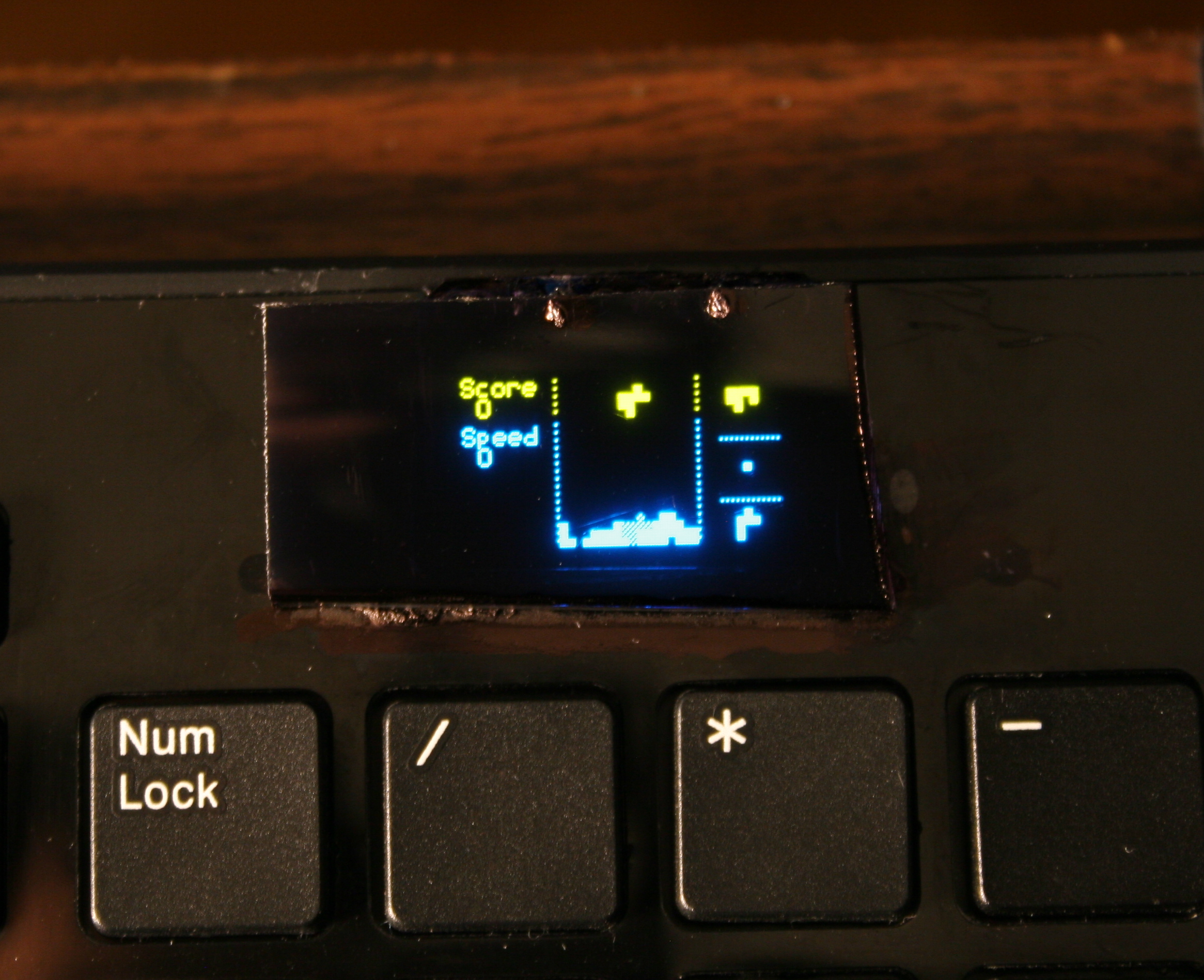
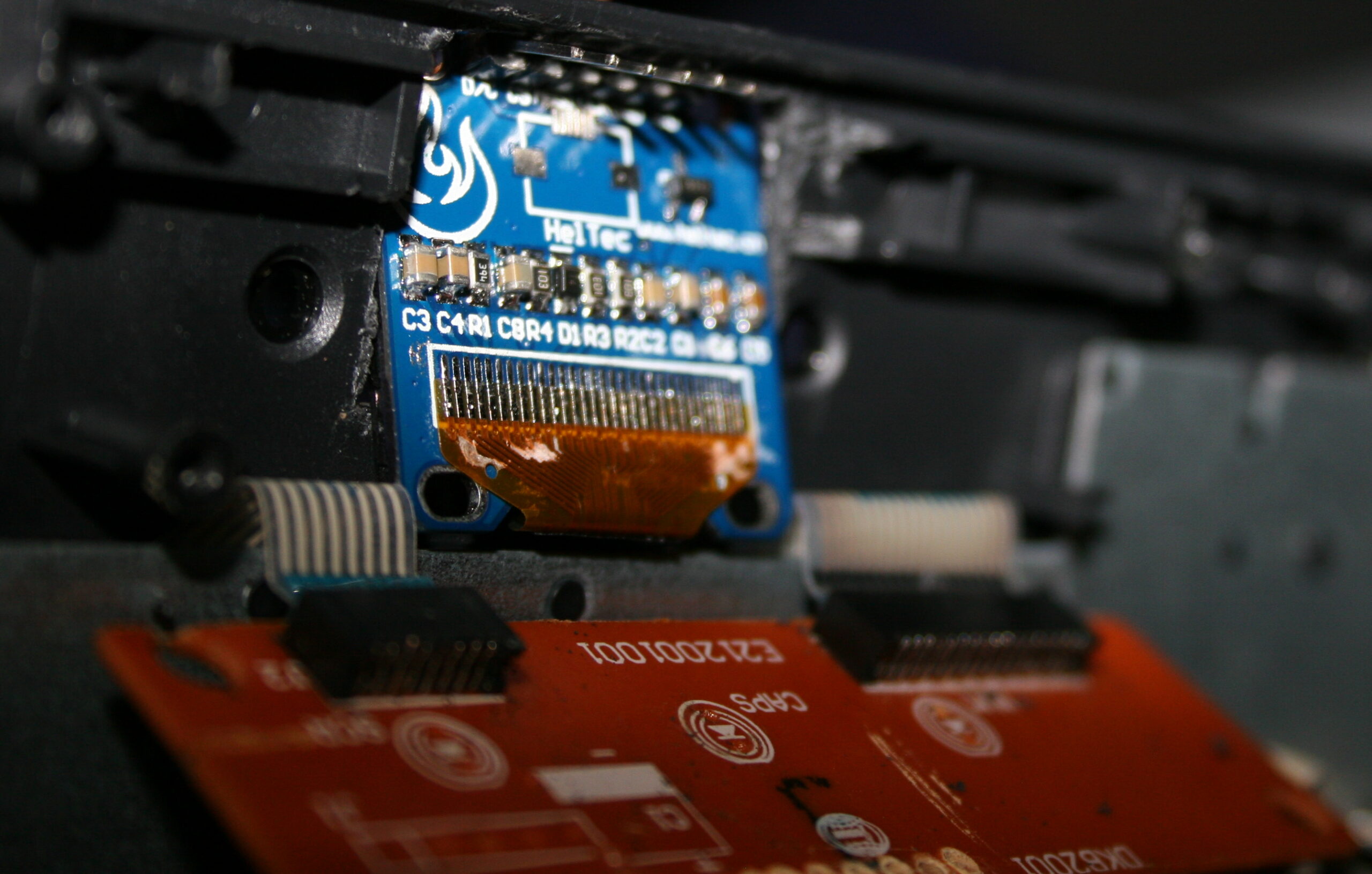
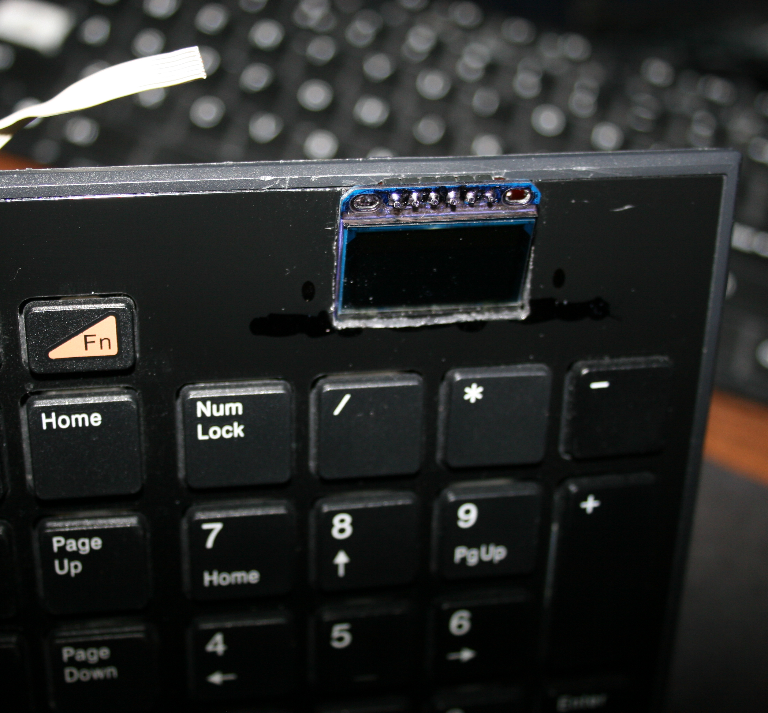
🪟A small OLED display, 128 x 32 (SSD1306), mono (1 color only). Only has 1 dim option, it’s always way too bright. I covered it with some foil. It’s usually off anyway. It is used to show hall sensor values for testing, and for future Gui with settings. It’s optional. It could surely work without it.
🖱️”Lift off” key. That narrow PCB on left side with has tactile switch (SMD, 0,5N force). When held it disables move movement (on PC) and any mouse keys. It is easier to press it than lifting a mouse. I mean seriously and it’s not common in mice yet.
👇2 extra tactile switches: – 1st for toggling display / Gui on/off – 2nd tiny blue for programming new code. There is also a micro USB socket for Teensy 3, needs to be there to upload new code.
📂Sources
Code for this “firmware” is here. Schematic image here. I called it MC1, from mouse controller, even if it’s not really one. Just code for those keys
📷Gallery
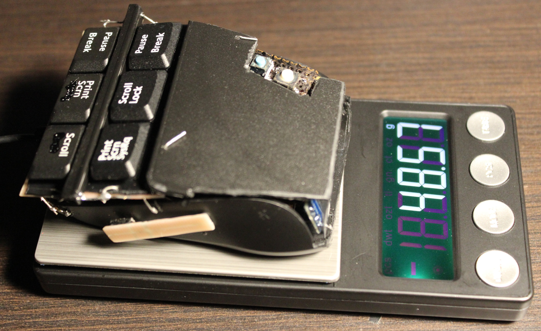
Pictures: outside, then inside, weights, keys. Later pictures show earlier versions, work in progress. Video here.
⌛Conclusions
Well, it surely is hard to get used to using it. I mean e.g. moving my hand from keyboard to mouse I can’t touch it or place fingers on these new keys, because that would already press them. That’s why this black plastic bar in middle and plastic cover are crucial, it’s the best first place to touch and rest fingers on it. So it will take a while. But I don’t want to use my old mouse already. It was nearby for a day and then vanished.
It was a good project for me. It also took me a longer while to figure it out and finish. I also wanted it done first before going after making a whole PC keyboard (100 not 6 keys) with such sensors. Probably my other design though, PCB made keys not this commercial scissor key crap.
I’m pretty sure anyone using just a default keyboard and mouse (with stupid 50 gram switches or even mechanical ones, that don’t go below 30 g I think), would likely go nuts with this mouse.
Would I recommend it? No. Unless you know for sure you’re after the lowest actuation force in keys. And that could be the case if you have an injury that makes it hurt to press the default (and so stupid) keys. As for me, I want to avoid injuries and fatigue (from using way too old, ancient switches and keys continued just for profits). That’s why I use it.
It is a joy to use even if tricky (you can’t touch this🎵) and a relief, less tiring when repeatedly. It was way to many times of me pressing the freaking mouse wheel (instead of an extra button) or even tedious scrolling. Instead I got a touch-key (for middle mouse), same like all other 6 now. Also keys to touch and hold, when I want to scroll mouse, not turn wheel repeatedly like a knob or something. I can even touch the Left button on mouse nearby with my smallest finger if needed. Lastly the “lift off” button on side is honestly like a must for each mouse. I just need to move it closer for thumb.
The mouse weighs about 48 gram now, less than my previous half of old Logitech G5 which was 62 gram (after cutting off, visible on right of picture here), so it’s also better for me. I have plans for G5 to also rework it same way. I already removed lots and checked that 25 gram is the minimum working stuff, that’d need my keys and other stuff.
There is also one thing I didn’t do: making it more ergonomic, e.g. having tilted keys at some angle. Well that’s for future project or update.
DIY
Lastly, and obviously this thing ain’t pretty. Was never a goal for me. It rather screams DIY. And it’s IMHO the only solution, not anything commercial. With DIY I got parts reused, I can fix, adjust or modify it later, etc. I set the budget (or price). It gives freedom and low cost. It promotes learning, not addiction to buying (consumerism). And most importantly for me: it makes it possible to have stuff that isn’t commercially available, and probably won’t. Crucial everyday useful things and software. I recently found this channel (mainly DIY RC toys) very inspiring and enlightening. There are plenty of DIY projects now e.g. on hackaday.
The project doesn’t require 3D printing or company making PCBs. Surely it could. But for me a 3D printer seems nowadays like a too popular, way too expensive tool, or toy even. And so many projects (e.g. here) just looking like a commercial for 3D printing. But yeah other times like a quick way of sharing your design with others.
I did PCBs just with my small drill, used with a dremel diamond cutting disc. I use it for cutting PCBs and for removing/trimming copper. This way was cheapest, I didn’t need to pay any company, and I had all stuff already at home. Of course if I had to do 3 or more mice like this, I’d go the alternative way.
I describe here my latest PC’s Water Cooling (WC, but not that WC 🚾🚽). Done by reusing previous PC WC components and partly newly made by DIY approach. I also write about my experience from doing and using it and remarks about the parts. Ending with WC comparison (and why it’s been always better for me) and conclusions of the project as usual.
📜Short history of my my WC
I already started with WC for my PC in 2004. I bought a full WC set, it was cheap and low quality. Later I replaced radiator, as it was the worst. I even tried WC in PSU, but that was nuts. My previous project 2004-2022 has more history and info.
For over 15 years I had 3 things: PSU, radiator and water tank/box/reservoir separated, behind PC, not inside. Was rather immovable. Obviously not great. But I didn’t mind this flaw, since I never moved my PC.
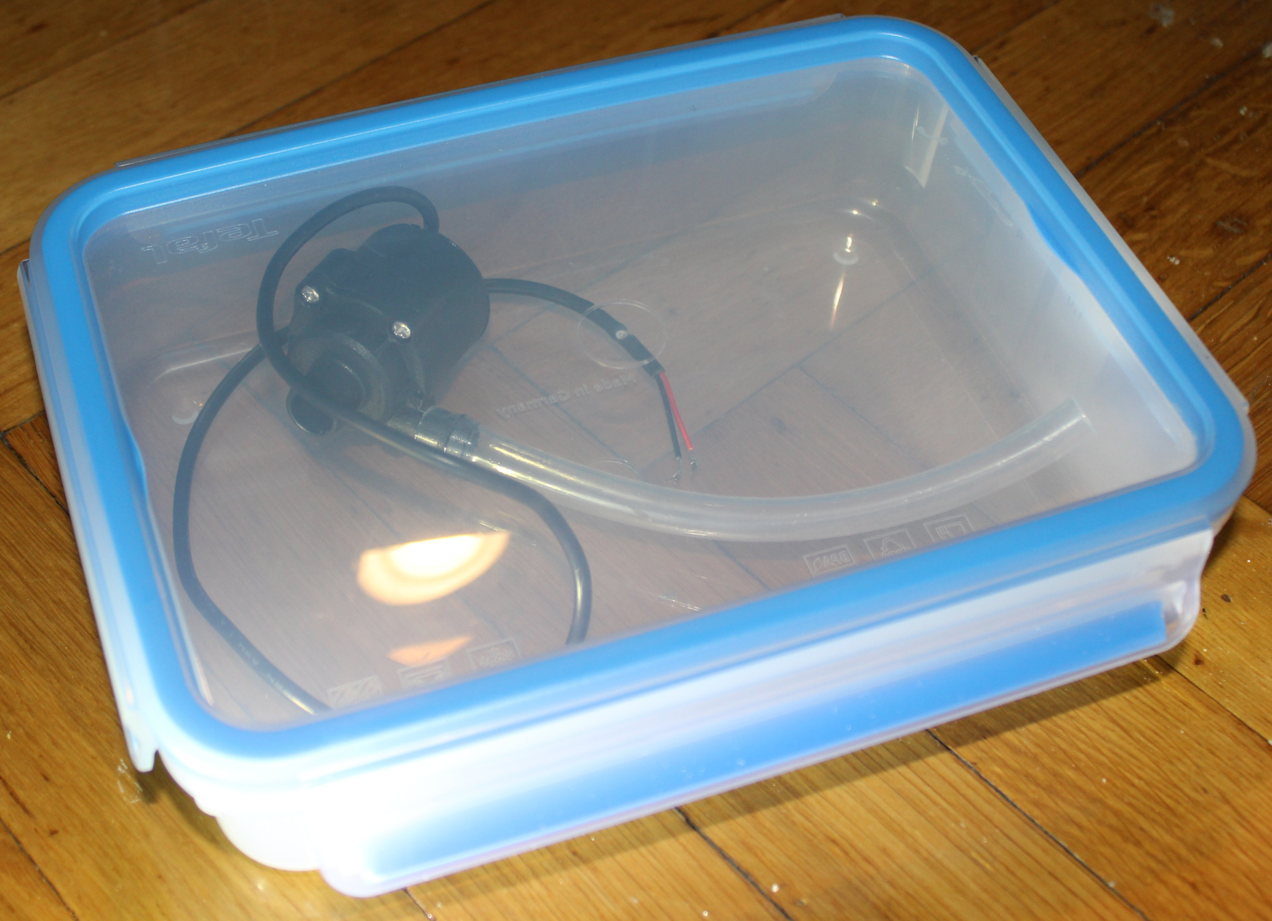
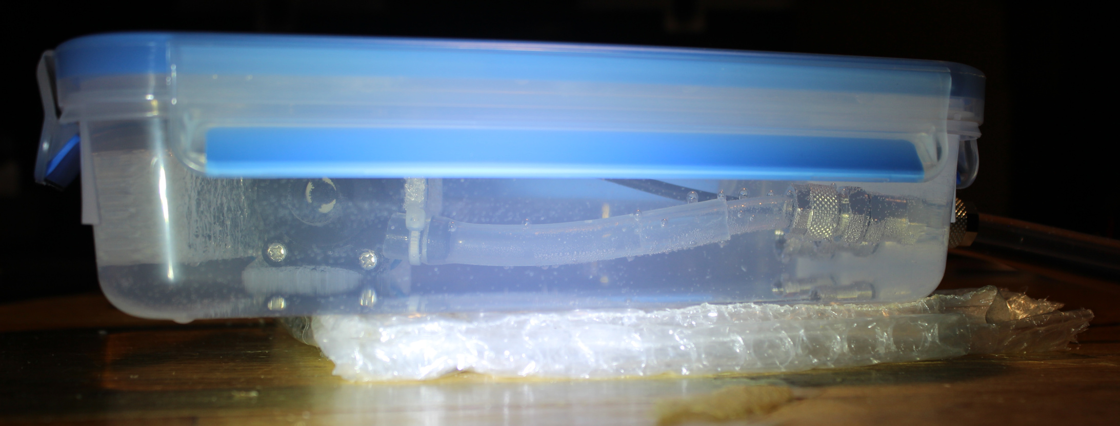
As for water tank, the pump was in it. I made it quieter by tilting (picture). The pump was really cheap, always at full speed and using 220V (that’s bad), 10W power. But it worked well for about 10 years until it stopped. So water tank was better, quieter outside, since pump’s vibrations didn’t amplify, when put tight in PC case. Also easier to fill, add or replace water, etc.
For years I had radiator outside PC too, just hanging, attached to my desk, under which my PC always is. Later, in previous project I’ve mounted 3-fan radiator/cooler on the PC case I had (picture) and put that big PSU inside, leaving only water tank outside, PC was possible to move. I had previous PC for 12 years, until I finally decided to upgrade all hardware.
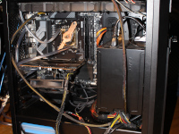
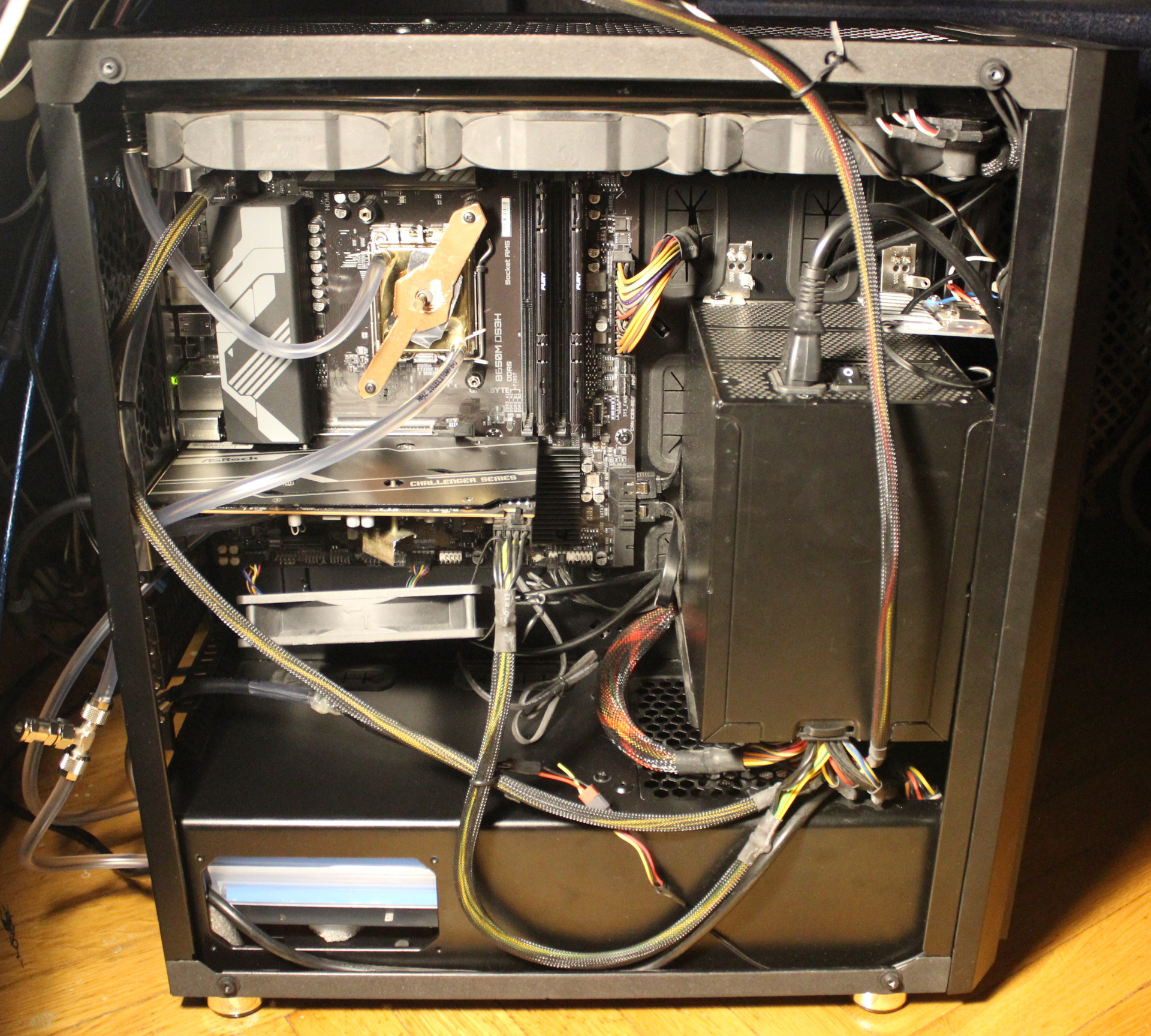
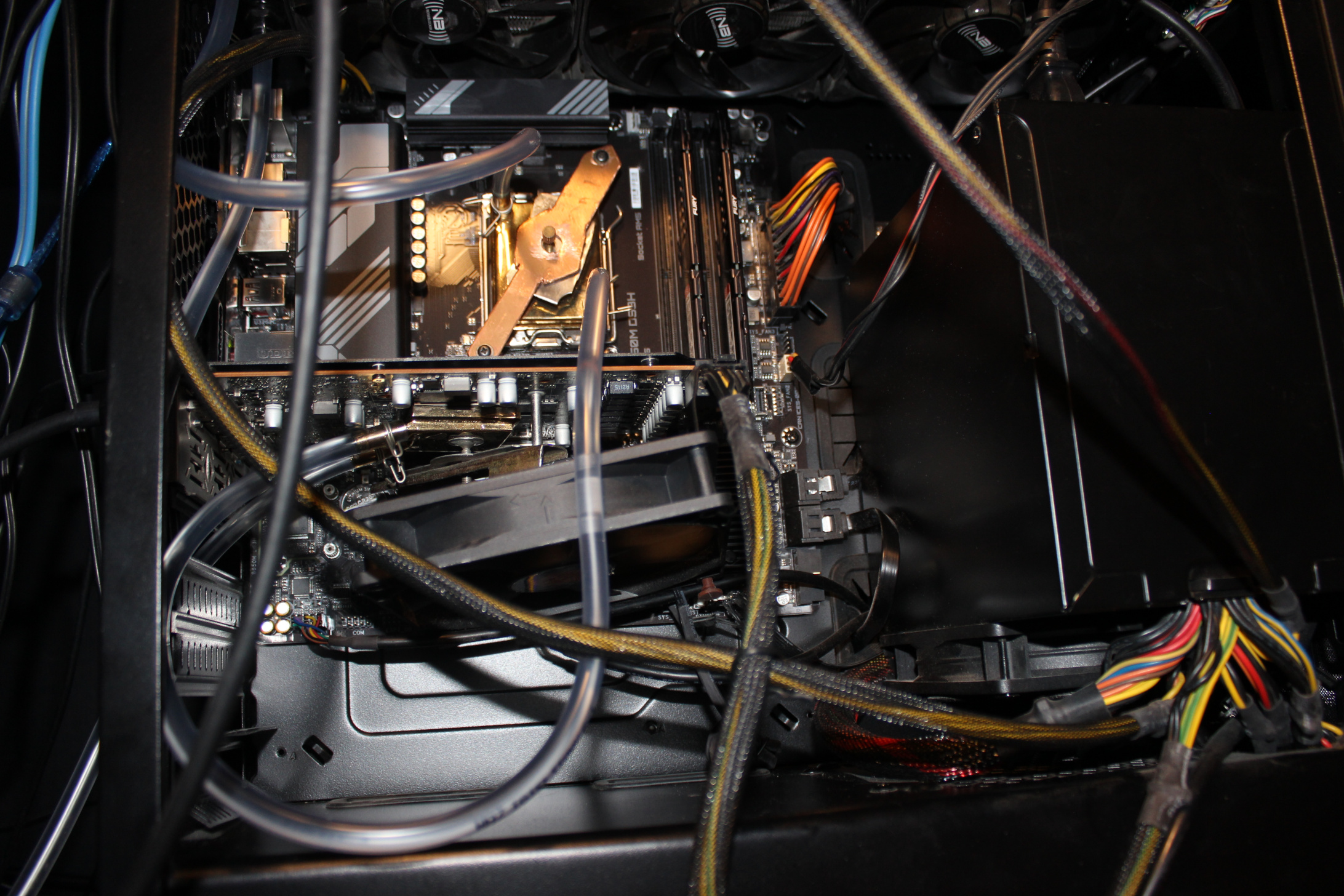
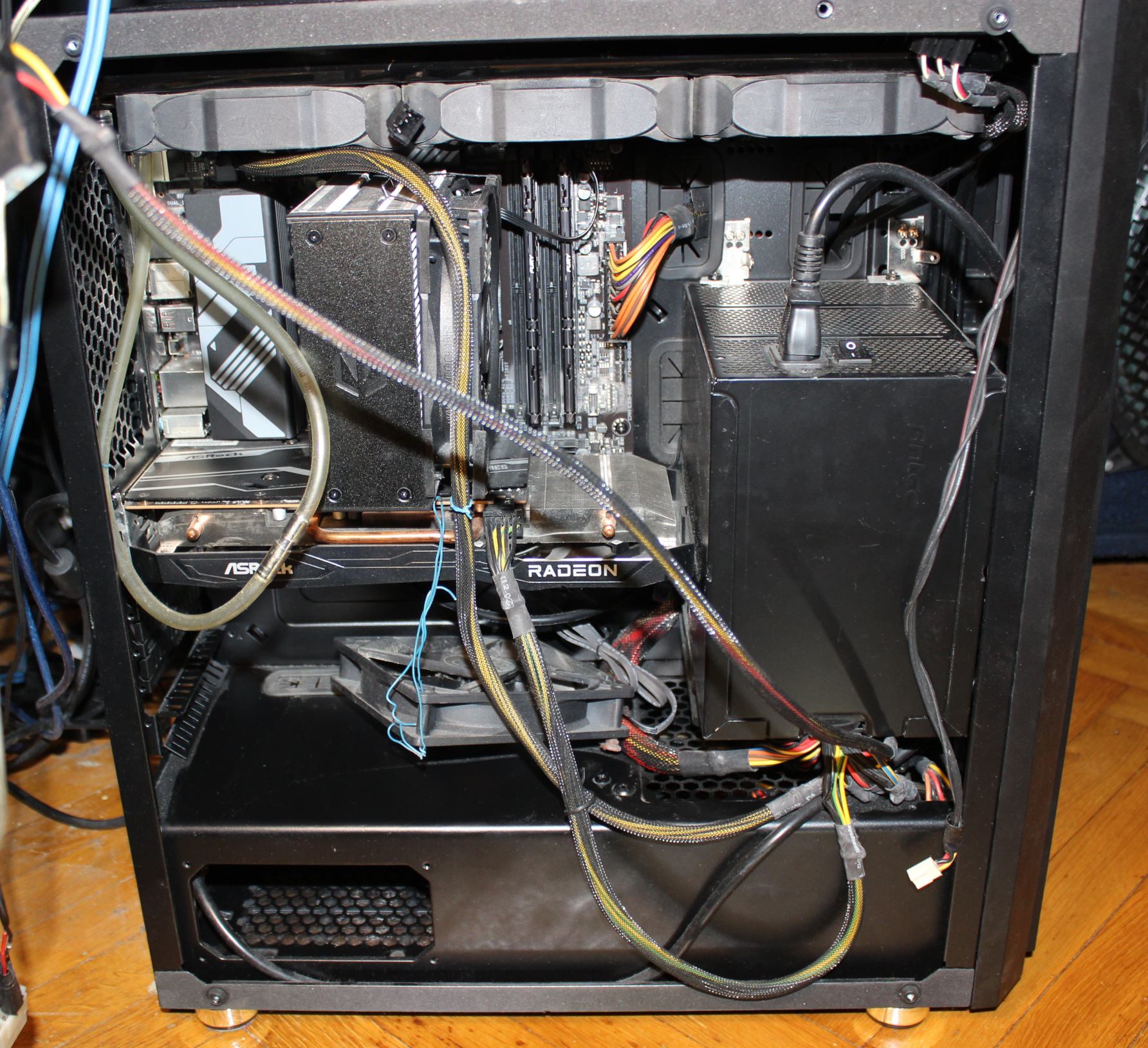
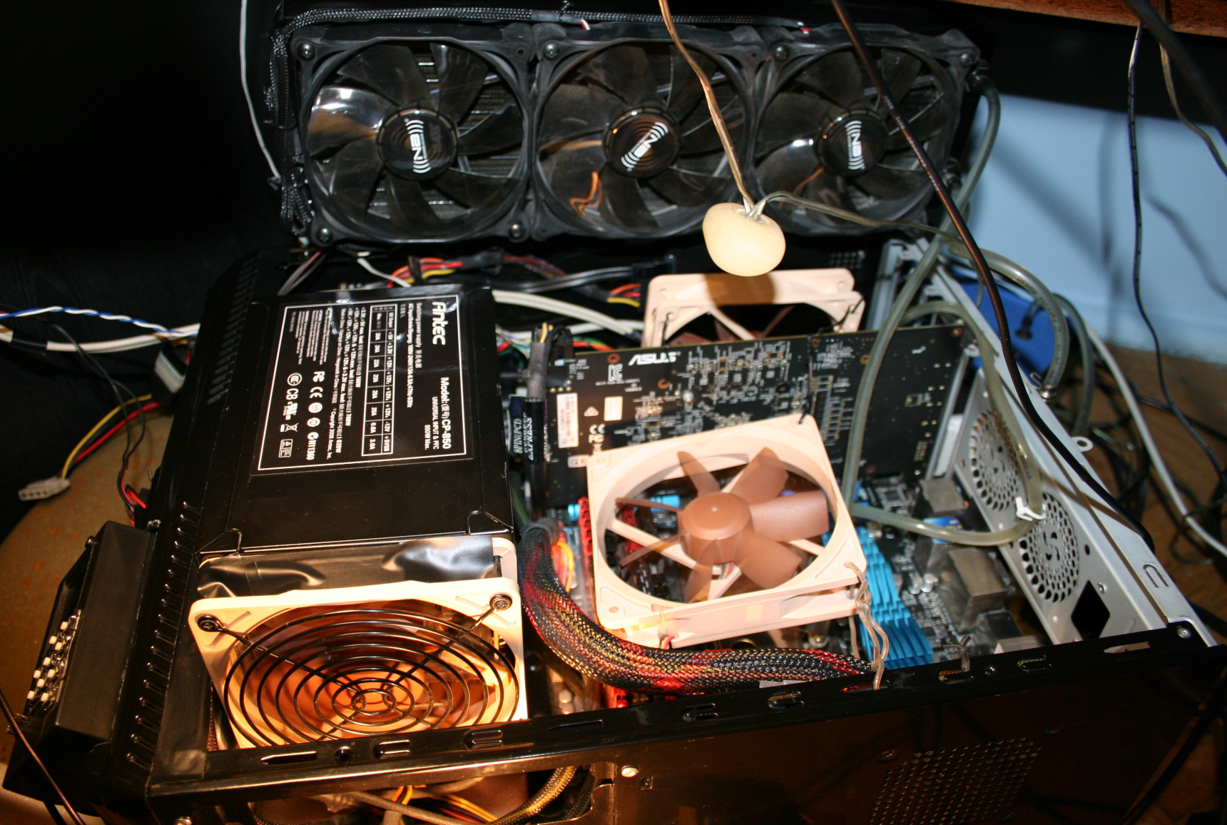
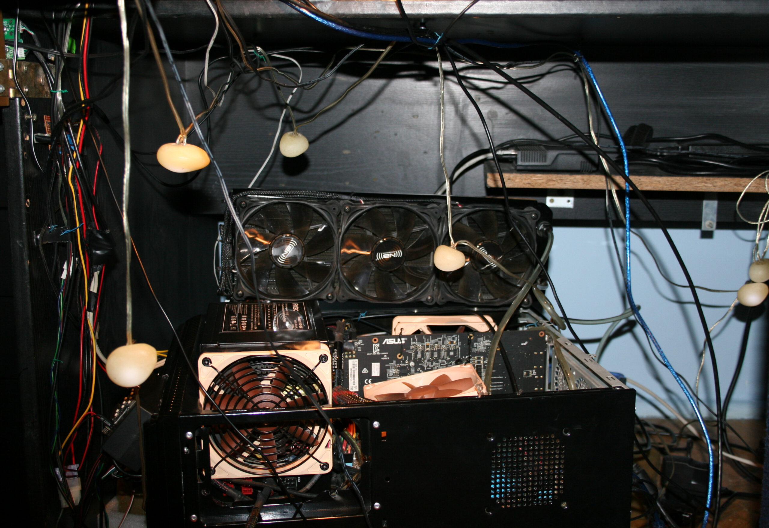
When I bought a new PC in Sep 2023 (I pick all parts myself), I also chose a new PC case. Only PSU was left from the old PC. I measured and planned before, so that this big PSU and new GPU would fit inside (barely, picture). I got a smaller mainboard this time, it’s better.
I used this new PC for a long time with air/fans cooling, until finally in late Apr 2026 I had enough of that CPU fan noise and converted it to water cooling. Why did I wait so long is because I was busy with Stunt Rally 3 and as always did no other projects while developing it. Also because I wanted to be extra safe, there is always a tiny chance of a mistake and damaging something.
🔍Details
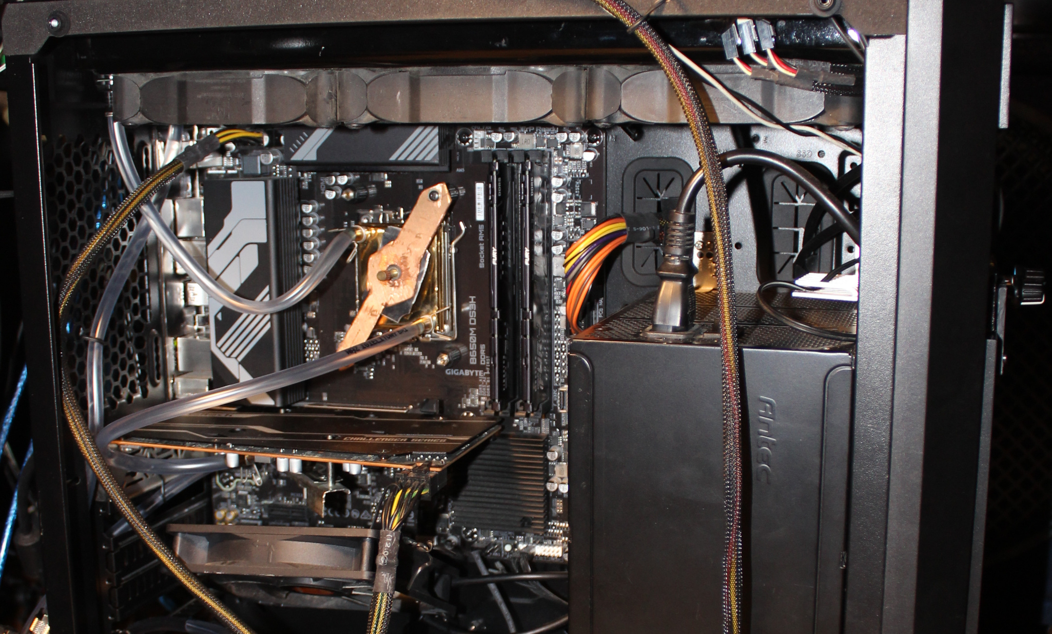
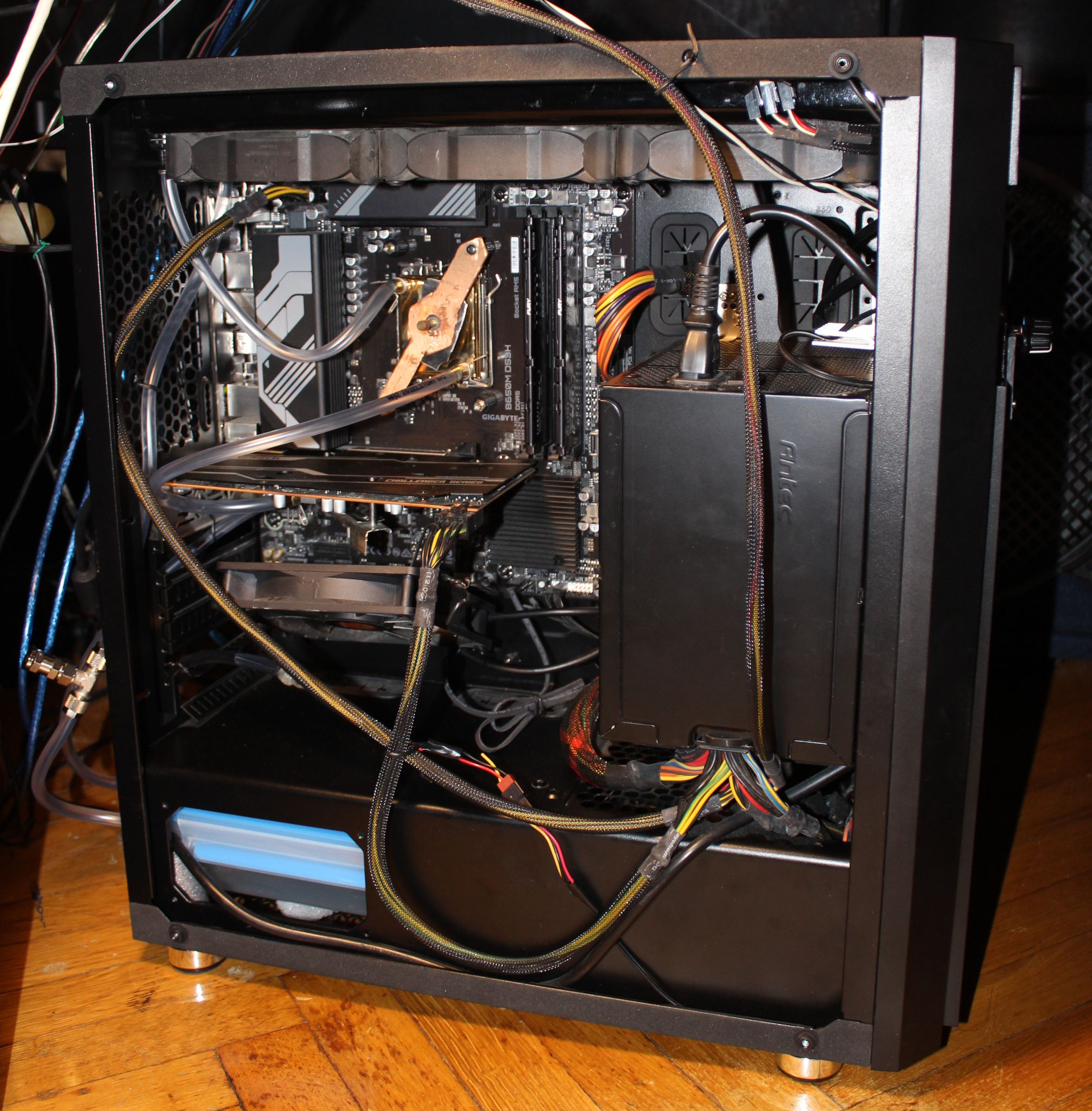
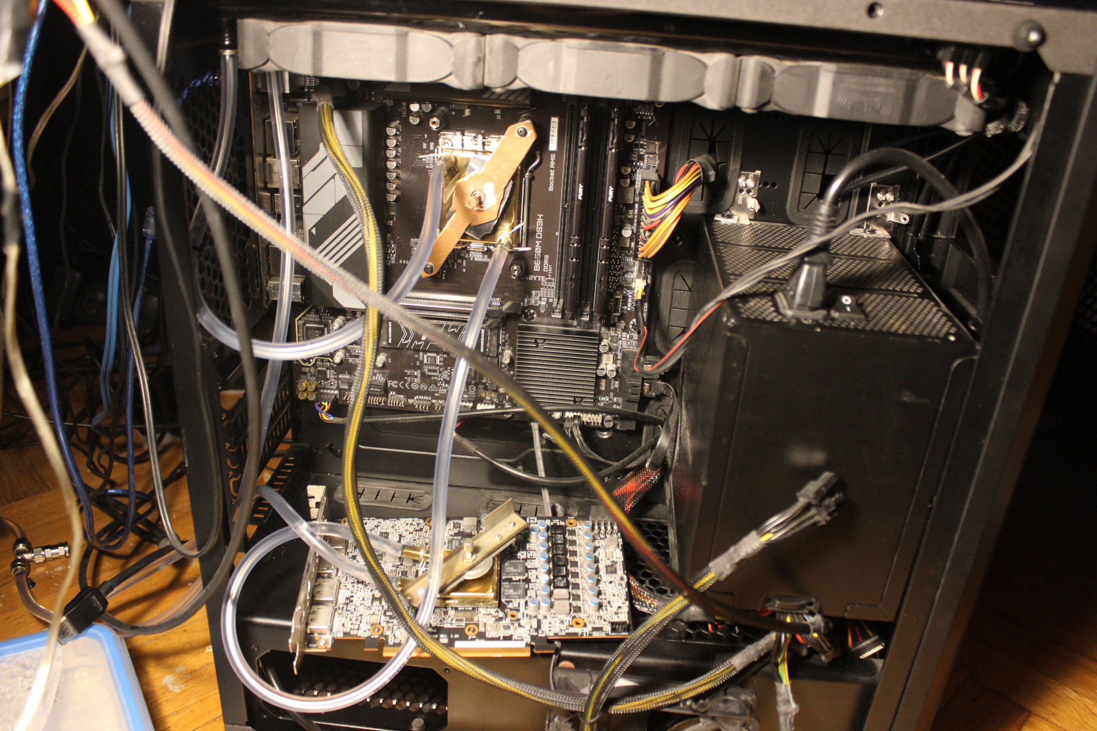
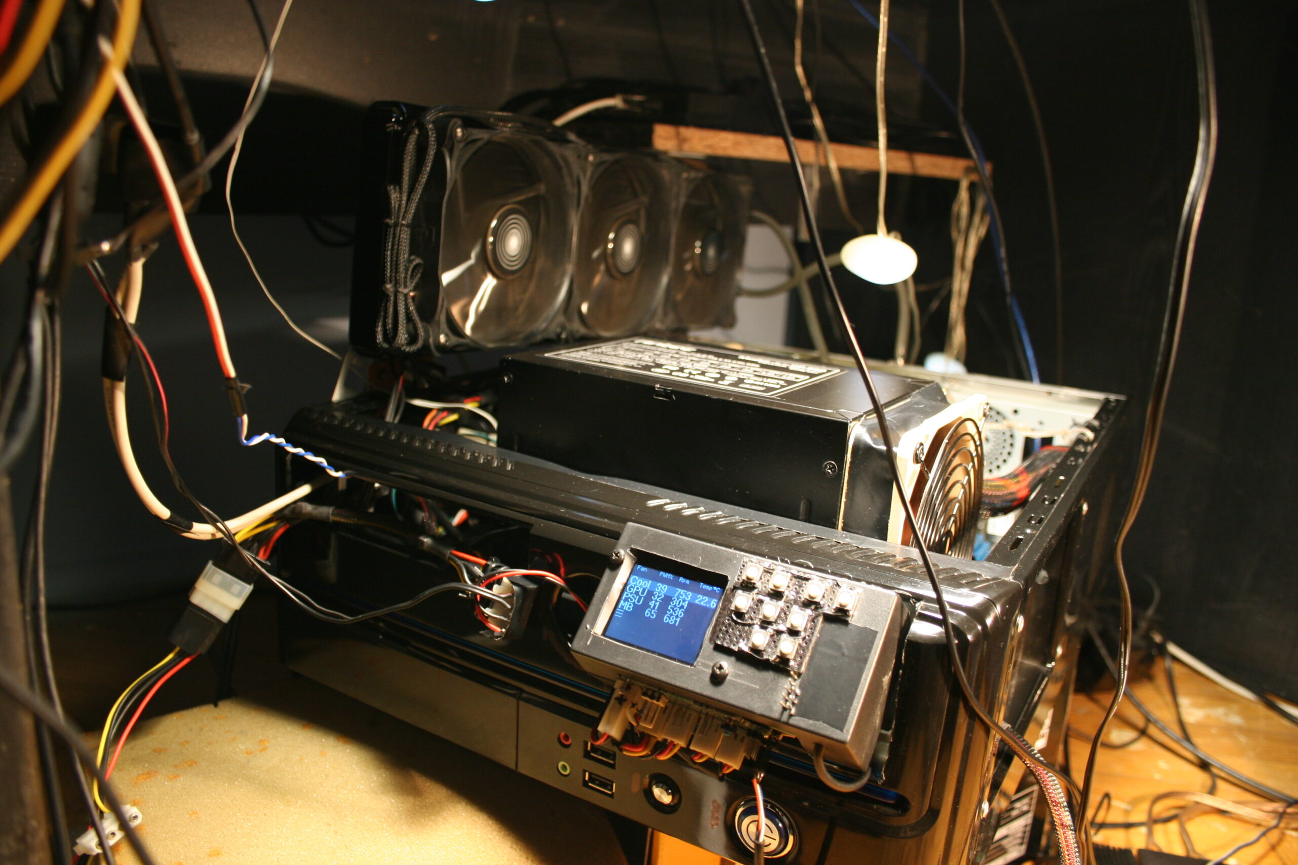
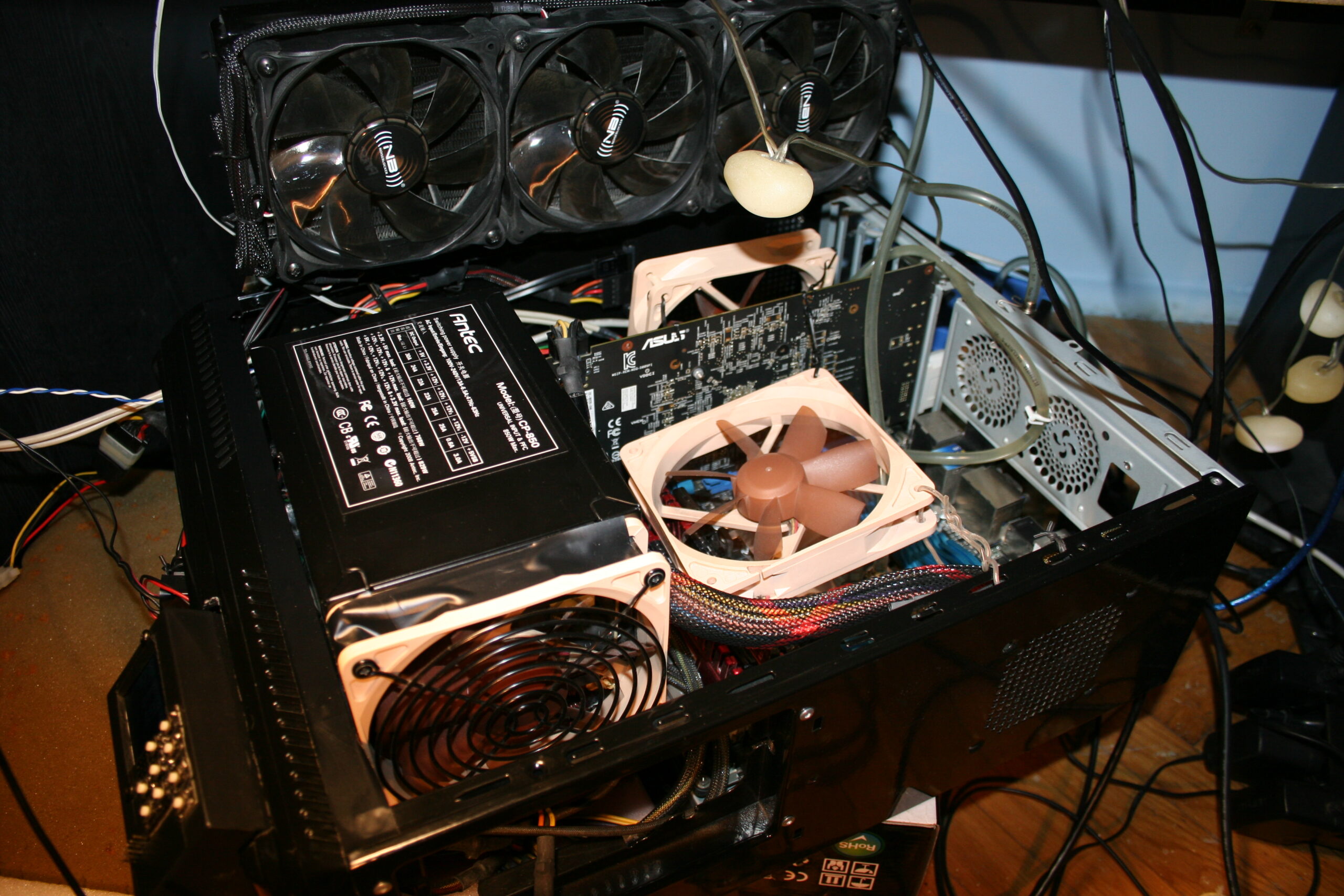
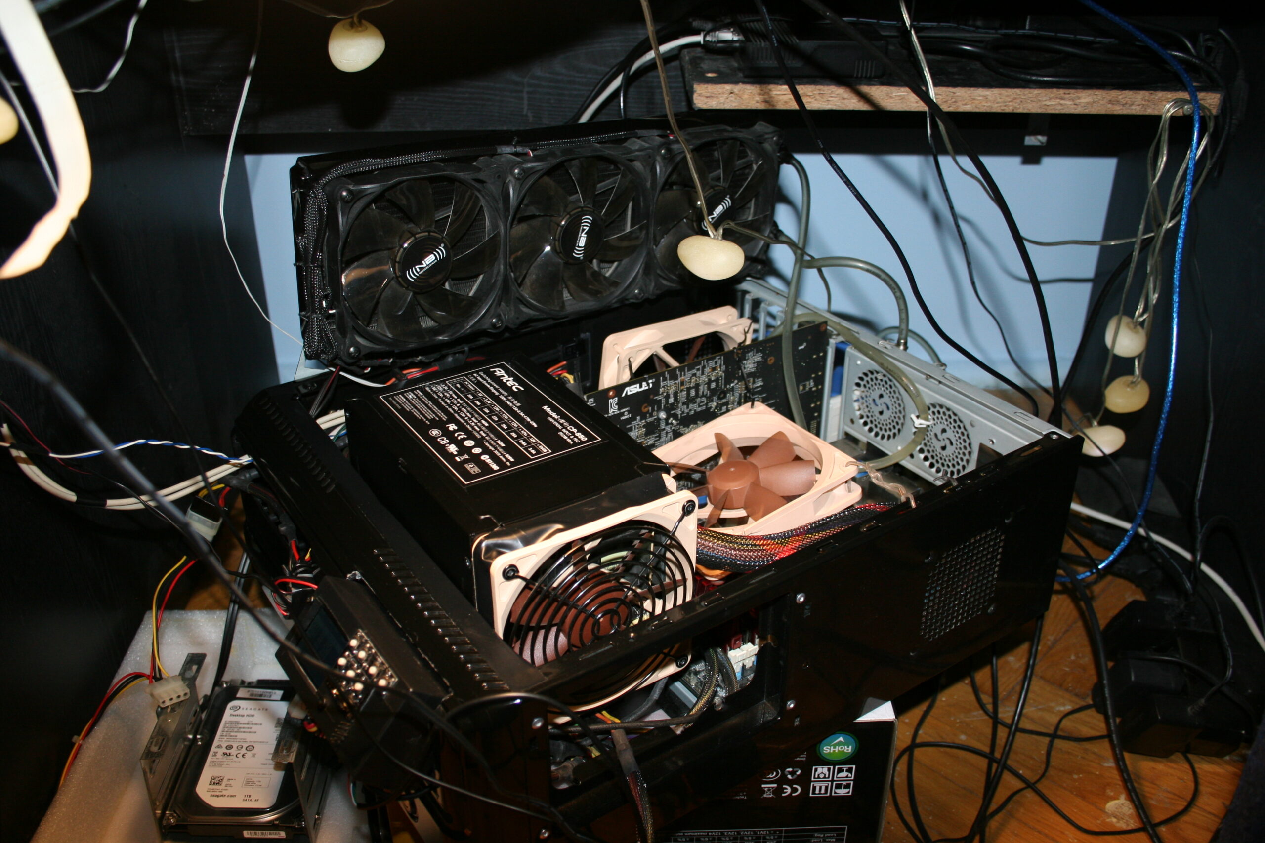
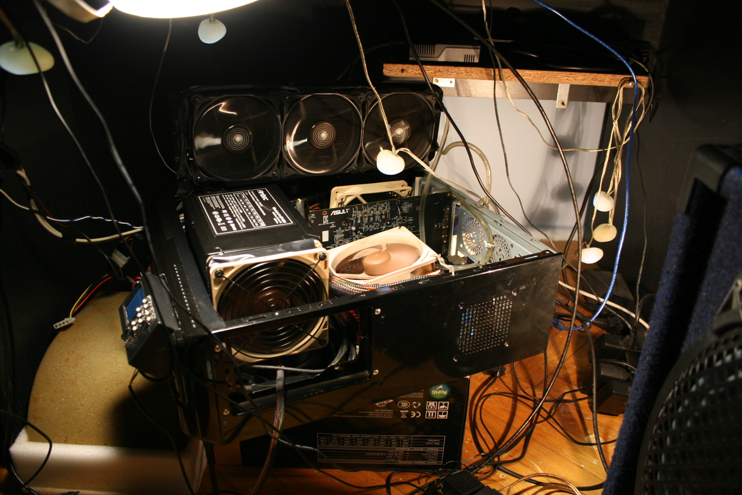
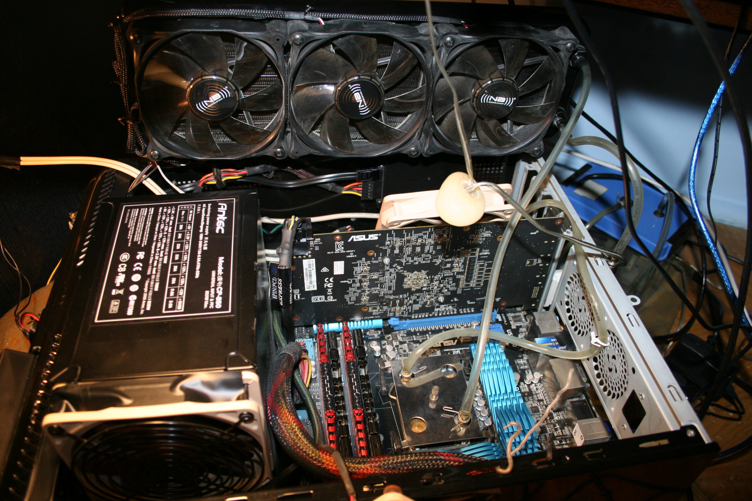
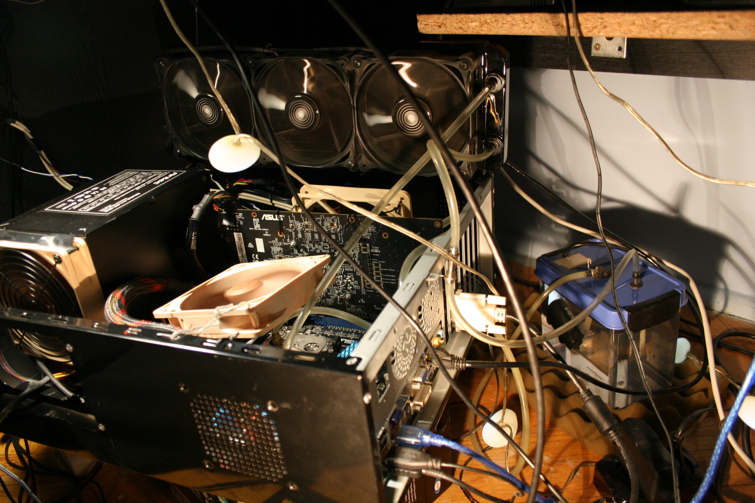
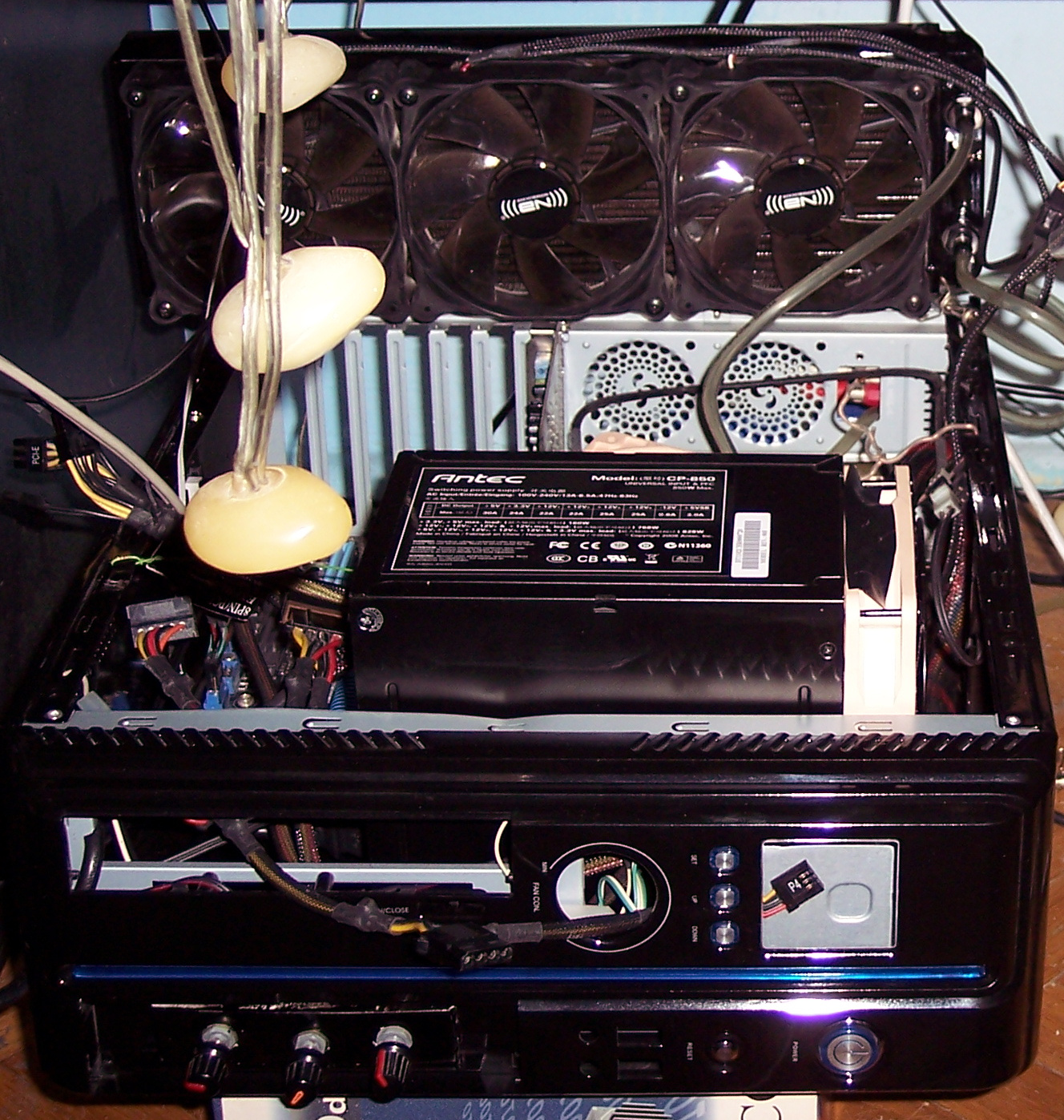
This time I managed to put everything inside PC case (WC radiator, PSU and water tank) even without cutting case. It is a huge improvement from old times when I always had PC stuff out of its case, just lying around on floor. I list now the main, cooling components of my PC with more info.
PC Case: Thermaltake Versa H26 (review link, official site, more pics). Weighs 7 kg already. I like it a lot, maybe because it was so long (like 10 years) since I got a new, small PC case. This new one allows many customizations and adjustments. It has place for WC radiators, back space for cables, etc.
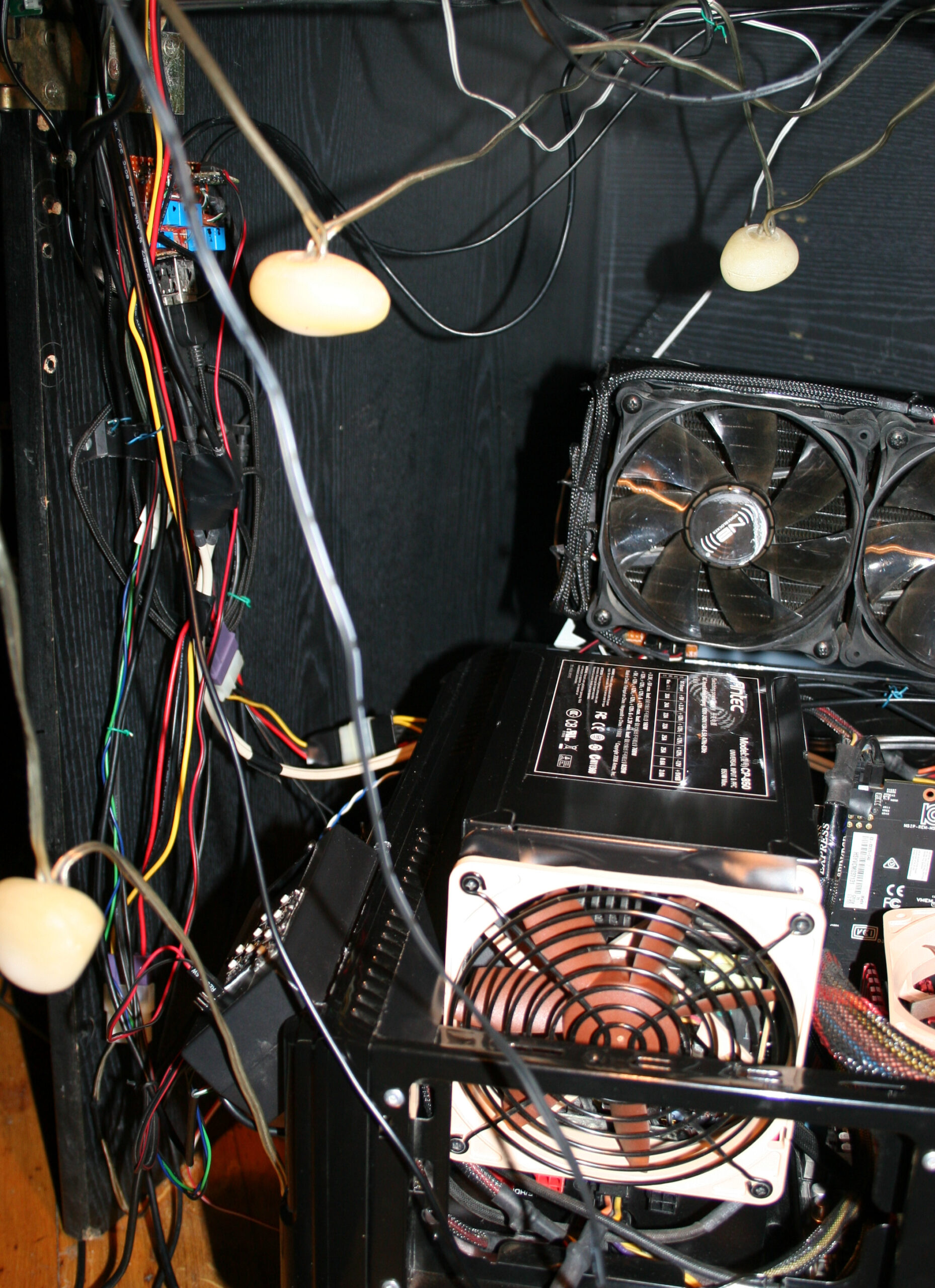
That big PSU: Antec CP-850 (review link, video, video 2), from 2008 (wow, happy 18 years man🎉). Quite big but still awesome. Has a lot of space inside for good air flow, from a slow rpm fan (12cm) on side, not on top, is also quieter this way. It can give way more power (850W) than I need (like 100-300W), so it won’t get warm or loud ever. It weighs 3.2 kg. It is 80% power efficient. OFC now they don’t even have it on their website and don’t do such big PSUs. Pity, the design was way better and ahead. It needed some effort to put it in the case, and I mounted it on right side of motherboard, not in the usual bottom place. Obviously like before, I wouldn’t consider getting any expensive, huge PC case that would fit this PSU. Maybe that’s why this size factor didn’t take on. In my PC, likely just a regular size, quiet 650 W PSU would do. I’ll probably never know since I don’t need to change.
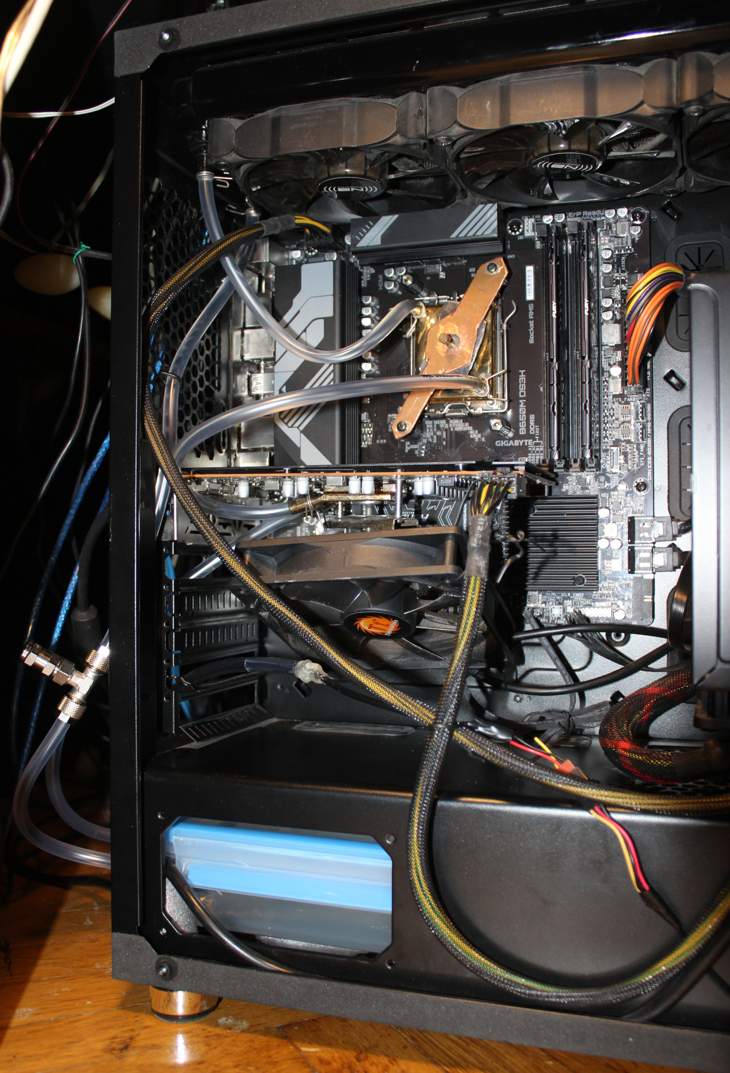
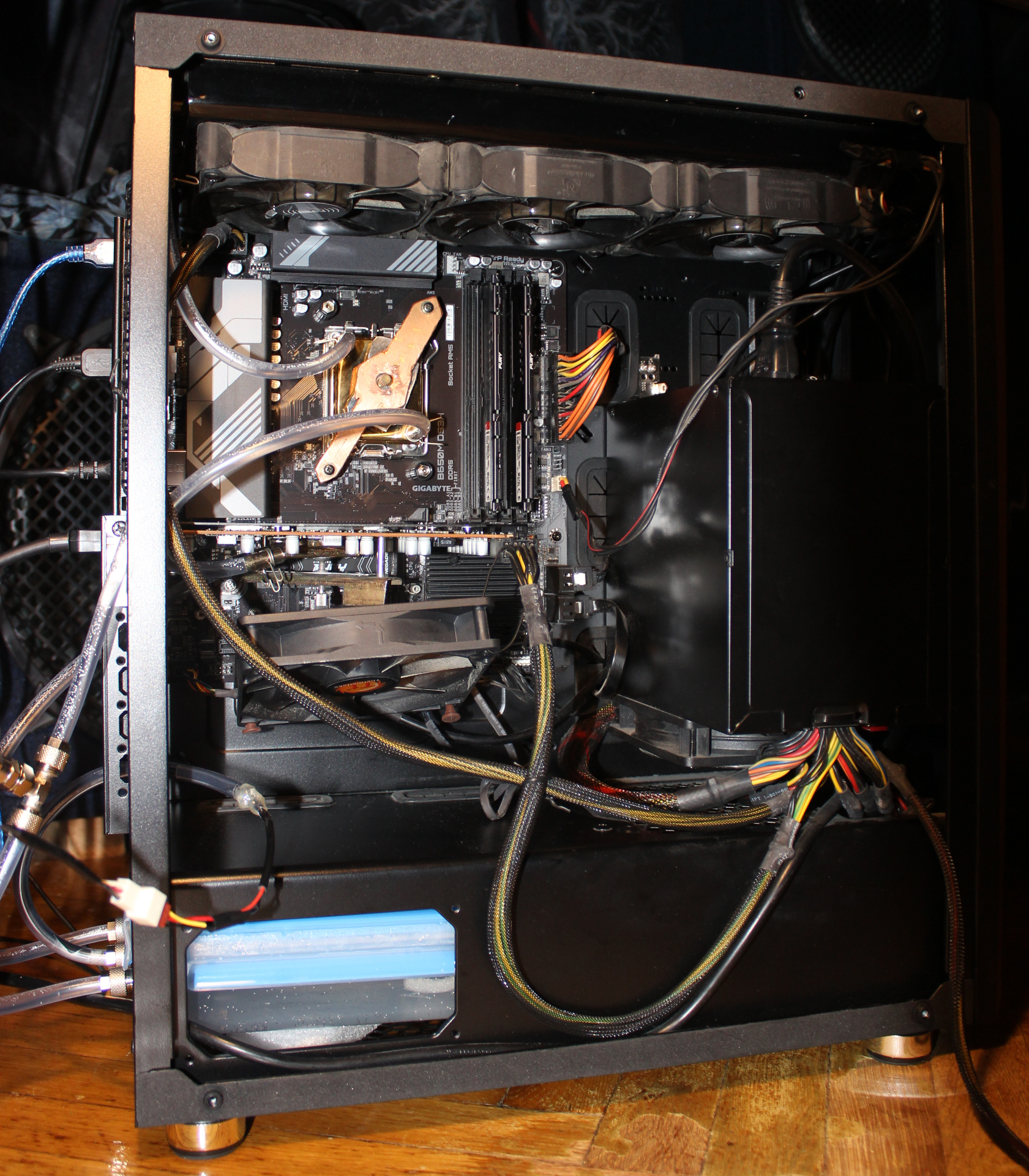
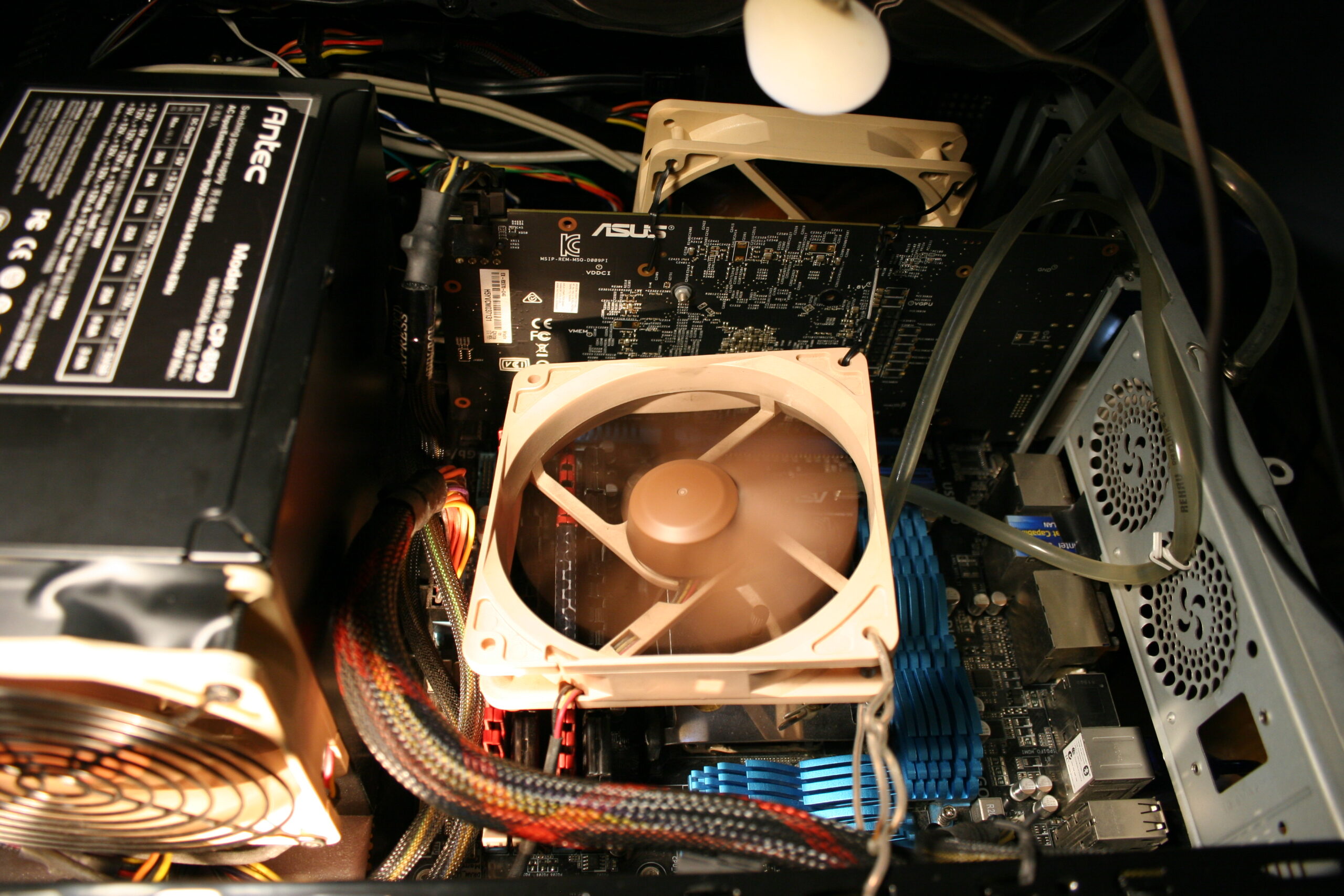
Radiator/Cooler: old Black ICE GT Stealth 360, for 3 fans (12cm diameter). Fans: on the radiator I got 3 Noiseblocker fans (to be cheaper than Noctua and black already). They came mounted on rubbers and sound okay at low rpm. But not when higher, I can hear some motor noise. Also at certain rpms they make some ringing/resonance like sound. Noctua was quieter but I hate their colors now. I think I’d add a line to that song🎵: I see a Noctua fan and I want to paint it black.
Pump: new, not expensive, centrifugal (usually for aquariums or water fountains), power: 5W, voltage: from 5 to 12 V. This is great because it is quiet at low voltage (enough for doing not much), but can cool faster when louder at higher voltage (e.g. when using full CPU when building/rendering etc).
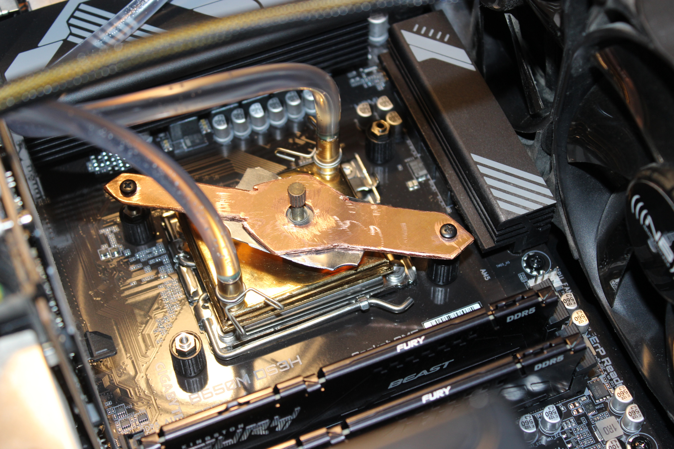
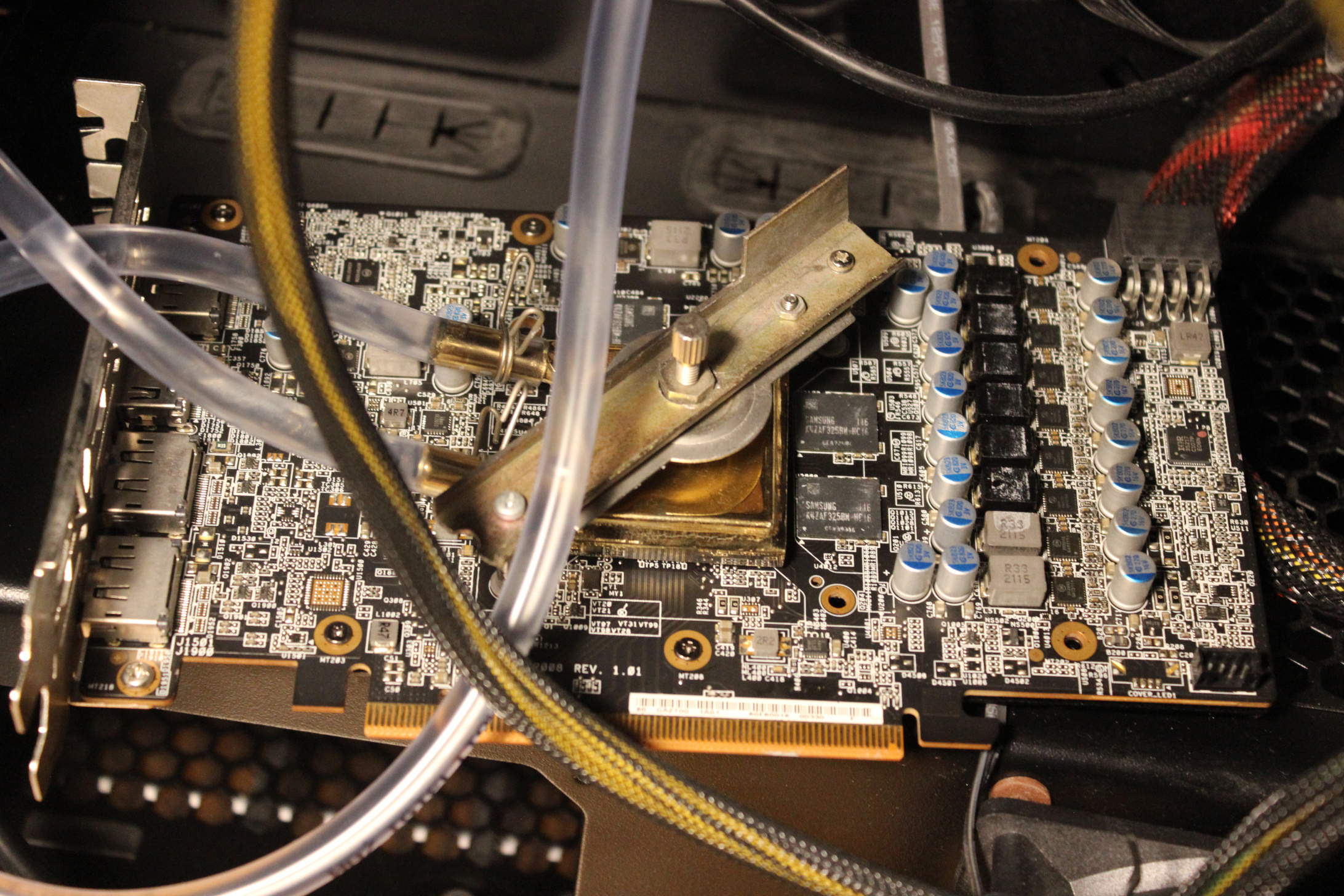
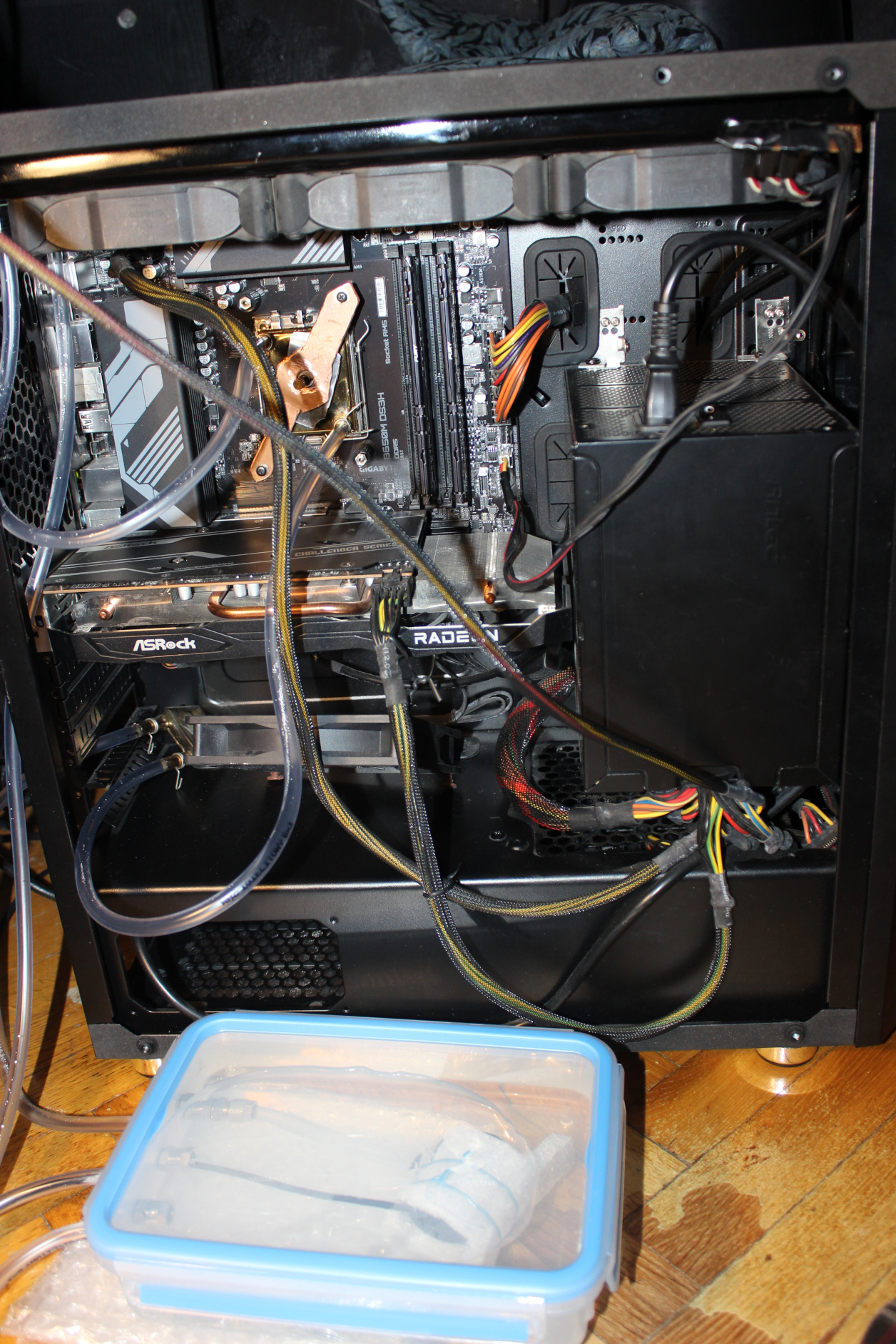
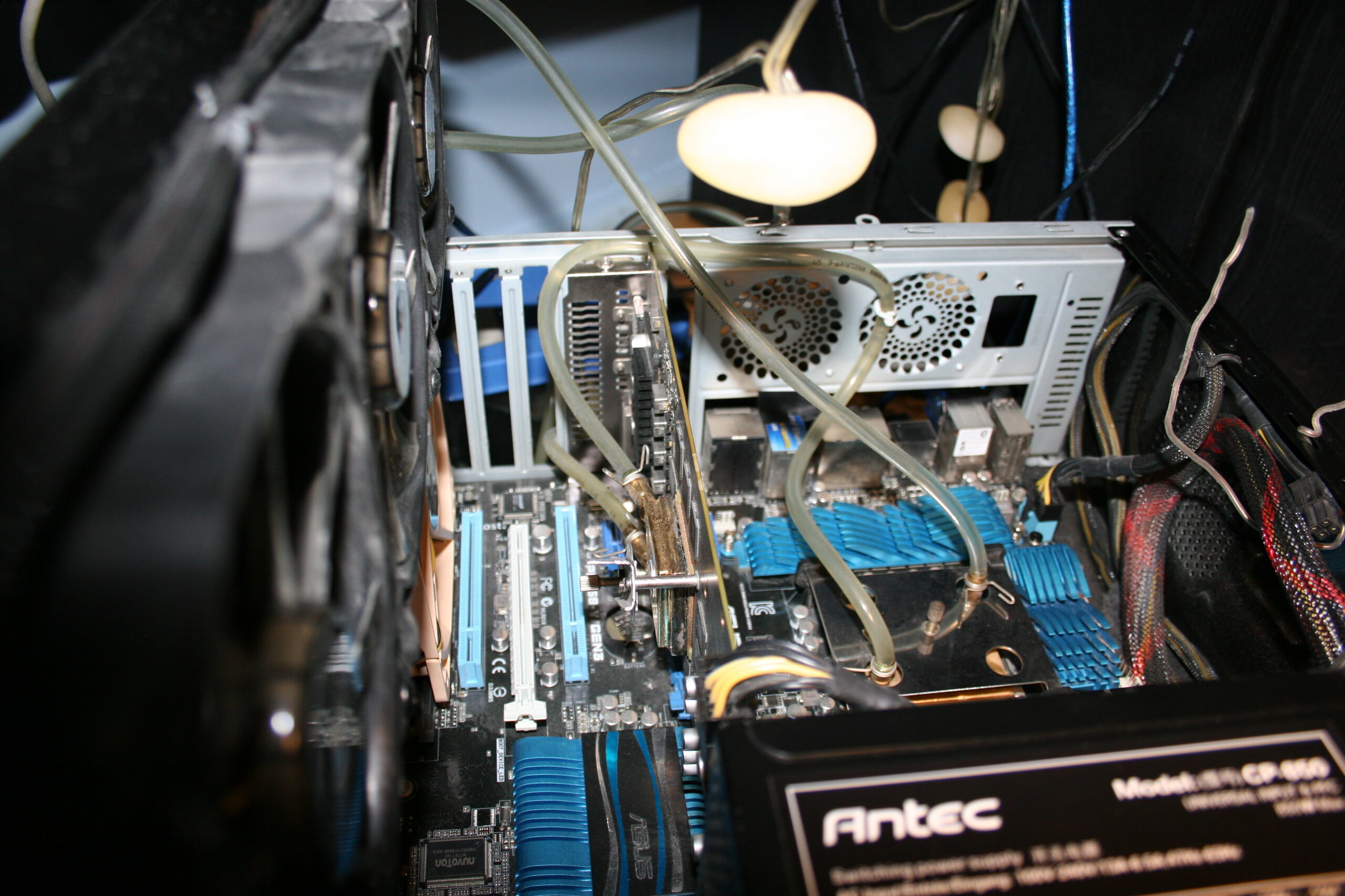
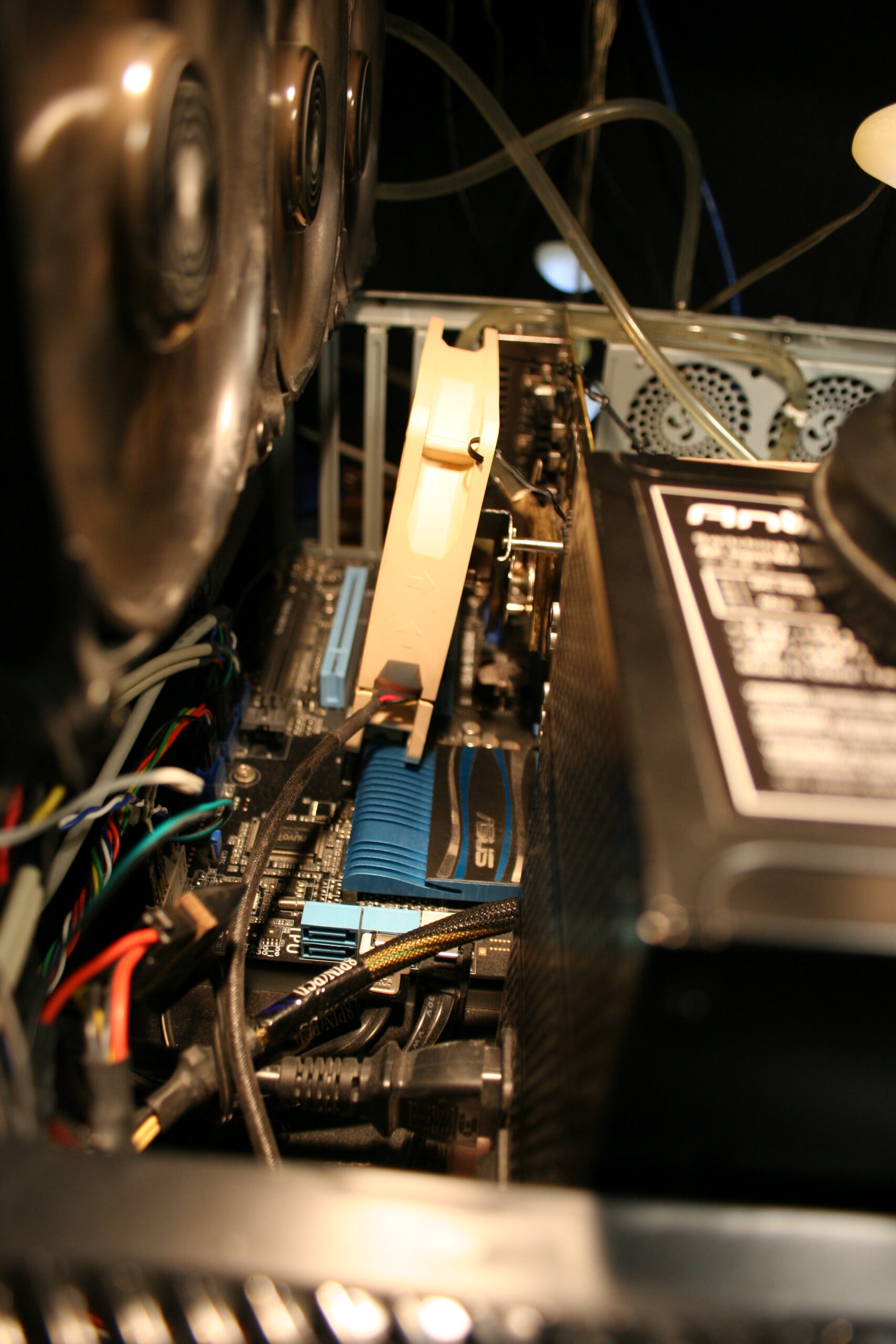
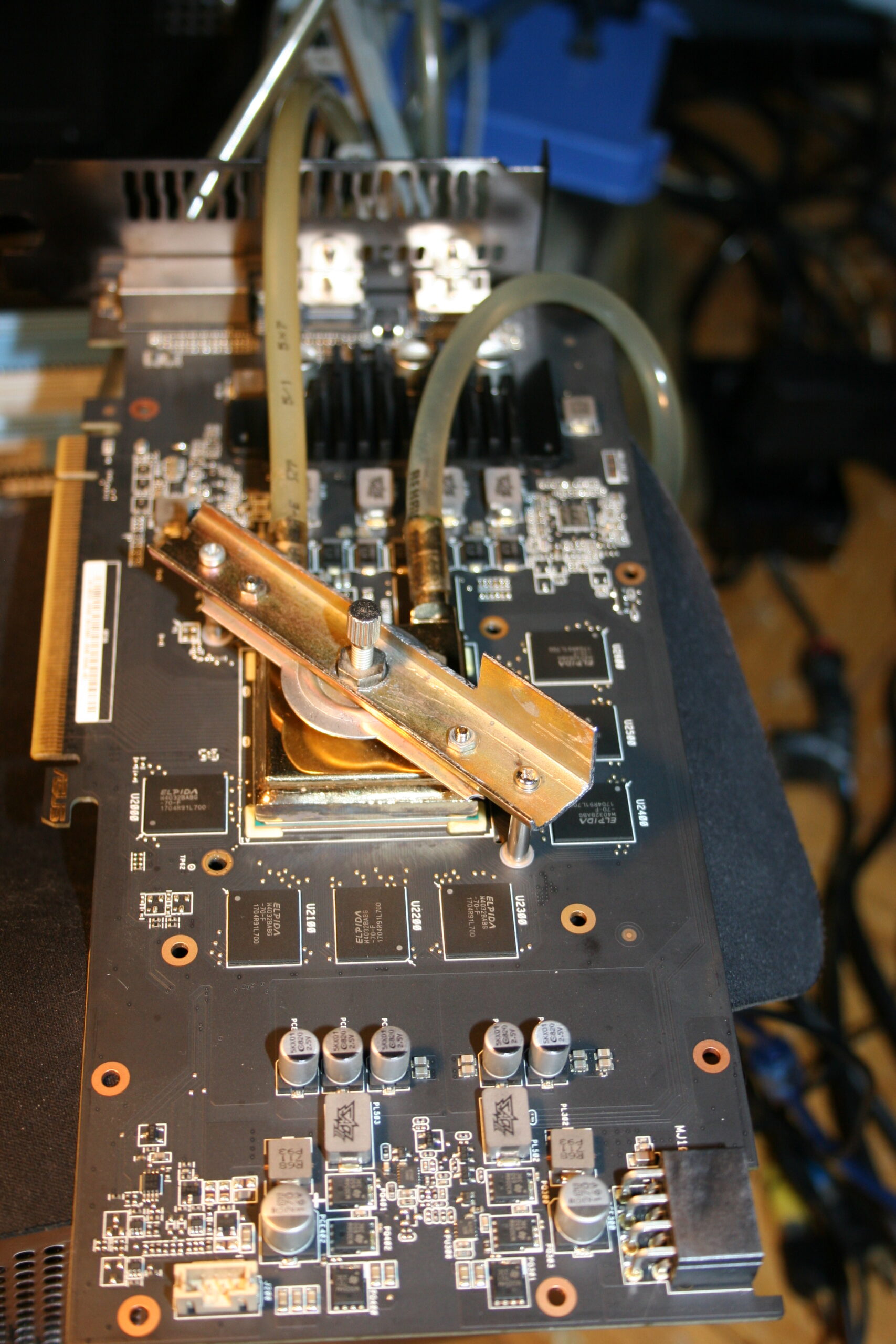
Blocks: old, from 2005 or so, cheap. From a local company, that I think stopped/died after couple of years. These blocks have just 6mm pipes for tube pushed on them, so no expensive fittings needed there. There is a tightening metal around them for extra safety, not really needed, it didn’t leak for me before without them. Mounting (to hold water block onto CPU/GPU) for these water blocks was a bit tricky. I made it myself (DIY way) reusing the old mounting parts. For CPU also cutting an (rough, ugly) shape from copper to match motherboard’s CPU socket dimension and used screws. I think it looks cool, and it screams DIY most (close picture here), on pictures in gallery.
Tubing: has diameter 6mm (1mm wall), to fit those blocks. It is not the thicker tubing used for compressed air push fittings. Also a short 8mm part just out of pump.
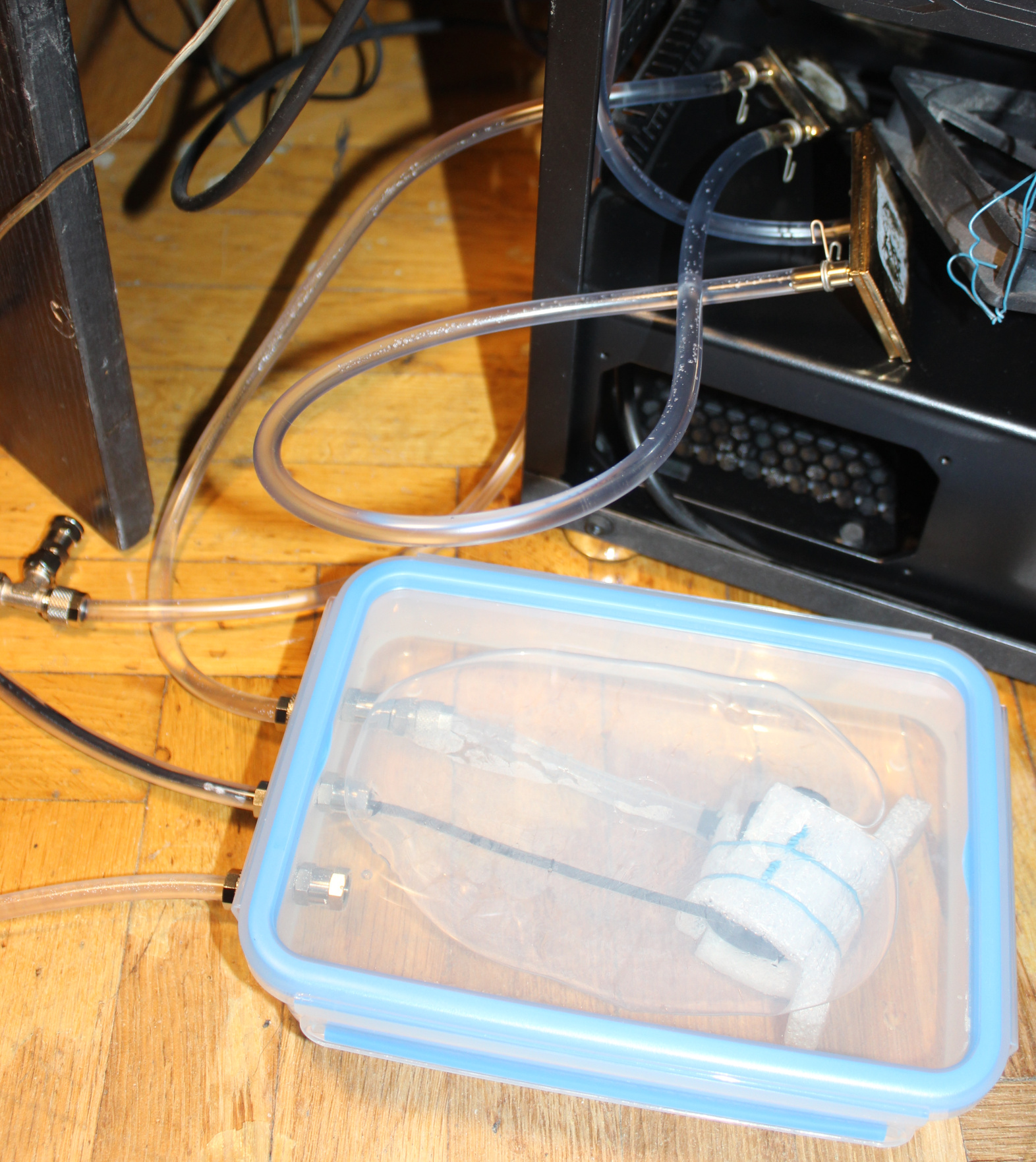
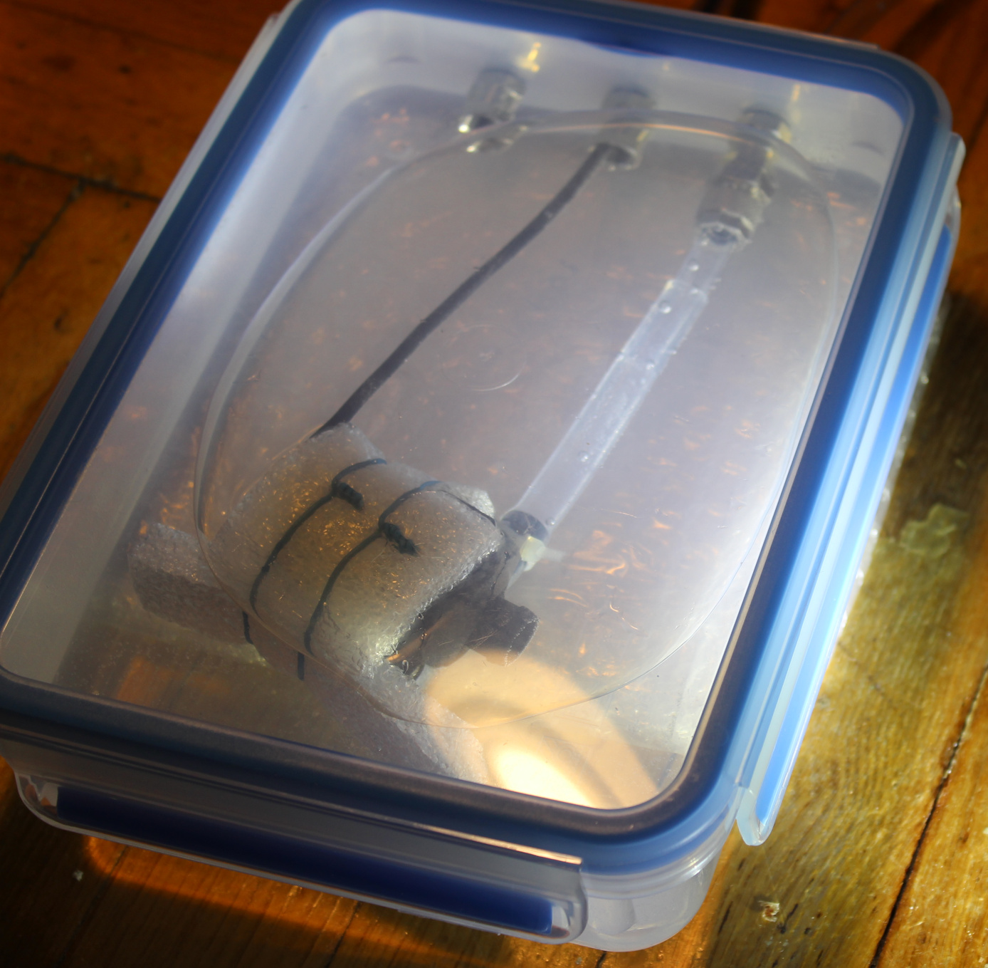
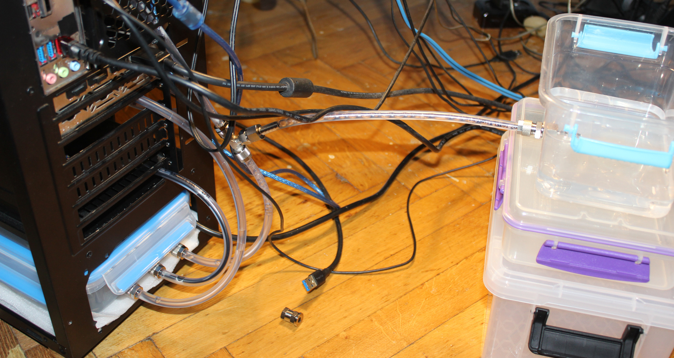
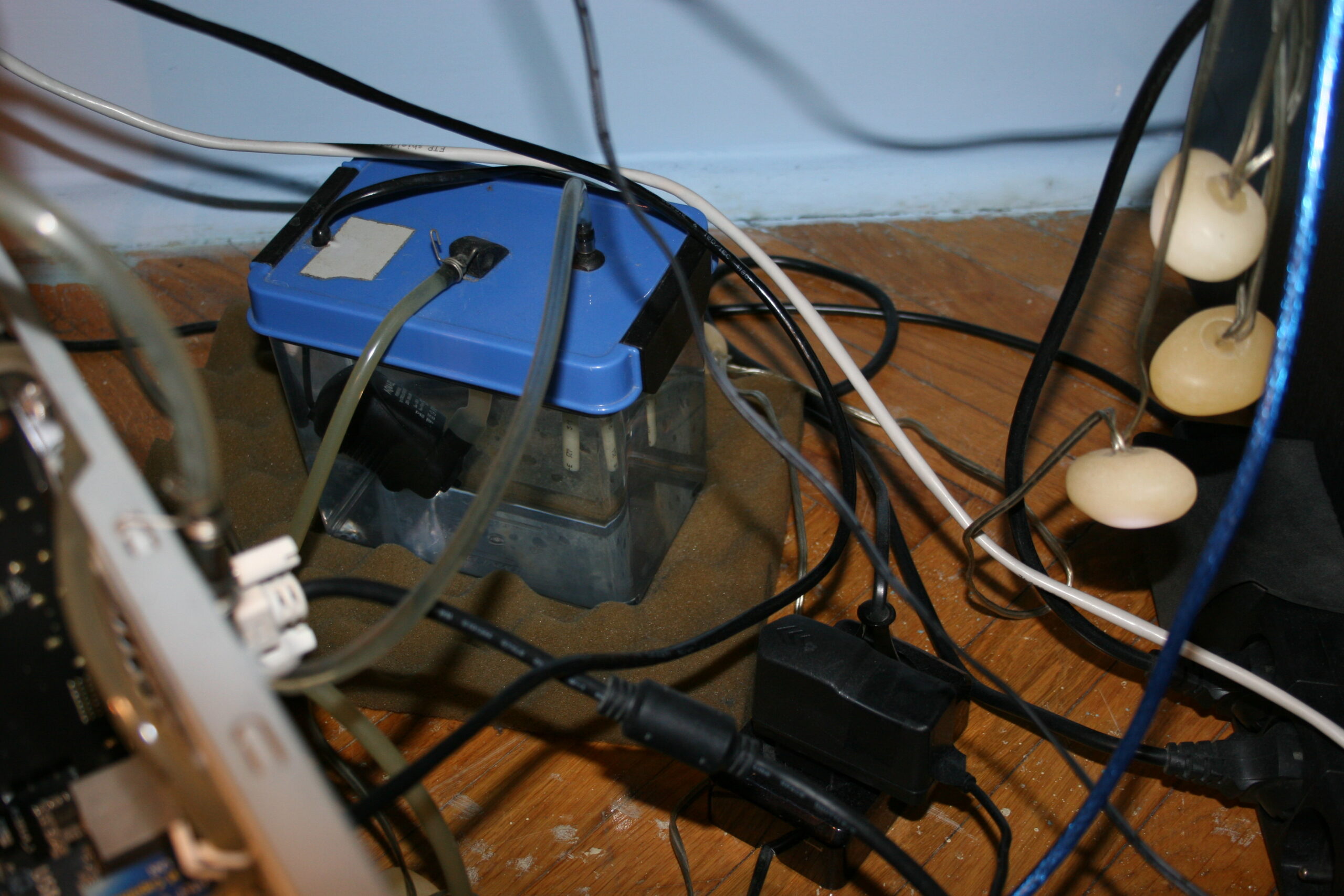
Water tank/box/reservoir. These things are way too expensive (overpriced) to buy. Mine is made from a food container🫙. It gets sealed when closed so water won’t drip out. Rest of it is done by me. I made 3 holes and used fittings (for compressed air or fluids), these have o-ring rubbers for sealing and other side is tightened to tubes. Inside there is water pump, around it I put some packaging foam sheet, held with wire. Outlet from pump has 8mm tube and shortly goes into a 6mm tube, it fit well just like that, by pushing. The 3rd hole (in middle) is for the cable inside short tube. Its end is sealed with just heat glue.
I checked after putting all together and nothing leaked. I added a T-connector fitting, on return way from radiator, closer to ground and water tank. It was useful when filling it with water at first time, from another reservoir (picture). Normally the 3rd connection is closed. A short video of fittings used in my local Polish. And a website showing (nickel plated) brass push on fittings (also called brass rapid joint fittings). These aren’t cheap I’ll add but that’s due to materials and making.
So the flow order is like this: in the tank water gets sucked into pump, then goes outside into firstly GPU block, then CPU block, then into radiator, and lastly returns into tank. This path isn’t very short, but I don’t see this mattering that much. Surely most expensive WC sets use bigger diameter tubes, not 6mm, and shortest distance. it is likely more efficient, but needs a bigger rotor in pump, which I think gets louder.
The whole PC weighs about 11 kg. It surely feels heavy even to move around.
📜All my PCs, history table
Just for reference, last row has components of my current PC (from 2023). The rest of table has nostalgic value for me, but it’s just ancient history. It’s over 30 years since my first PC.
I list all my PCs and main parts so far. Legend for the below table:
? – I’m not sure about exact amount or date 💀 – Dead, it broke by itself. Obviously very undesired. 🔨 – I killed it, so my fault. By bad overclocking @, or by accident otherwise. ♻️ – Sold it, eventually. 🗑️ – It became electronic garbage. ☑️ – Still using it.
Here are water cooling pros (advantages, good) and cons (disadvantages, bad or costly), as compared to the cheaper air cooling:
✅Pros:
Definitely quieter.
Reacts slower to CPU or GPU load (use percentage). As whole water tank heats up slower. Thus it’s nicer, less annoying than hearing high rpm fan every time when load goes higher.
Way more optimal at cooling by water🌊 than by air only. It’s just physics. Heat transfer coefficient for water is between 500 to 10,000 W/(m²K), while for air from 10 to 100 W/(m²K). More coefficients e.g. in table. Of course at end, it still has to be done by air in radiator. But at least that radiator can be of any size and well made for this. Instead of being heavy and mounted with fan(s) above CPU or flat, narrow on GPU to fit.
If done right, it needs less frequent and easier (vacuum) cleaning. CPU radiator (under fan) was always quickly dusty in my case. And it was harder to clean, I had to remove the fan first.
More reusable. I already used these water blocks in 3 PCs. Radiator, previous water tank and pump in 2 PCs. But it did require adjusting or DIY making of new socket mounting to hold water block onto CPU/GPU. Perhaps one can do the same with CPU/GPU radiator and fan sets. I didn’t try making a new socket mounting for that, but I think it’d be more difficult and risky since these radiators are rather heavy and bigger than water blocks.
More place inside PC case, after removing CPU and GPU radiators. Possibly better air flow in PC case.
More room for DIY, more options and more fun assembling yourself. Way more if compared to just default provided cooling.
❌Cons:
More expensive. But not a lot if partly done as DIY, and reused over more PCs for many years. (not that way too expensive crap, made custom for 1 PC or specific 1 GPU, etc).
More components needed: pump, water tank/reservoir, blocks, radiator(s), tubes and their connectors.
There are some full sets with all components and just for cooling CPU. But I’m sure they’re overpriced and I won’t need any.
Likely more fans needed, but they run at low rpm (e.g. 600), thus are still quiet (versus one going high rpm).
Not ideally quiet like with passive cooling or with fans that don’t rotate yet. Because you’ll always need at least pump running which is also usually louder than a slow fan.
More weight, heavier, needs more space.
More risk, after all there is now water here. But I never had any leaks on components, just some water around PC during maintenance like refilling.
With no flow indicator or meter, you don’t know if pump is running. Only by very high CPU temperature shown in OS. This is also risky. A “pc water cooling flow indicator” is rather expensive so I never got one.
⌛Conclusions
I surely waited too long (2.5 years) hearing that CPU fan go loud whenever I started building Stunt Rally 3 or rendering my 3D hammer or even recording with OBS (at just 12% CPU). Well as always when I finish a project I think I should have done it earlier. But it’s a matter of priorities and first doing what’s needed most (or giving most fun😉).
I think I also didn’t do water cooling for long, and forgot I actually am able to, I got experience, and it’s not that risky for me. I never had any water leaked on mainboard or such. I did have some water on floor few times. Meh, used a sponge and towel and that’s it. Even this time, when filling, I think I had too much pressure and the tank started leaking on floor. BTW I was on phone when it happened, which was stupid too.
For me it was always way too annoying to hear a CPU fan over 1200 rpm or more. Especially every time CPU load goes high and fan goes loud. The solution is water cooling, it’s a different approach, also one that’s much more optimal by physics. If I don’t increase fans rpm accordingly, then water will get more warm, but slowly. Eventually I have to cool it more. But it’s my choice.
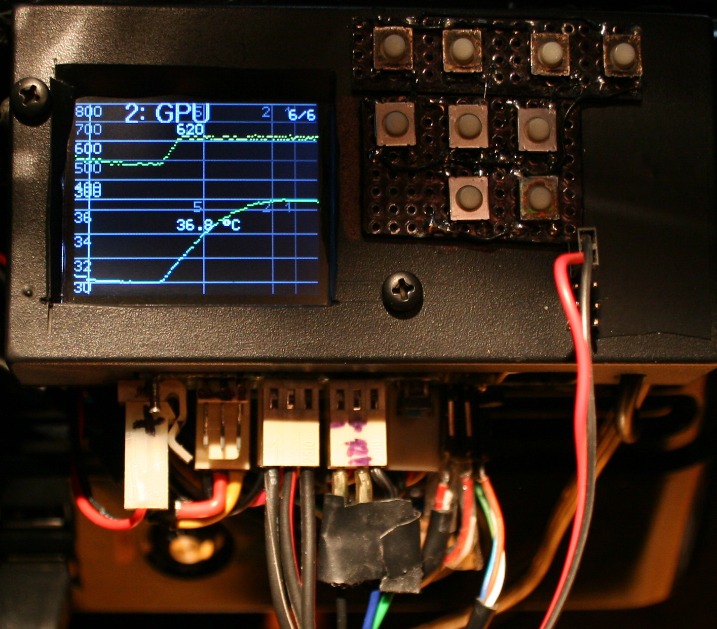
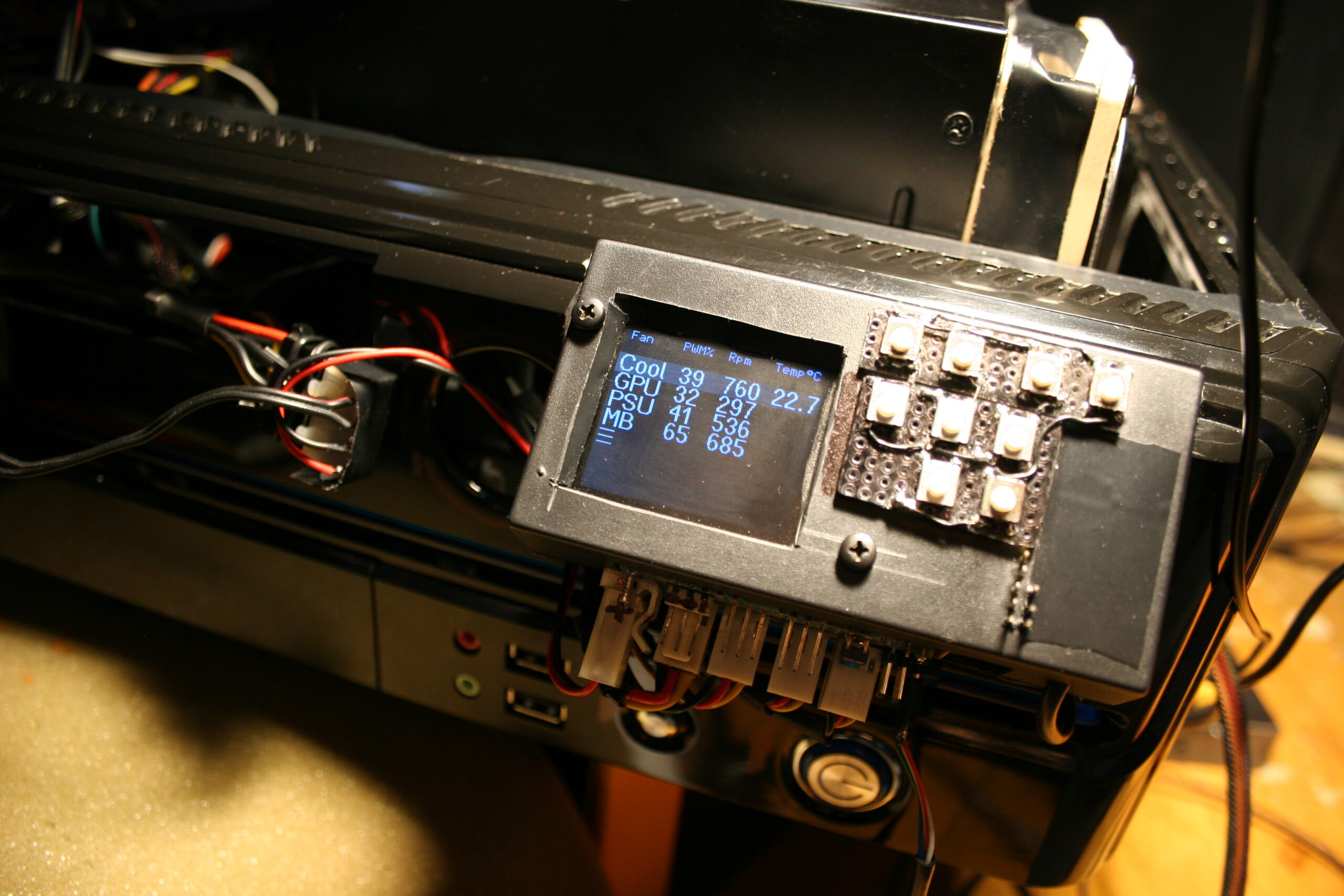
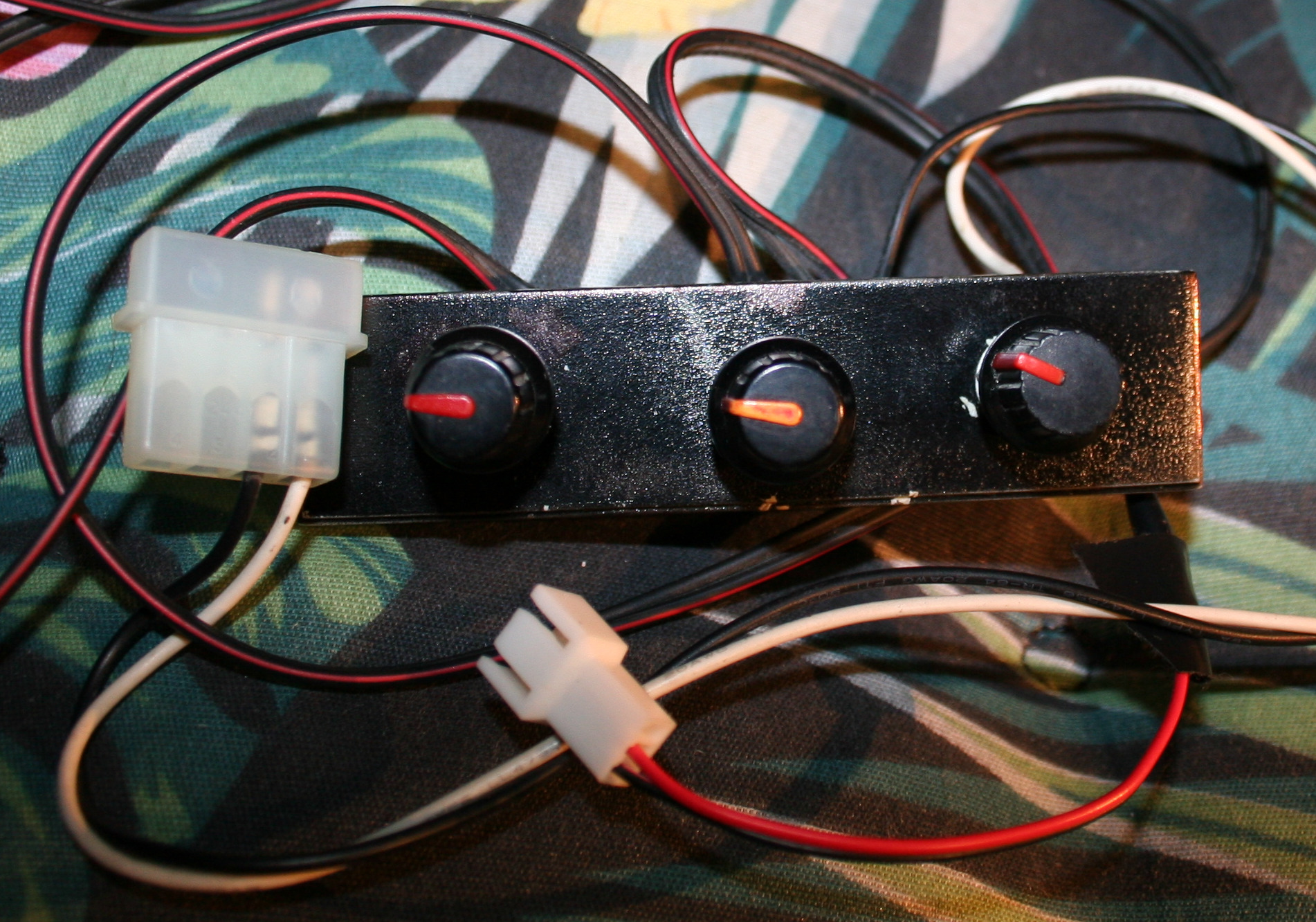
For now I have only 2 manual knobs🎛️ for both pump voltage (flow, speed) and radiator fans (rpm). Both when higher get louder. For pump it’s about making it quietest and still running, since (in my experience) making more flow doesn’t help much, it’s just loud. The key regulation is for fans on radiator. These can be quiet when CPU isn’t doing much, and have to eventually be a bit louder when CPU % use goes high for longer.
Possibly my WC could use a custom (auto) regulator now. I mean I can’t just add a water temperature🌡️ sensor(s) (e.g. DS18B20) to mainboard, and use its software to auto regulate pump’s (not really needed) or radiator fans’ voltage (rpm). It was possible with just air cooling. And since I got new PC, its mainboard could do that. Thus I later disassembled my fan controller (I used its MCU for other project). But it’s for me another reason to remake my fan controller again and BTW adapt it to other MCU (cheaper Esp32 now).
Lastly I do rarely look at those fancy (and stupidly commercial) water cooling PC cases, with unnecessary, expensive style, RGB LEDs and whatnot. I despise all that. For me a PC is not about looks or light at all, it’s about: functionality, DIY solutions (as nobody makes what I need besides me, e.g. my keyboard firmware), reusability, and minimizing costs (stretched over many years).
📷Gallery
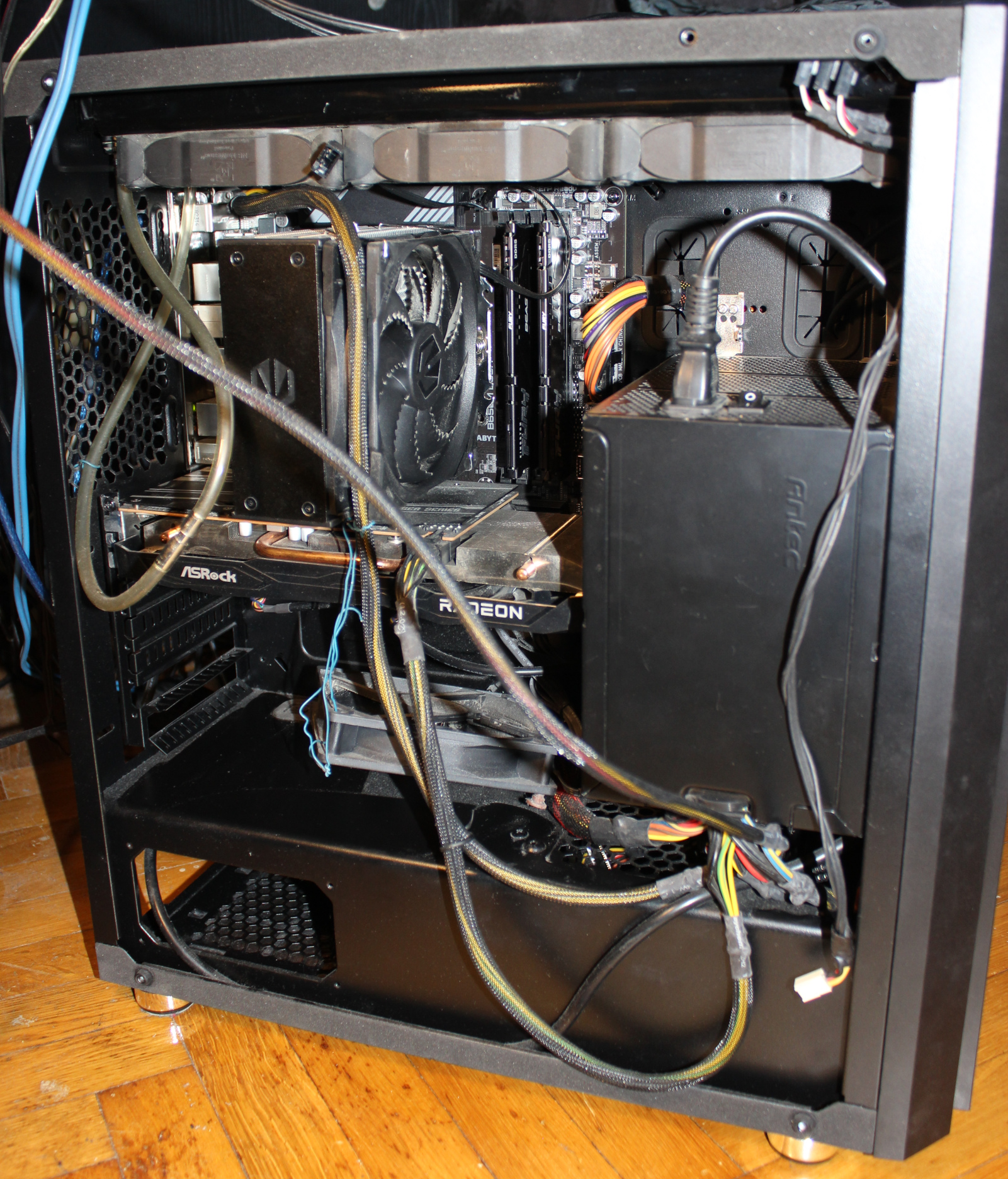
Starting with good whole PC pictures, some close ups on blocks (CPU and GPU), then DIY water tank/box with pump and last 2 screens show the old air only cooling. Yeah, surely the floor is old and ugly, has been since decades.
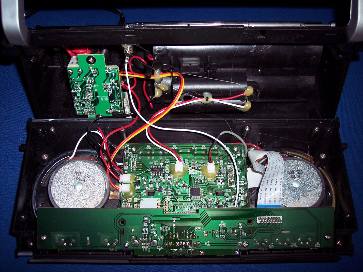
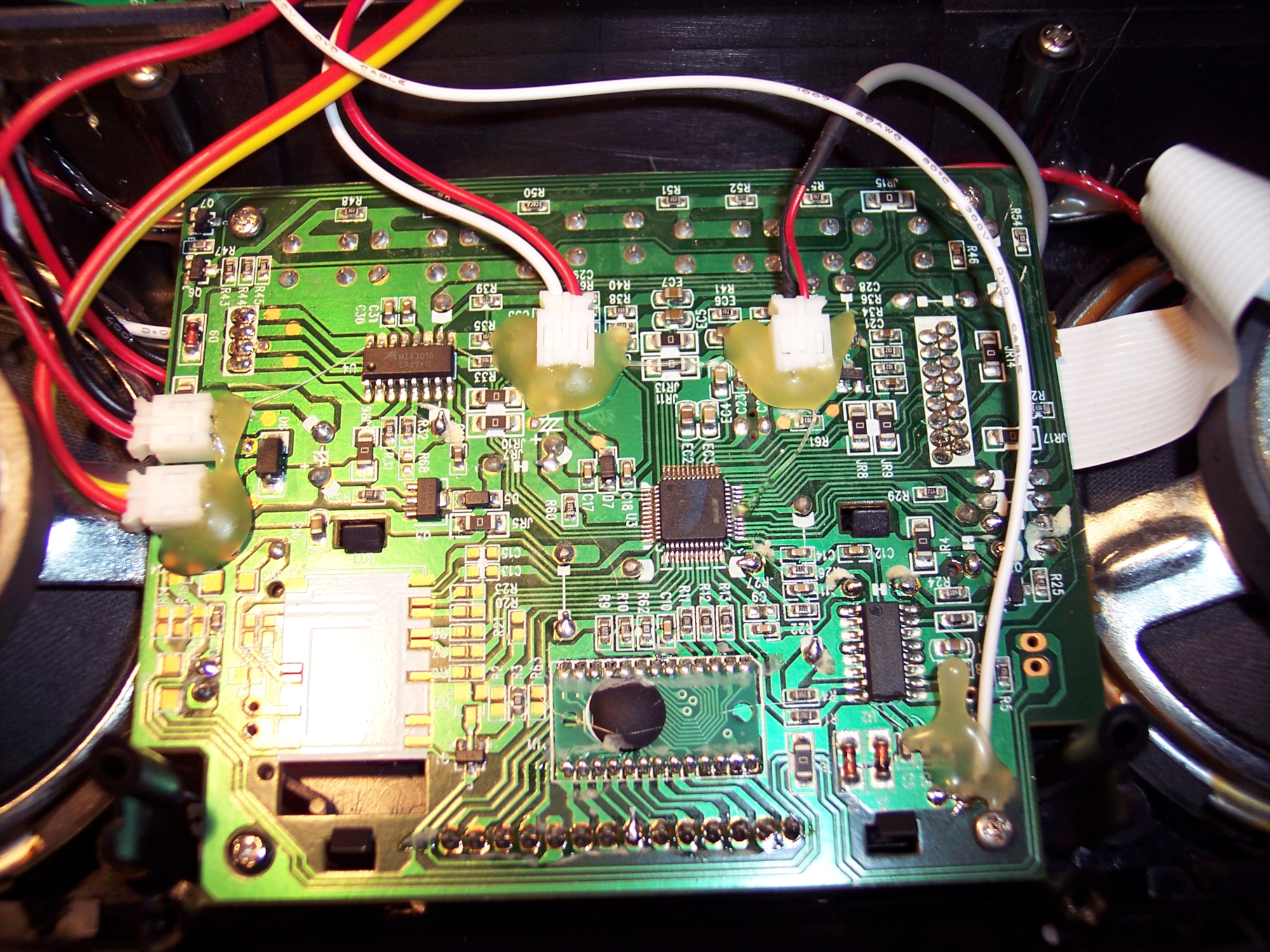
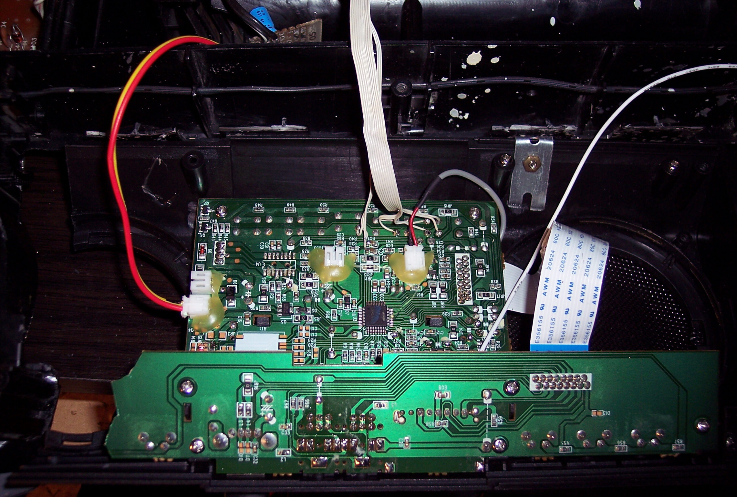
This is a continuation of my previous kitchen HiFi modding. Now with replaced electronics for power supply, amplifier and input selectors. Only radio and case stayed the same. So roughly half is made by me.
✍️Motivation
Previously there was here an ancient old power amp chip LA4108, from around 1995 or so when this HiFi was build, with 2 cassette decks. This amp was way too powerful and not quality enough for our times. Since I didn’t need much power, I just remade it with a very simple op amp amplifier, feeding speakers. I also wanted a holder to put my old audio player in place instead of just lying flat and hardly seeing its LCD. Lastly my mother found it hard to see what to press for radio and lost the volume knob behind our kitchen stuff since I moved it on side.
📊Features
Op-amp amplifier feeding 2.7 Ω speakers through 47 Ω resistors. I still had OP275 lying around since like 2002 so I used it. Well it could be NE5532 or anything really. I didn’t bother with any transistors (class AB or A) at all to boost current or more power op-amps, because it was enough and we don’t need to hear it too loud 🔉🤫.
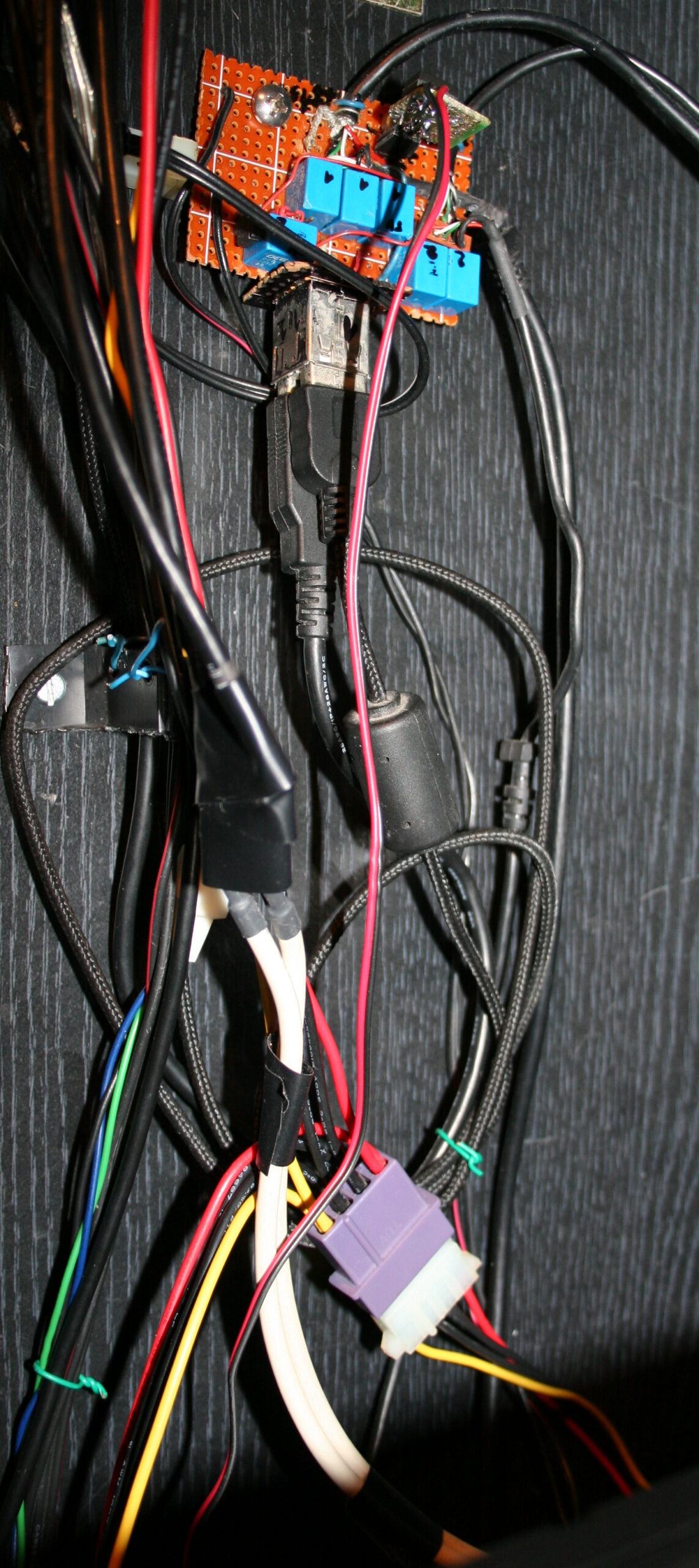
Selecting 1 of 3 audio inputs from: FM radio, player (Sansa Fuze+ with Rockbox firmware), and external audio cable (going from my room to kitchen, analog but through Ethernet cable). This is done using a MCU (worst for today Teensy 2.0, only because I have bought it long ago when I started and wanted to use it for any purpose finally, it’s ancient 8bit and 5V too, while I moved to 3.3V in my keyboards and all). Code was like just 50 lines, 3 buttons, 2 outputs for old 12V stereo relays, and 3 outputs for LEDs to show which input is selected to play.
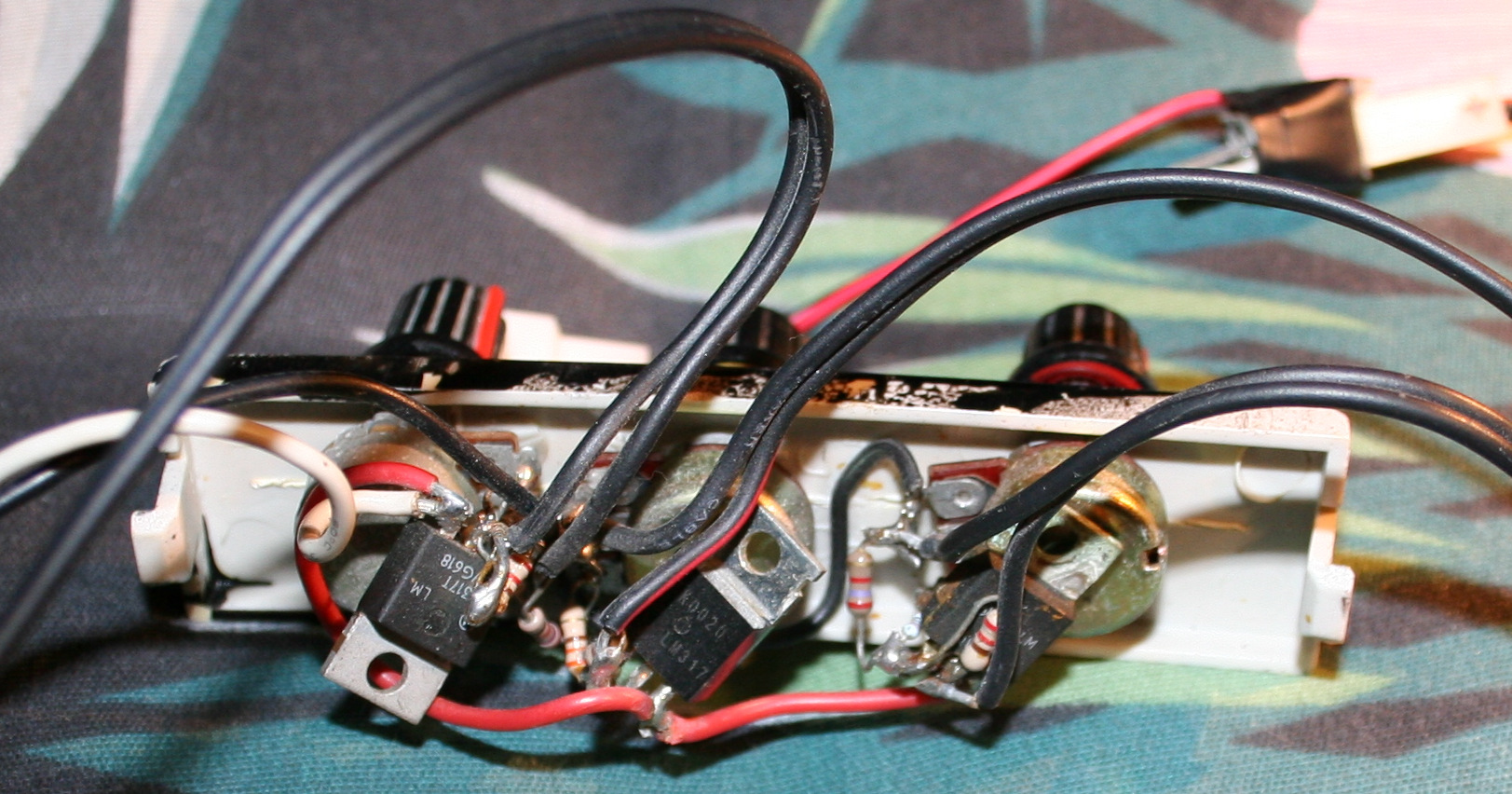
Power supply for player 4.1V not from battery anymore, slightly with noise due to this. Op amp uses +-16 V from 2 regulators LM317 and LM337 from a 15W transformer (could be less, but it’s what I got since years waiting, not used). Another with 12V for relays, and 5V for MCU. So yeah kind of nuts 5 voltage regulators here. It’s likely the reason it takes 3.5W from 220V wall, already doing nothing and about 5W doing something.
⌛Conclusions
Well half of my conclusions are already in my previous project for this HiFi back there. I.e. no reason at all to buy new stuff, better to modify this over 20 year old classic, especially after I painted it so funny. It was also working so best to extend it further and make it better for me.
So far I can say it is a joy to use and really good audio quality for me. I didn’t hear any noise, especially not like before. I hope it will last for few years at least, until I come up with something new I’d like to add. Or possibly get my stuff from inside and use new speakers, who knows.
One definite down side is that it took me about 5 days of holiday to do this, so it was way more than I’d like and lots of work still.
Another bad thing is that it uses 4 W power constantly, likely just because of so many voltage regulators here. I didn’t complain about this, since I got more power lost in stuff that’s constantly on in the house all the time.
But this also, eventually motivated me to rework it once again in recent project from 2026.
I described here my old PC and its Water Cooling (WC). Newest is here. It also features my own fan controller, which motivated me to finally create this page. Obviously, I’m using my own firmware in heavily modded keyboard with my PCs.
💧Water cooling history and observations
History intro
I got my first PC in 1992, as seen in my very first post here. I had many more since then. I’ve put my full PC history in last chapter, at bottom.
Until 2004 I had no big issues with PCs and their noise. Those had 2 medium fans (about 9cm), one on CPU other in PSU. Surely those weren’t quiet (just cheap) and were mounted firmly so their vibrations were even amplified.
Before WC
In 2004 I bought a new Pentium 4 and decided that I had enough of that noise, “a PC should not be heard” I said. So I first started buying “quiet” fans:
Well the small 9cm: Zalman CNPS7000A-Cu wasn’t that great, was full copper (whatever, too heavy), and with so little space between fins it was great at gathering a lot of dust, but it had a nice knob regulator.
Years later I found a good one: Scythe Grand Kama Cross 2 for next CPU. It’s big but not very heavy, and has a 14cm fan which actually makes it way quieter. It’s still used in my mother’s PC.
Well that was rather a waste of money. Not very expensive, but not very quiet either. Yes until now, I’ve spent much more for WC in total, but it was used in 3 PCs already. I’d even say it was more universal than those “quiet” PC fans dedicated to some socket or one GPU type only.
WC Kit
I bought a WC (not to confuse with 🚾🚽) kit from a local company Cpc/Hydrox. Needless to say they changed company name like 3 times, didn’t last long etc. But sometimes their parts still appear on auctions. I even sold my surplus once this way. To put it short, their cooler was crap, their WC PSU plain garbage (cheapest and also had a loud fan), water pump was just a cheapo for aquarium. So a kit was really a bad way. But water blocks were cheap and very good.
My PC evolved the most since 2004, when I bought that Pentium 4 and started water cooling it. My current PC still has most of the WC parts from that time (water blocks, 6mm (~1/4″) tubes, water reservoir and pump).
My choice for that kit and 6mm was its low price. Seriously, whenever I tried looking at other water blocks after (thinking I could maybe improve mine), all were 10 or 12mm (~1/2″) diameter and literally 3x more expensive.
PC WC Modding Rant
Back then, once a while, I was looking at pics of modded water cooled PCs, with “style” and plenty of lights too. How do I put it, just IMO OFC, let’s just say that’s the most illogical (retarded) thing to do with a PC. It’s the same approach as in modding cars. It’s a huge profiting business, a hype and really nothing more IMHO. Apart from water cooling, which is the most logical way of cooling, but for PCs it is way overpriced. Modded PCs are the culmination of commercial stupidity, visible from a distance and eye catching (i.e. self promotion).
For me it was a matter of how loud my PC still is, best measured in acoustic dB. Just like I said: “a PC should not be heard”, I also add: “and should not emit any light” or otherwise be visible even. Of course, since my PC is on floor under own desk, I do have some white lights to make it visible when needed.
And it also mattered a lot more for me to have other modifications. as described in next chapter.
Radiator
I changed the radiator from kit, to a decent (got it used) copper for one 12cm fan. It was too small as it turned out. Water was heating up, fan didn’t manage to cool it when CPU was at maximum. At some point I had two such one fan coolers. I think it still wasn’t enough, definitely not for CPU and GPU, and too much tubing trouble. So at that point I bought a 3 fan radiator Black ICE GT Stealth 360 and I’m still using it today. It isn’t very deep and it’s easy to vacuum clean the dust from it. I do this like once in 6 months.
After moving my PC to WC (water cooling, right), I surely hated every CPU stock fan, especially those loud, stupid, cheapest Intel vibrating fans. I once even just cut off that fan of radiator and mounted a quiet Noctua 9cm fan above it, this worked well and was way quieter.
Fans
At some point I searched for quietest fans. After I think 4 tries I settled for Noctua. It actually varies from model to model. And the downside is they are ugly, have distinct color, which I didn’t spray black, to not risk damage.
For the radiator I bought 3 Noiseblocker fans (to be cheaper than Noctua and black already). They also have those rubbers good for mounting on radiator. I’d say they’re okay at low RPM, but not when higher, I can hear some motor noise.
HDD
Naturally after having CPU and GPU water cooled and quiet, the next thing is PSU and HDD.
HDD is easier. I used to wrap it in cloth, but this makes them too hot. So now I have one in some foam, covered by some old noise reduction foam, with the back being open to air.
PSU
I did try 2 noiseless fanless PSUs in 2004 or 5:
Yesico FL-550ATX, a heavy tank (big parts) that was always hot, but quiet
and Seasonic X-460FL, a light empty, too expensive, low power PSU, that wasn’t 0dB quiet, it had some high frequency hiss noise.
After Pentium 4 for better GPUs, I needed more power but there were no such fanless PSUs. I made a very stupid thing and tried using both fanless PSUs in 1 PC. Just connected their grounds and I killed Yesico this way?☠️.
Finally, some time later I found an awesome PSU: Antec CP-850. I even bought a 2nd one for my other PC, a year after. It is bigger then most though. Inside, it wasn’t freaking all cramped to still fit the old retarded dimensions from very first PC ATX PSUs. It is just stupid: airflow is chaotic, no space left, all big hot inductors are nearby big capacitors (which don’t like heat) etc.
Bigger PSU is spacious inside and its design with components in lines is good for airflow, thus the 12cm fan is rotating very slow. BTW I eventually replaced it to a quieter one. There is a big surplus of power 850W, I’m probably using 130W to 300W. So it won’t heat up and suffer from it and/or make noise.
Case
Yes the Antec PSU is bigger and won’t fit most PC cases, at the time there were only 3 available for it, but that was just a stupid commercial for their products. PC cases are likely my last concern and I buy them as rarely as possible. I used this PSU outside of my PC case from 2008 for 15 years now. My other PC has it on top. Eventually I moved to even smaller PC case and I placed it inside, thus making it look like it does now, sticking out.
🛠️Modifications
Apart from water cooling things, I have many utility mods for (or in) my PC:
external relay 220V to power water pump, and DAC (earlier audio amplifier) when PC is on
for years I had just a simple analog knobs for PC fans, now I have my own fan controller
2 USB switch I use it to switch my keyboard and mouse between my PC and a laptop. Works like a charm, I can’t imagine not having this now. I did it on a universal PCB with relays, since I had them available, but they do use 2,5W when on. There are 2 USB input ports and 4 output USB cables: one pair to PC and other to laptop. There are 6 relays, for 5V, D+, D-, and GND is common.
external switch for monitor input, near keyboard This was a bit tricky. I had to disassemble my decent LCD monitor, get to the switch, solder some wires, and add a long 2m cable with external switch. It is extremely useful, I don’t have to lean to press and wait like that too.
📜All my PCs, history table
I list all my PCs and parts so far. Yeah, it’s over 30 years since my first PC. This chapter is very optional, since it has quite nostalgic value for me, but otherwise it’s just mostly (ancient) history.
Legend for the below table:
? – I’m not sure about exact amount or date 💀 – Dead, it broke by itself. Obviously very undesired. 🔨 – I killed it, so my fault. By bad overclocking @, or by accident otherwise. ♻️ – Sold it, eventually. 🗑️ – It became electronic garbage. ☑️ – Still using it.
As a kid I didn’t have new PCs too often, they were also getting faster and obsolete quite often. Then after a brief period of having newer hardware (mostly GPUs) somewhat often, while most of them died too early I think I realized it’s not good to buy (they’re soon to be garbage anyway).
Later I realized that since years CPUs don’t really get much better, yet they do cost same or more. Thus my CPU and MB is still from 2012 (happy 10 years man). I did have them overclocked for few years, but now I even don’t. It gets 30% faster, but uses 30% more power. So I’d rather have 100W (not 130W) at idle, when I just listen to music or watch something. I don’t need that extra 30% like I did when I was building C++ often, for Stunt Rally.
After all PCs are just tools (and not just gaming like consoles) but for learning, creating and entertainment too. So naturally buying a PC is an investment, that has to be done rationally.
Some time later I decided it will be better to buy (instead of new PC) a new ergonomic chair (for PC) and a bed. Those are similar priced but much better for health.
➡️End
Well in Sep 2023 I bought a new PC, even with case, only PSU still same. Added it to history table. It feels way faster than my previous, like 3 to 5 times. It seems I’ve skipped a new PC (CPU+MB) somewhere along the last 11 years. I always aimed for new PC to be at least 2 times faster to not waste money and time for updating. It needs some time to update, like a week to choose right components, move OS setup, etc. I cleaned dust in this now old PC and moved to air cooling again, then set it up and gave to my mother. Replacing previous one, which was way too slow, nowadays even movies were not smooth. Yet still almost all PCs of mine drain above 100W at idle. Well it’s good to update and do stuff faster, but of course still a high cost to get new technologies. I did move to water cooling with my new PC too, just a couple of years later in 2026.
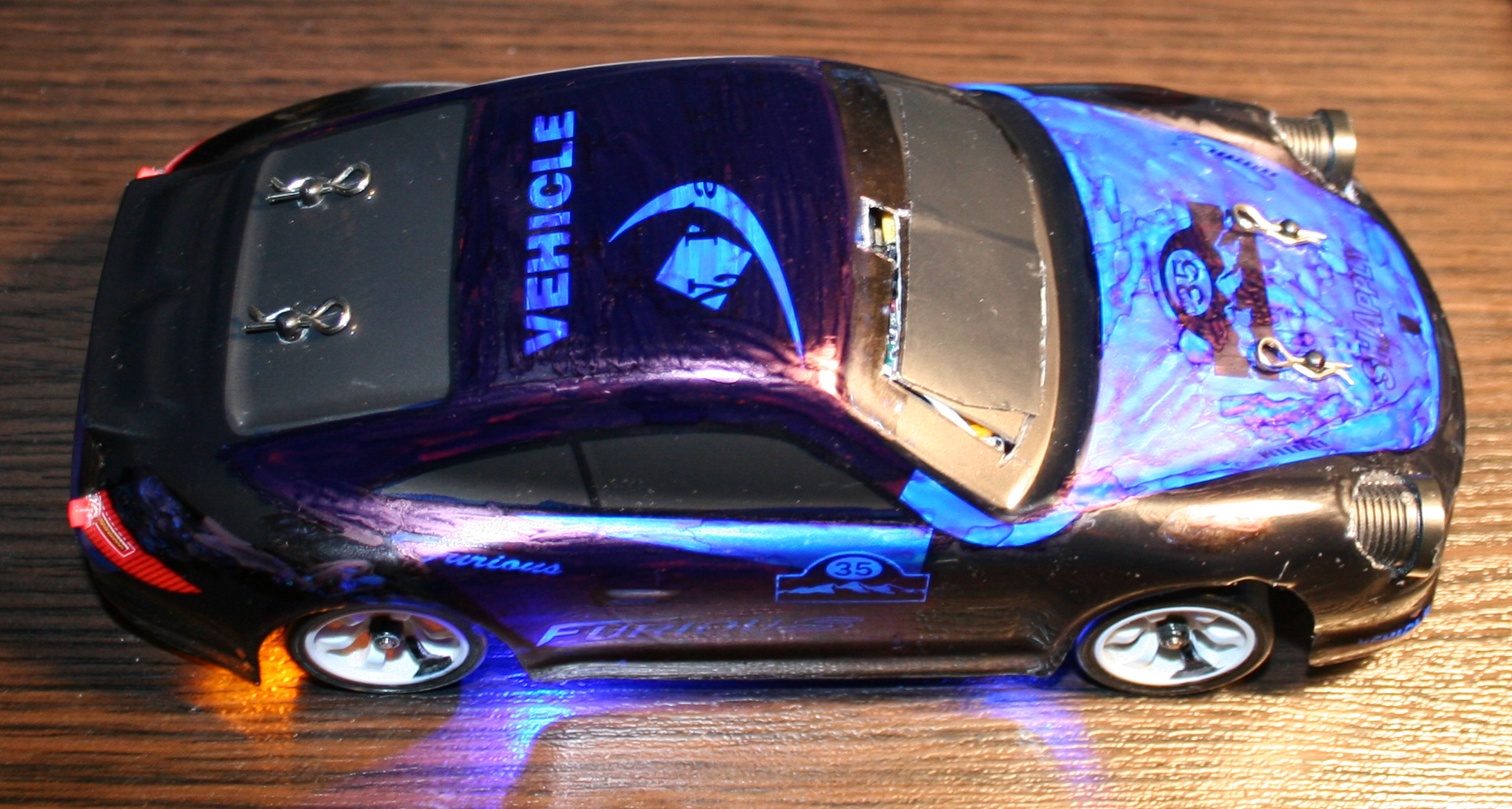
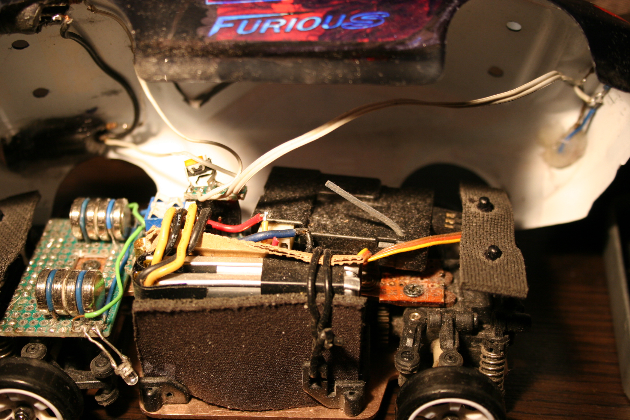
At end of 2021 I bought a WLtoys K969 RC drift car. I will describe here all the modifications I made to it. Also with few review remarks about it, less important comments and rants are italic.
▶️Video
Video here. Drifting in empty office on carpet and kitchen floor (best of montage). Camera was just from old phone: LG K10 2017 Car camera: Ion Snapcam LE, like mentioned below Software used to for video editing: Kdenlive on Debian GNU/Linux with KDE Picture gallery at end of page.
📜History
I guess I should write this chapter here, since being almost 40 requires (an attempt for) an explanation🙂. Well, as a child I only had a few (probably Russian) cars from 80s, Two did have a cable from controller, and the one that was radio controlled had only 1 button to go backward, which also made it turn. Yeah I also can’t even. As a teenager, at some point I got an RC car. It had rear wheel drive and used 27MHz. I think I drove it only 2 times. It was fast and meant to drive outside. It had rubber tires so it stuck to asphalt and would rather flip over instead of sliding. It seemed kind of hopeless (compared to today RC toys) and felt like something is missing.
✍️Motivation
In the mean time I got interested in WRC and 4WD on gravel, played a couple of such games too. And finally made my own Stunt Rally. There was a time when I was a lot interested in tires and car simulation.
Recently, once a while I was watching various videos about RC toys. Technology moved forwards a lot in them too. This way, I found out about RC drift cars of 1:28 scale, and after days of watching videos and researching what would be cheap, but still good for drifting at home (or office) I found this WLtoys K969 and saw how it drifts at home. I think I watched later other 1:28 cars (like Mini-Z, Mini-Q etc.), and realized that even thought they are much more expensive they aren’t much better. At least for me as a first car, I don’t intend to drive RC professionally or on tracks. There are also cars and people who prefer RWD only drifting (front wheels move freely), but I was never a fan of that.
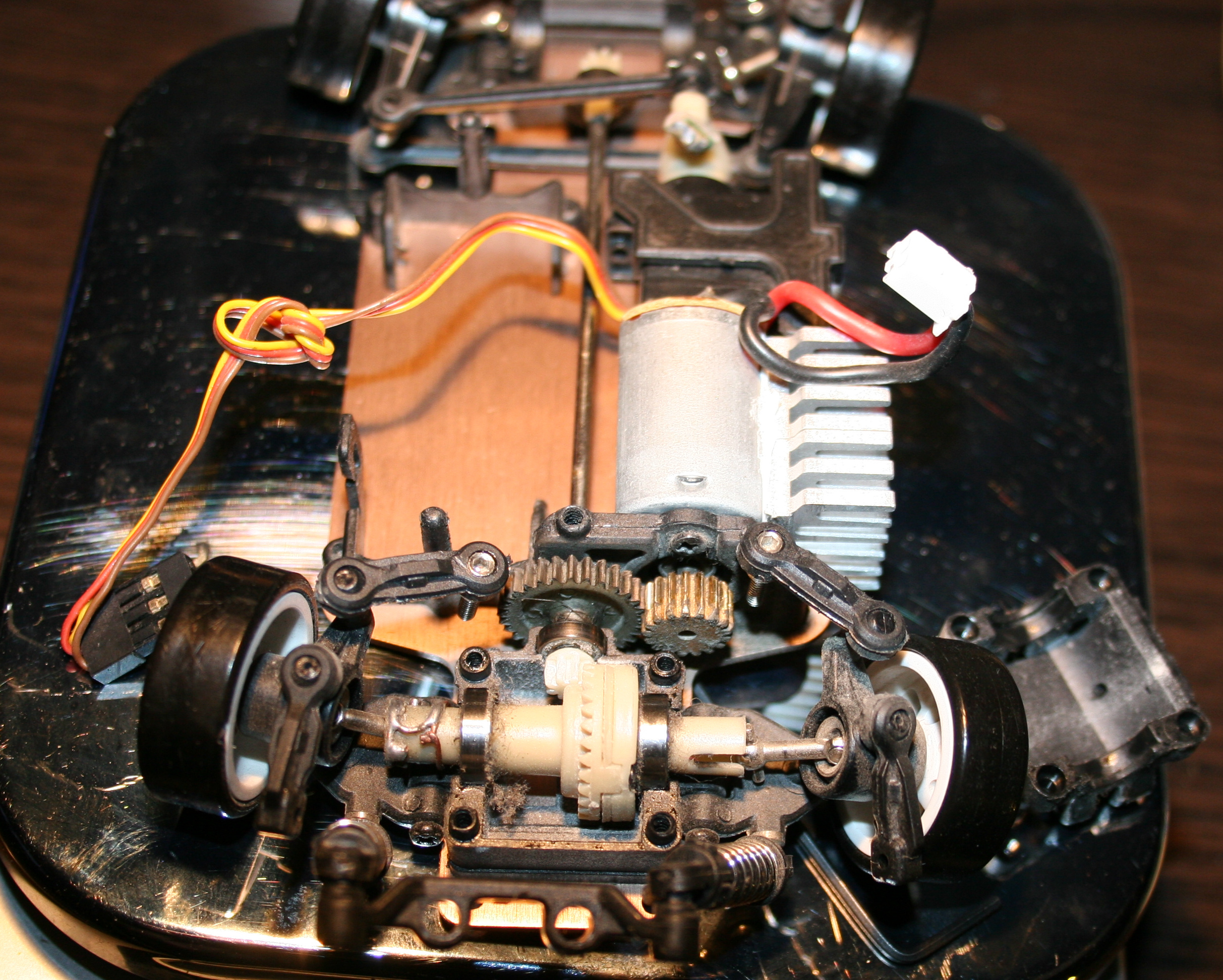
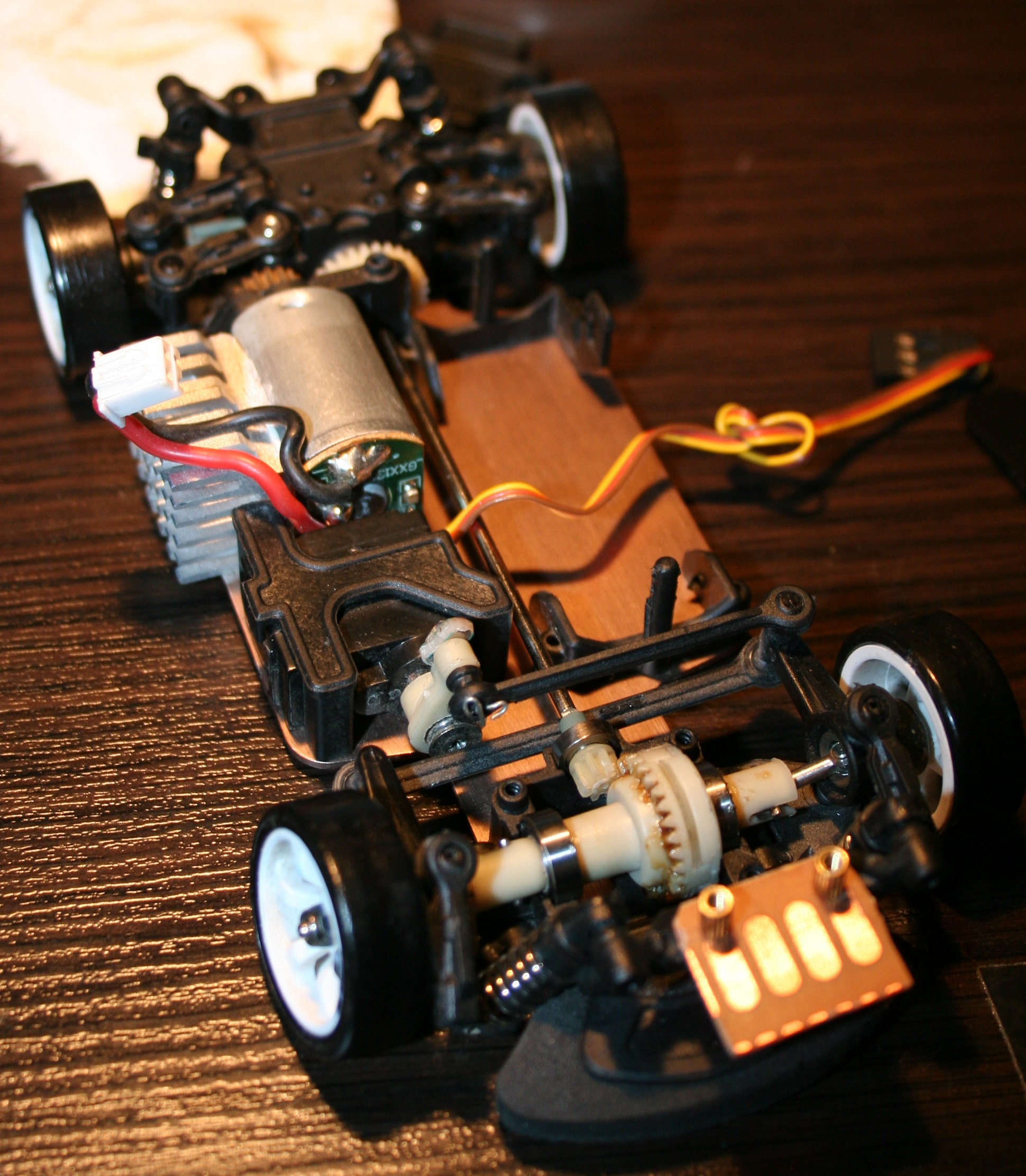
So I think this RC is a nice, real life example, even if in smaller scale. It surely reacts and changes direction much faster than real cars. But is certainly less complicated, has no: LSDiffs, torque curve, gearbox, central differential, etc. In this RC all wheels rotate the same, electric motors don’t even need gearbox, suspension has only stiff springs, and there is no flexibility in tires, since those are from hard plastic here.
🛠️Modifications
So the things that I changed and added first to last are as follows:
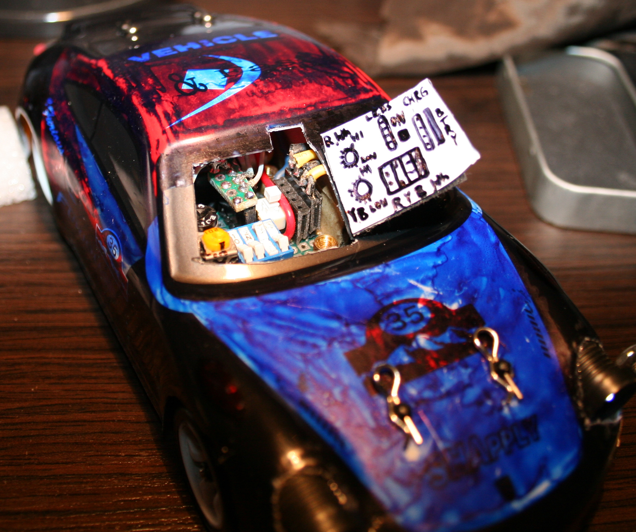
Moved the pin from servo‘s steering arm higher for more steering angle range. There is a video here where it was easy.. But, a huge but here, as it turned out (for me) the upper hole for this screw is wider and I couldn’t just simply use the same screw from lower hole. Thus I had to go creative to achieve this. Since I soldered a lot, I came out with a solution of putting few wires together for right diameter, then soldering one end to a tiny PCB part (with 1 hole), and just bending 2 wires out of the other end. It still holds well. Visible on my last picture. I guess this isn’t that important but is very good to have. Without this, steering angle is lower, making wider turns, but you still can make tight turns by drifting with quickly spinning wheels to oversteer (lose grip on car rear).
Made throttle range adjustable. How to video here. BTW I recommend that channel, it has many good videos including for this RC car. This is actually the most important one. Without this it will be difficult to not spin out wheels all the time. For small rooms, throttle range needs to be even lower. Of course they made the car to be cheapest, and even didn’t add the most important adjustment to it, I didn’t need those side buttons, so why not having this instead. Meh, always have to make things usable myself.
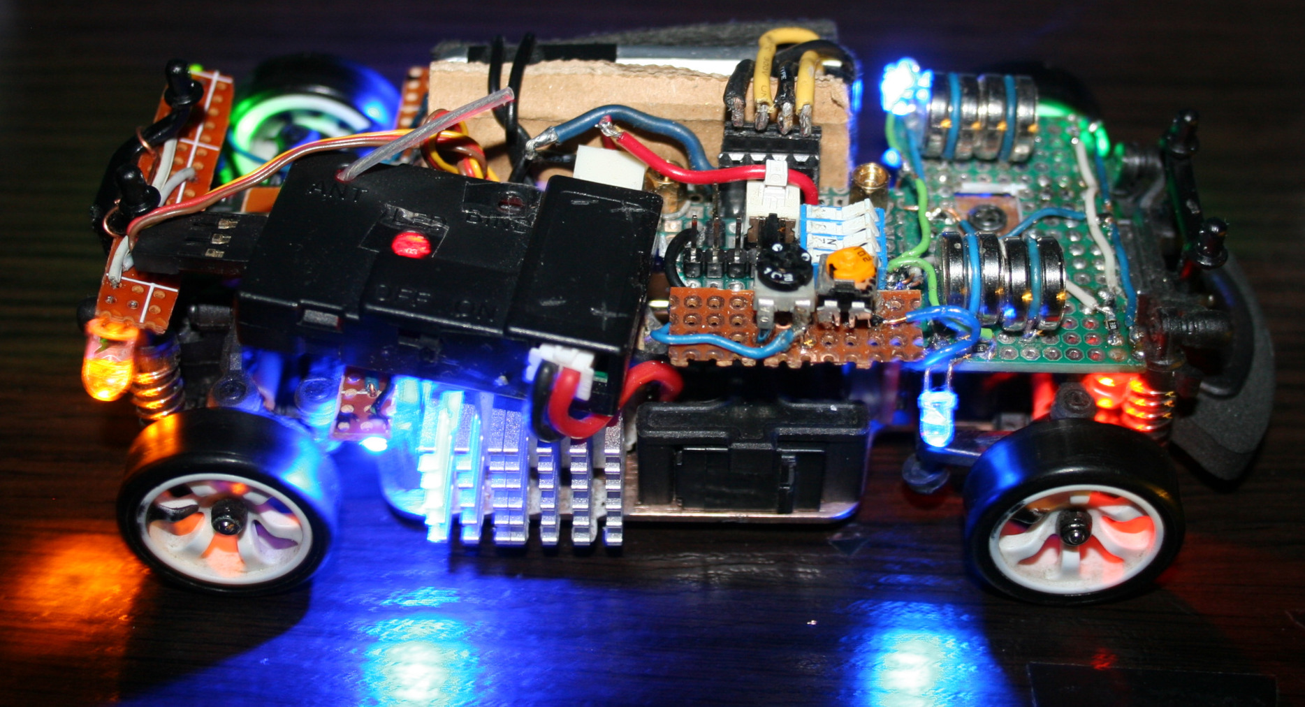
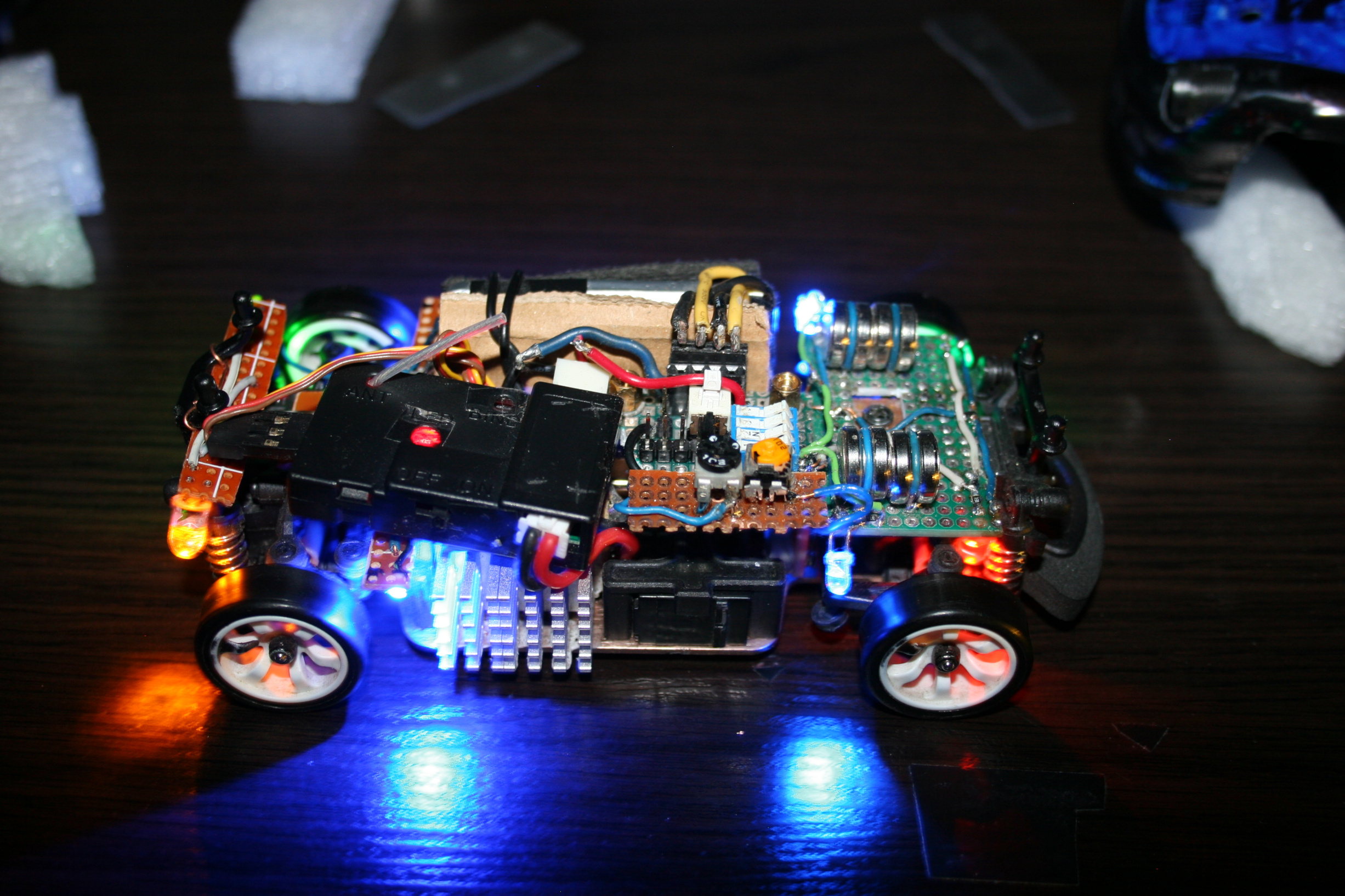
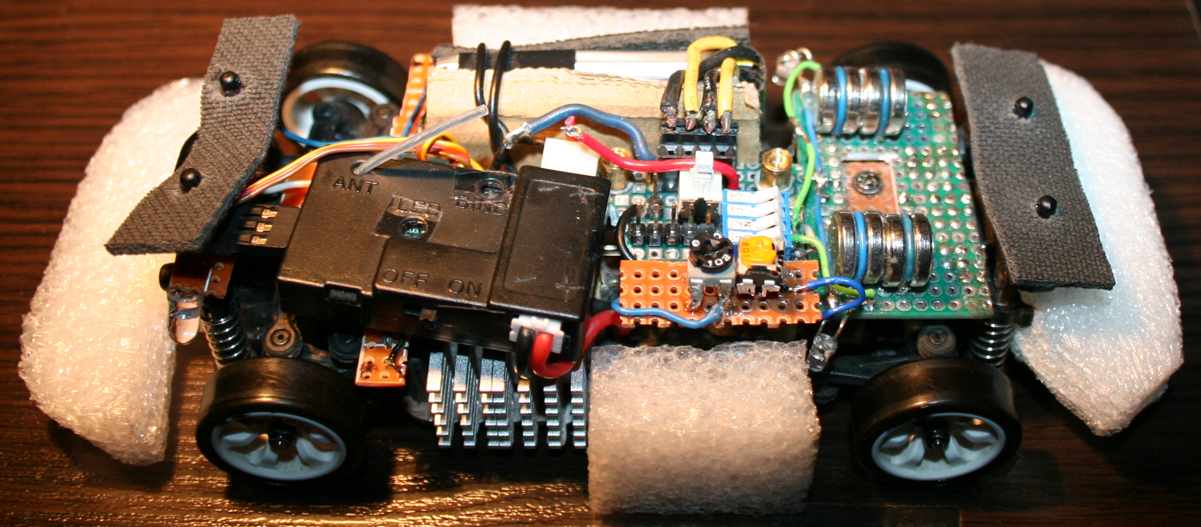
Added more weight on front. I cut out a universal PCB (my favourite kind) and made a place to solder down wires holding extra weights, they fit well. I used 4 in total, 2 on each side. One weights 4.5g, so this is 18g added on front wheels. This made center of gravity to shift (like 6mm or so) towards front and made the car oversteer even more, it drives better. There were some videos on doing that, just gluing 10g weight. Isn’t crucial though, still can drift without this. My front PCB is also used for lights and wires.
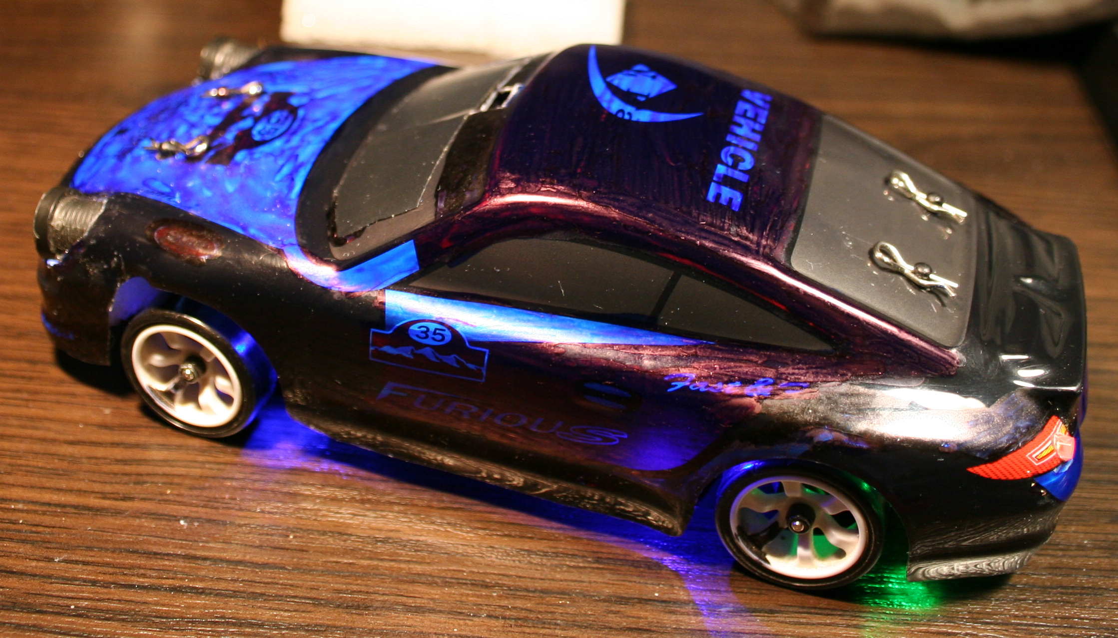
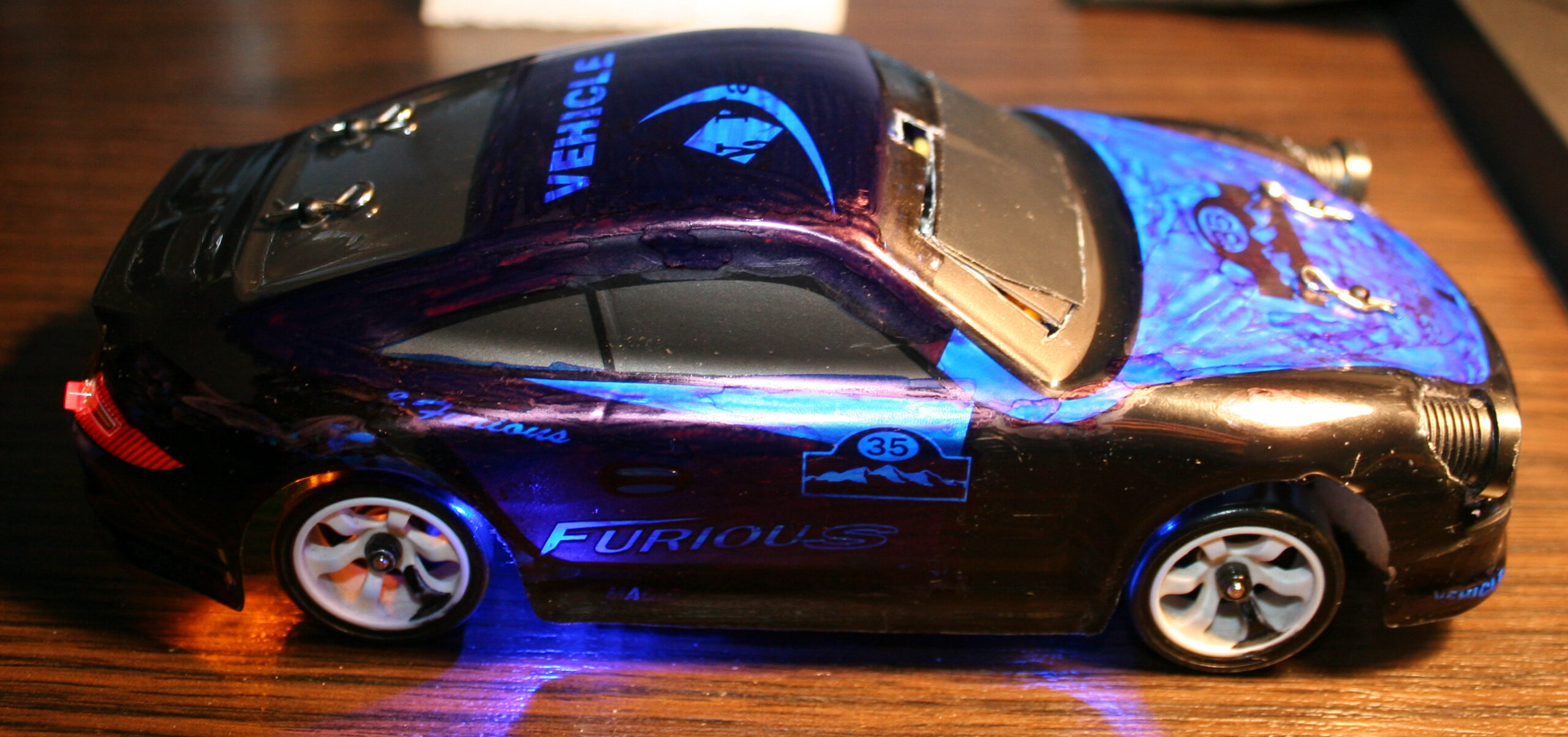
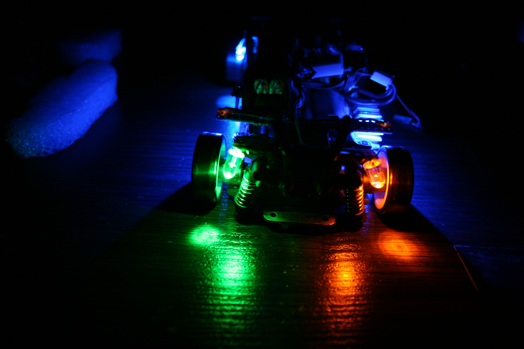
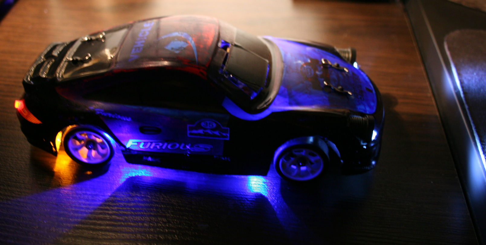
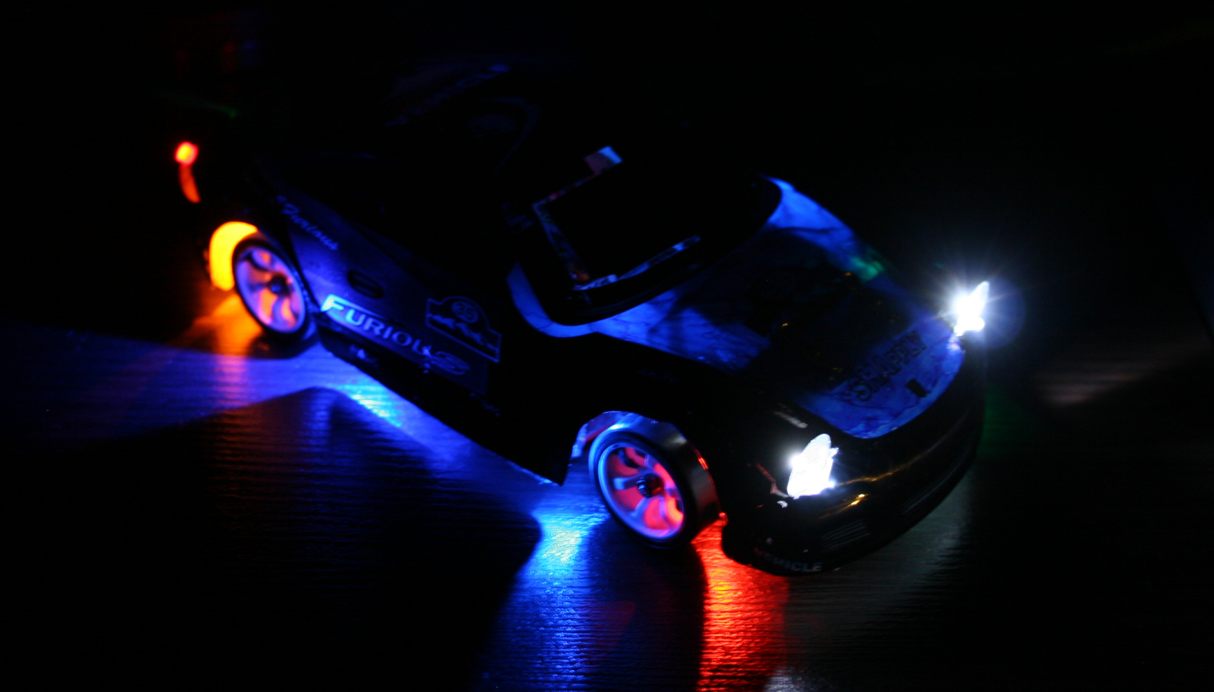
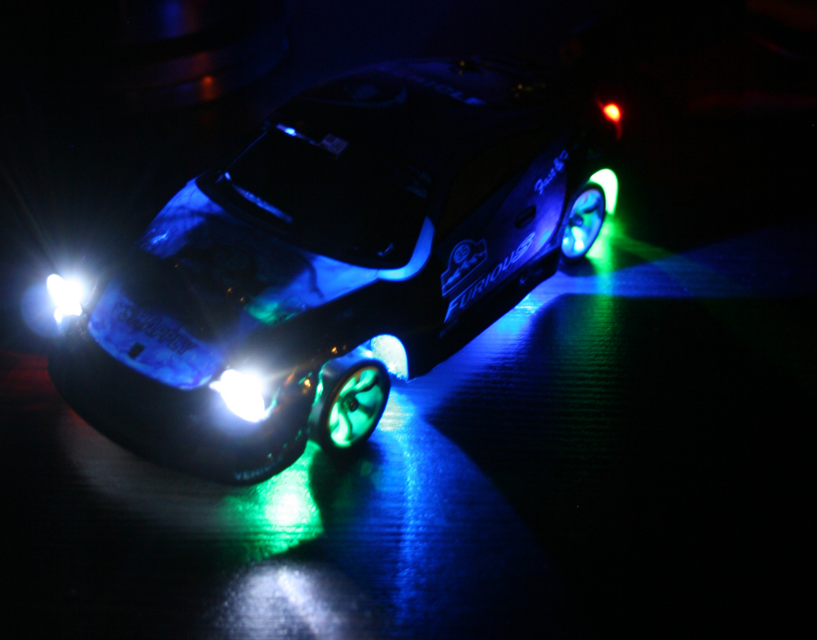
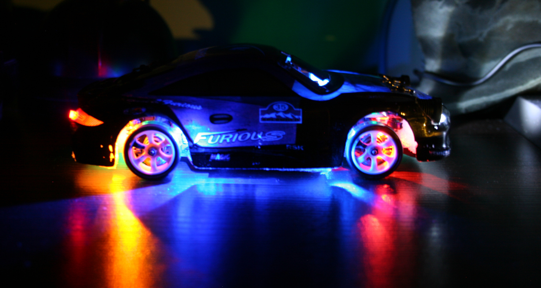
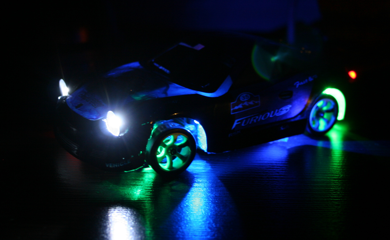
Added front and rear car lights. They are good for better orientation of how the car is rotating and what’s its direction. I mean it is actually easier (for me) to tell this by seeing those lights on floor, especially if car is far. The only way of doing this is making holes in chassis and hot gluing LEDs to it. I’ve spent too much time with lights, first making them in car. This way anytime I hit something harder they would change angle, go loose or break off. I also made a second mistake and made holes bigger to have LEDs with cases. It turned out the cases were too big and so long that made wheels hit them, if chassis is low. I will cut them to minimum and glue again. Good thing about that hot glue is that I can actually melt it with soldering iron again when I change my mind.
Made the RF sender battery use a 18650 LiPo. I don’t get why they didn’t already (was probably cheaper). When full, 4 AAs give 6V, LiPo is 4.2V, but RF sender still works. I thought it would be more difficult, but it was really easy. Just throw out 4AAs compartment and place the 18650 or any other LiPo here. Doesn’t seem to use much power, I didn’t charge it for a month or more. I only don’t know if it maybe decreases range? But with all being digital it may not be affected.
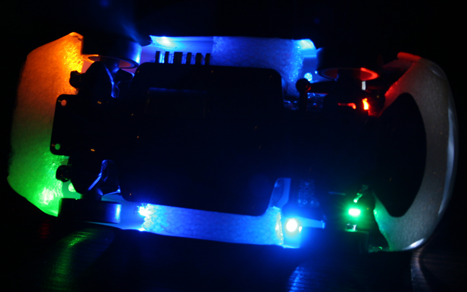
Added bottom lights. I had some old LEDs lying around, now 2 are on rear before wheels and 2 on front before wheels. Their location with chassis holes makes this cool blue X on floor now. I had only two 3mm LEDs so I also used 2 SMD LEDs, which I soldered out from those LiPo chargers (who needs them, red when charging is enough, and were so bright that I couldn’t even?). Then I added two 5mm LEDs (too big, SMD are better) green on left side, yellow-orange on right, located right after and above wheels. This turned out to be useful to know even better how the car is rotated from distance. So later I added same (close) colors to front, behind wheels. I soldered all on small cuts of universal PCBs.
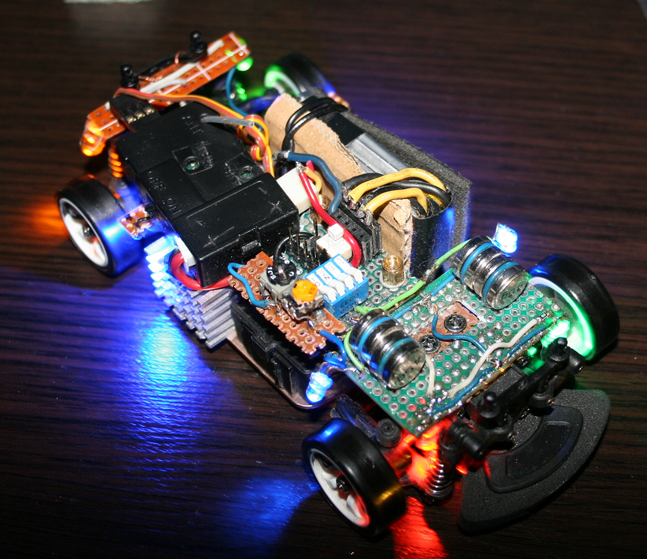
Changed to a bigger car battery. The included 400mAh battery allowing 30 min runtime is laughable. Yeah I can’t imagine drones with 15 or less minutes at all. It was cheap and light, which is why they made it, right. After all, the freaking top speed has to be highest, like it was important at all. It drifts at much lower speed already. My new battery is 1200mAh and allows 1h 30 min drive time (so 3x more). It was made from two LiPo 603450 batteries, each size: 50x34x6mm. Glued with tape, fits nicely in same place, is just much higher and it weighs 45g. Secured it with some cardboard and mouse pad fragments on sides and wire (with thick insulation). I just had to remove their protection, because with it, it would stop for few seconds when pressing throttle too rapidly (very annoying).
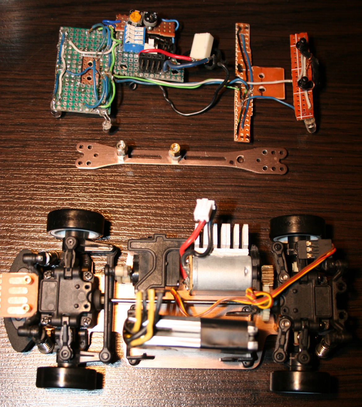
With new battery I’ve also done new electrics in car. namely:
4 pin socket for battery, normally plugged in.
ON-OFF switch. I used a 6 pin Tactile Power Micro Switch (self lock on) 7*7mm to switch + from both LiPo batteries.
4 pin socket for charger, plugged in when charging.
4 micro switches for lights (on-off, one small package). I added 47Ω resistors at end of each. I call this a fuse box, their purpose is prevent battery short circuit if by accident some wires connect.
5 pin socket (3 used now) to connect chassis lights.
2 trimmer potentiometers 1kΩ, for dimming car lights and bottom lights.
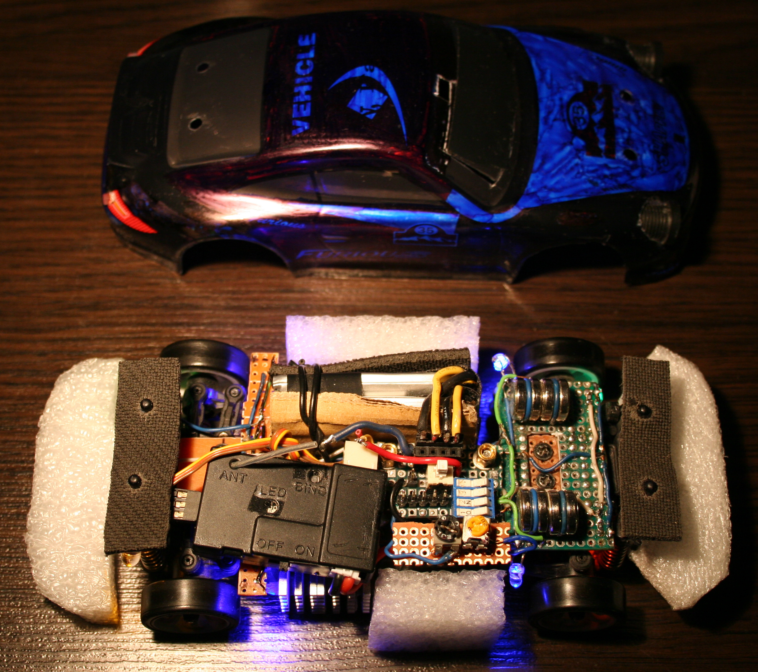
All this required access, so I made a “door” in half of car’s front windshield.
In total, the boards with bottom LEDs and all electrics weight 27g. Seems too much, but whatever?♂️. Each LED has a 330Ω resistor before. LED calc can be used if needed.
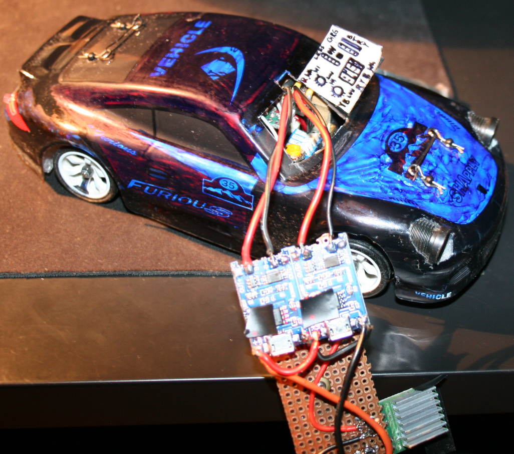
Charger Made using 2 popular modules: TP4056 / TC4056A Lithium Battery Charger and Protection Module. Just added 4 goldpin connector for car socket and that standard 4 pin PC connector for 5V. It does charge the battery in about 1h 30min. I’m not sure if it’s too fast or okay. The 4056 chips are heating a bit too much (at start), so I’m using a small copper radiator on them. Besides of removing blue LEDs from chargers (mentioned earlier) I also reduced the red LEDs brightness, resistors are now 20kΩ (way more). I hate this approach of adding LEDs, even for “turned on” indication and making all LEDs as bright as it can be. I guess if they could they’d made them visible from space or neighboring countries, that would be the best commercial.
Radiator for main motor. Having more time to drive showed that it heats a lot, especially in smaller rooms. So I used thermal glue and glued some small aluminum radiators (1 cut to match motor length) bottom to motor and side to car bottom, which is aluminum, so good for cooling too. I’m guessing an even better way could be using copper tape around motor and gluing that to car bottom? Not sure. Either way some cooling is needed and would be better to have it done already.
Added some rubbers (cuts from mouse pad) below chassis mounting points (I saw something similar in a video). And later some foam around the car, better late than never. This is to soften hard hits, those happen a lot at start when first learning to drive, especially without reduced throttle. Additionally, at home I do jumps sometimes, banked and U turns (up to like 80 degrees, on a bent sheet of metal I had in cellar) and flip overs can happen this way etc.
At some point while reversing I almost broke one differential end (those, like all parts are plastic). I only noticed when one wheel wasn’t driven. But I managed to put it together with a wire soldered around it, so it doesn’t fall apart completely and works, a bit uneven though. Parts are freaking expensive, probably few times more than their worth. I hate this approach. If someone bought all parts separately it would cost like 2 or 3 times more than the car itself. Plus the waiting for shipment takes time.
After some bigger hit, I broke the thing that holds chassis on front. It is filled with holes and plastic, so no wonder. I made something stronger (and heavier like all I did) from a metal part, M2 and M3 screws. Is more difficult to use but should last longer, if I don’t break the plastic part that it’s mounted to.
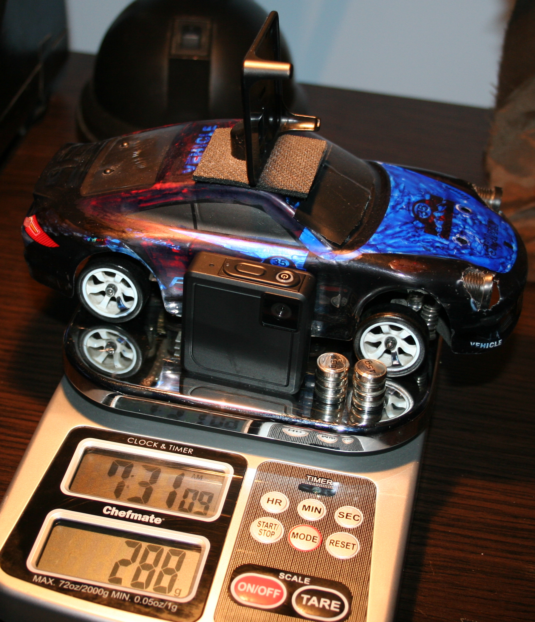
Added a mount for camera on roof. Camera is Ion Snapcam LE, it weights 28g, with its own battery. It even lasted longer than car drive. I didn’t yet make it lighter by using car’s battery. Not sure if I will. Unfortunately, videos are horribly shaking when driving, because of uneven wheels.
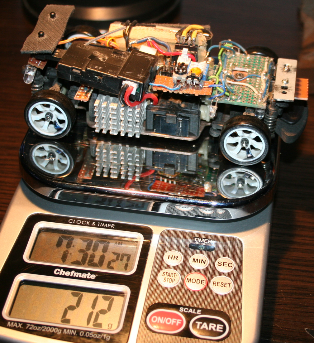
In total the car with camera weights now 288g. So it is a lot more (was 160g at start) and the front suspension won’t allow more. Without camera and extra weights it is about 240g. I think it still drives well despite the extra weight. But surely when lighter it was quicker and more responsive (less mass and inertia).
Now I’m waiting for new wheels, with aluminum rims. The default wheels on this cars are cheap, all-plastic and uneven. Even like 1mm difference in height when rotating. This makes the car shake a bit. Surprisingly it doesn’t affect driving somehow, and it wasn’t easy to spot. Only slow time videos showed it and those from car camera, which are rather unusable.
Maybe for future (not sure if I’ll try/do any of these): I was thinking of making the controller use IR distance detection for throttle (instead of potentiometer which I already once cleaned since dust made it go chaotic). Using a MCU (Teensy 3.2 which I have lying around doing nothing) with LCD, buttons and rotary encoder for a GUI that allows adjusting all ranges and offsets without potentiometers. I also had an idea about having a light MCU in car to use RF (e.g. NRF24L01 2.4GHz modules) to send some measurements to controller MCU, like: battery voltage (for remaining drive time), motor temperature, car acceleration, rotation and direction (from those popular new accelerometer chips), and making all car lights toggleable and dimmable (with PWM) from controller. Lastly very doubtful, but maybe if I used PC mouse optics and chip I could get real velocity and position on some surface.
⌛Conclusions / Review
I personally can’t imagine having fun with an outdoor, fast / touring car, with rubber tires. Neither with a smaller car that doesn’t have 4WD and drift. And those big RC cars that can slide on gravel (and jump up few meters) are quite big, very expensive (I seriously would buy a new PC instead) and require a big area or a track. And outdoor and indoor tracks aren’t close, are likely paid per hour and have other people. Plus parts for more expensive cars are of course more expensive.
To summarize, I would recommend the WLtoys K969 car, especially as first RC car for indoor use, with more fun because of drifting. But with a few remarks.
I don’t really recommend driving this car without modification 2 (throttle range adjust). I did it at start and it was chaotic. Some say modification 1 (more steering) is also crucial.
Another thing that many say, is that the 2 smallest gears wear out rather fast. Those that drive each differential, both from plastic again. Why on earth aren’t all gears from metal.
Well as I mentioned few times already, nearly all parts are from plastic, which can be a problem. Surely is for small gears. Later if you drive on uneven surfaces or jump, etc. then mountings for suspension will wear out or break (since closest to floor and from plastic). Still (and maybe that’s why) there are many metal upgrade parts and kits, but I don’t recommend any, at all. I have seen too many negative comments from people who say that those don’t even fit together, are bigger, leave less clearance etc. So they just look cool, and that’s it.
The rest of my modifications were optional and just an easy hobby, that lets me spend some fun time, but not with my PC as usual.
This will be a somewhat unusual project post. I normally don’t show off stuff that didn’t need much creative work, but in this case it has a very long history (since 1997). It has gone through many modifications and it is still used every day, now in our kitchen for playing music.
📜History
It all started as a Panasonic RX-FT530 Dual Cassette Player (pictures). My mom bought it for me in 1997 (its production date inside has 1995), before I started technical high school. It was also around the date when I started learning electronics in practice and later in theory (ugh, from 20 years ago) at school.
Since then it has gone many changes and had lots of features, many of them aren’t present now:
🔵Blue LED for radio stereo indicator. Obviously for me, the first thing to do.
📼A switch for super fast cassette rewinding (Do feel free to spool through). Tape looked after a bit uneven inside, but very useful.
🟢Green LED lights under both cassette decks (in middle) to see where the tape is at (how much on left and right barrel). Also extremely useful.
📂I removed the closing decks, and was just having cassettes clearly visible while using.
🔸A small LED for the marker on frequency ruler for analog radio. I think it broke at some point leaving me without a ruler. I guess due to putting it apart and together again, fast and too many times, while not caring much where I place its parts.
💦Not sure when (around 1999), I splashed it with (white, silver and gold) oil paint, from PCB markers I had back then (obviously too many).
🕰️A digital clock, at some point on right side. Wasn’t very accurate so it didn’t last long there. Left a switch and 4 places after its buttons in back though.
🎛️More input sockets, output audio socket to other amplifier, switch for it etc. I remember at some point of experimenting with other amplifier I accidentally put like -30V into HiFi, killing its power AMP chip. Which I then replaced, was a good challenge. While still being a teenager I obviously needed this HiFi.
🕳️Since these became not needed later, all holes got covered with black tape (at least 10 already, in total).
⚡At some point I added a 5V regulator 7805 and USB sockets so I could power other devices from HiFi, e.g. a LCD clock / weather station, further on shelf. (Instead of ridiculous AA batteries. One can use a 3V regulator or a resistor (e.g. 200Ω) with 3V zener diode). At that point I didn’t yet know how to make a weather station myself.
🪦It has spent a few years, abandoned in cellar. Gathering dust and wishing for a better future.
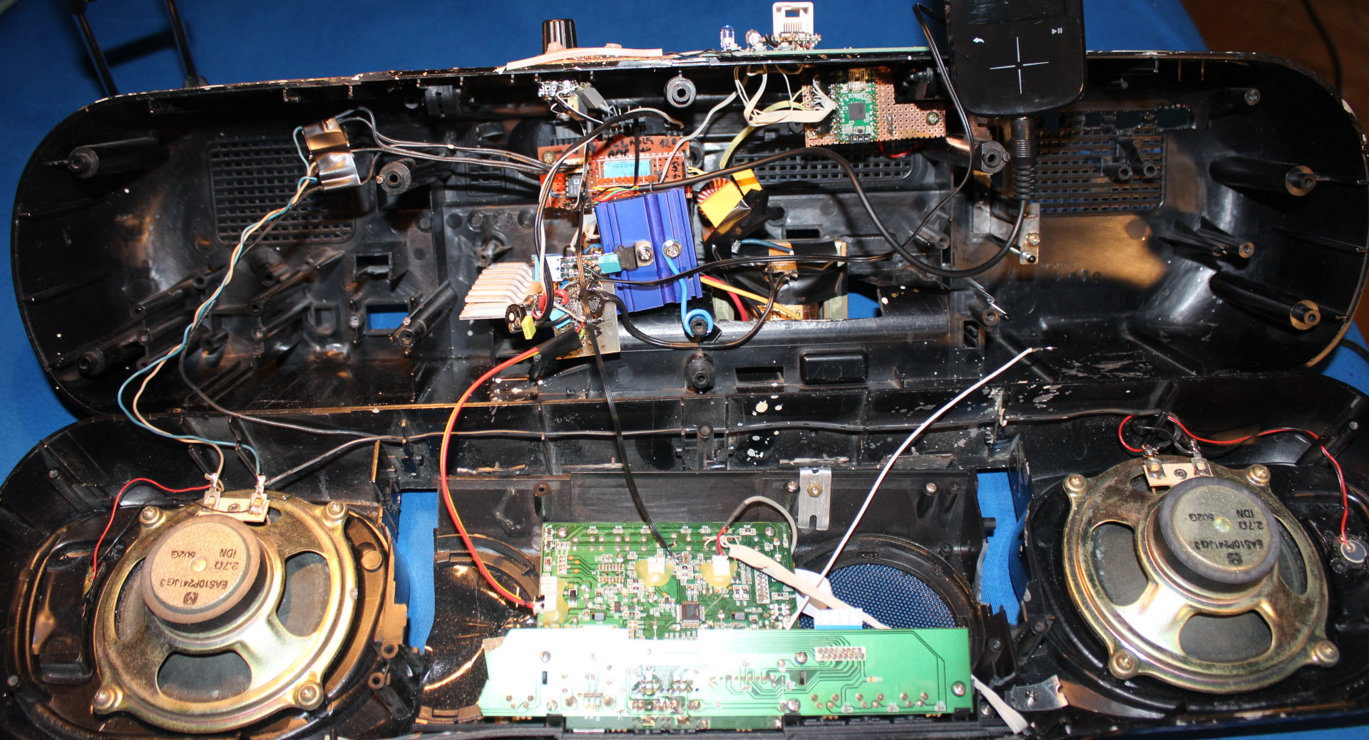
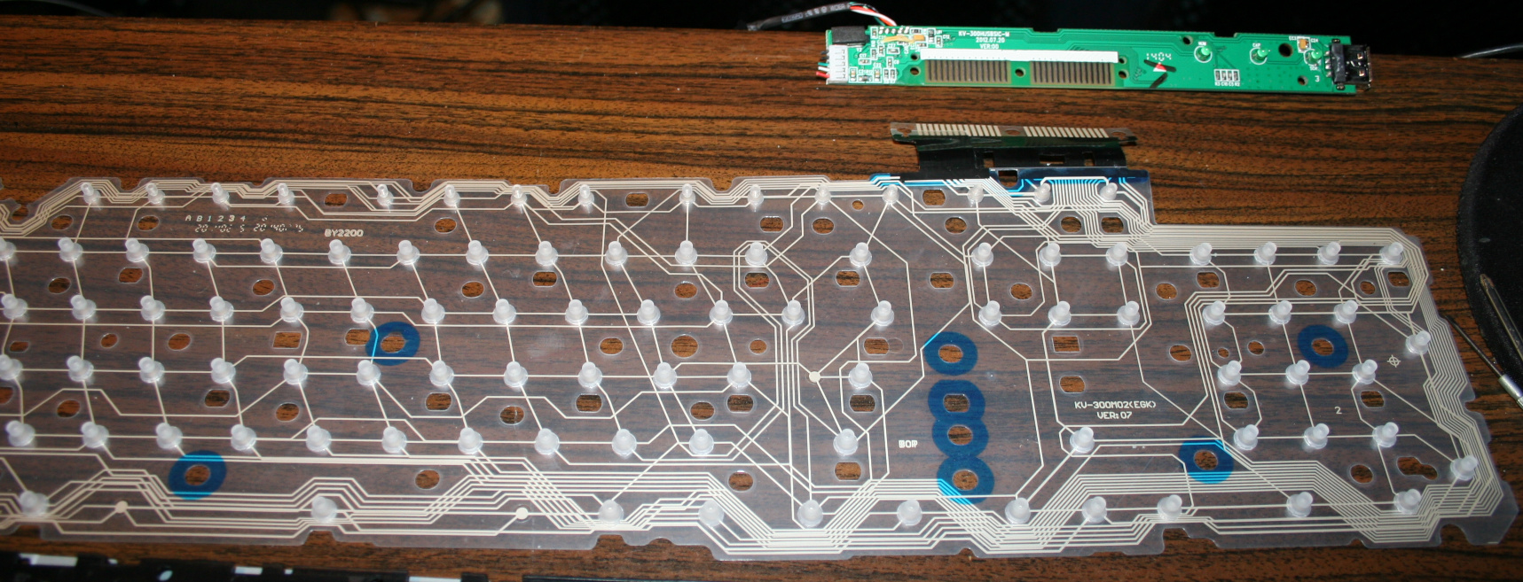
📼Many years later, I ended my history with cassettes (recorded them on PC into FLAC and OGG, and threw out after). In 2020 the cassette decks (with all that mechanical nonsense and engine) flew out to electronic garbage bin too. It was just the amp and radio then.
📻I wanted to have a digital radio, that stayed at given frequency. And BTW a MP3 / USB player, why not. So I ended buying a cheap, local, 2nd HiFi (anyway with Chinese components) which just featured both. It had crappy sound due to small speakers (no bass at all), we used if for short, but naturally I wanted to merge its insides into my old speakers from Panasonic.
🔍Details
The final “HiFi” currently features a digital radio, USB or SD card player (from that 2nd cheap “HiFi” product) and analog input. Its radio forgets frequency after power off though, so power is always on. It was too in Panasonic, IDK why, using about 0.5 to 1W constantly, power amp is likely always on.
I scrapped that stupid Class D amp (MIX3018) from 2nd HiFi, I prefer that AB, although it has too much power. Then located its audio outputs and connected to old LA4108 power amp (low quality, too much power), but with better quality anyway. Later I also added a double potentiometer (which I even had available) for volume on front, since the original was making noise when turning.
I will eventually just use op-amps to speakers someday, and will throw out the big old PCB too, from which just 20% is now used. Then it will be just speakers and case from the oldest HiFi.
There are now 3 extra buttons on top (power on/off (hold) / input, next and previous) to control 2nd HiFi. Light press switches, 0.5N force, my favorite. I put rubber cover on top, to protect form any liquids💧, this is kitchen after all🫖💦.
For a while I had a cheap tiny Bluetooth receiver in analog input, powered from USB, but I dropped it, too much noise and once a while it did reconnect etc. Audio cable is more reliable, even cheaper.
I still use its regulated 5V outside but in different connector (PC like), to power an outside thermometer (was from a PC case) and a digital LCD clock.
Lastly I added a small white LED lamp, that’s always on, and helps moving around the kitchen at night, before reaching main light switch.
⌛Conclusions
So: why didn’t I just buy a new HiFi that already has all those features, instead of continuing with this old junk? Several reasons:
Firstly, there is no such thing as a product that has all features / properties that I need, with proper control and interface (knobs, convenient buttons, menu, etc). This can only be achieved by continuing to develop it myself according to my current needs. I now see all electronics products just as ingredients for further modification. Ideally I would create one from start, but that’d be too much time and effort spent, just for our kitchen.
Secondly, I am an anti-consumer, I usually hate buying. It needs a lot of time for research, to find a product that is closest to: not a hoax/hype, reliable, functional, fair-priced, still cheap, durable (will work for long), allows repairs, looks okay, black, etc. (all at once; add needed, strike out not needed😄). On top of that I don’t like spending money (I like saving it) to support companies, which constantly produce (soon-to-be) garbage on purpose.
Lastly, it is a fun and easy hobby that grants better, more customized products for daily use.
In 2023 project I upgraded it further, so the story continues there. I wrote more about buying (vs DIY etc.) in my blog post buying.
📷Gallery
It has pictures from 2020 and up, showing old look and the newest merge of 2 HiFis. Needless to say, their cases weren’t compatible at all, so there is a lot of black tape around.
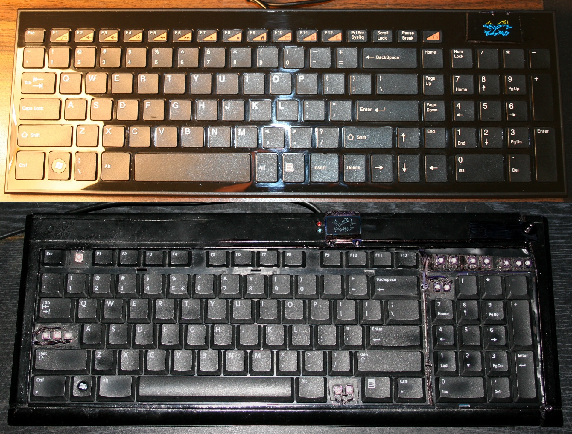
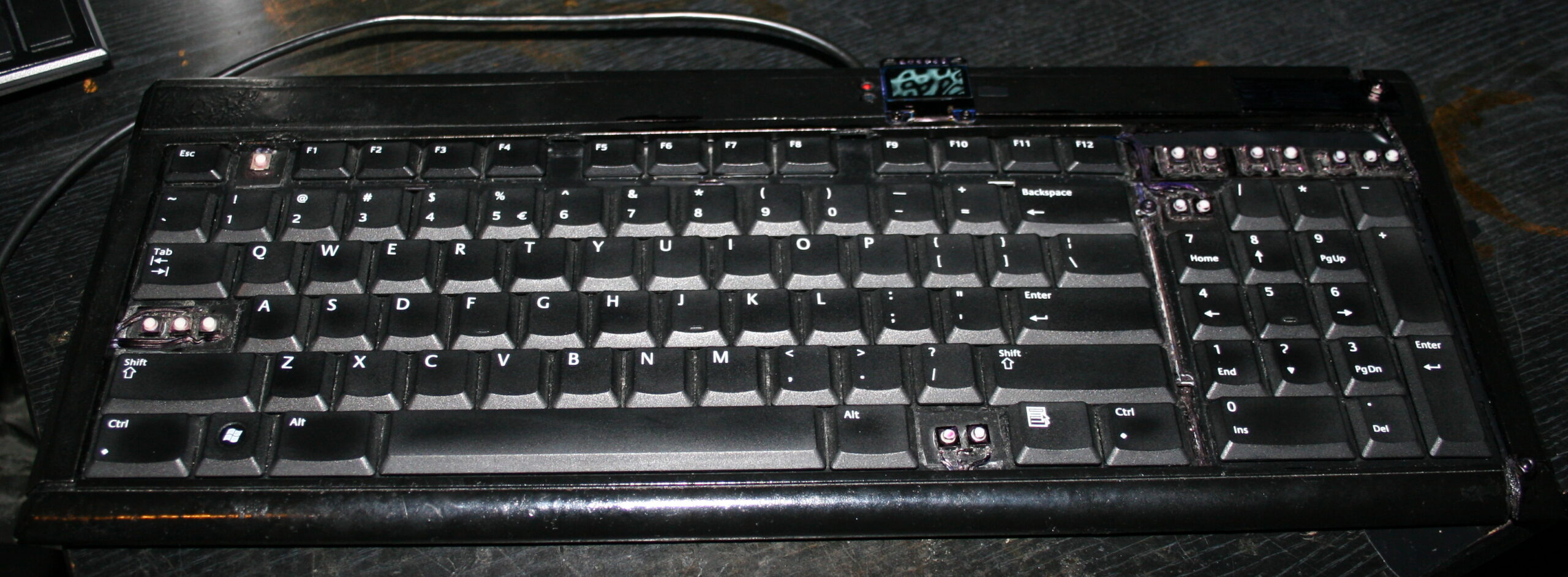
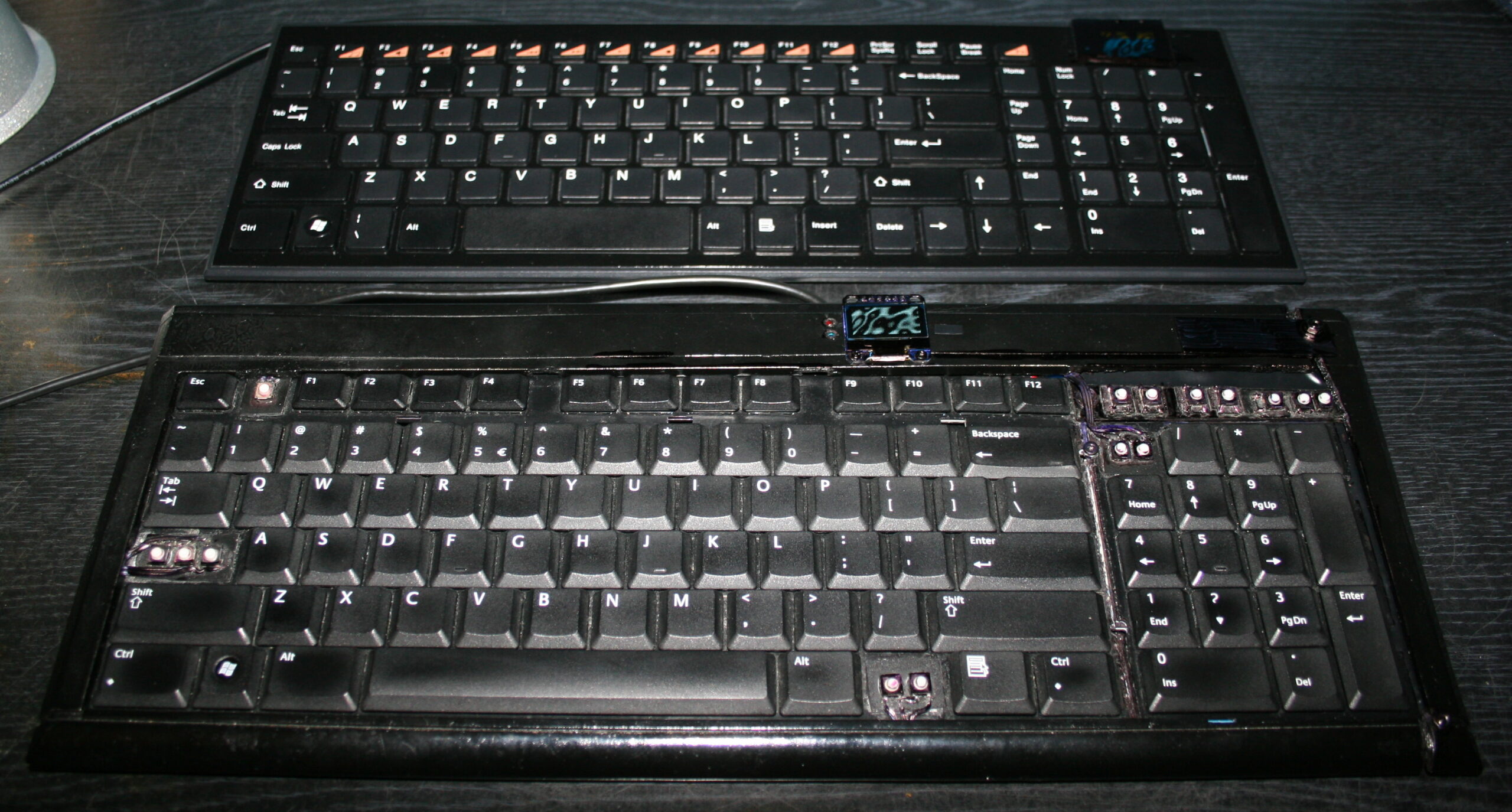
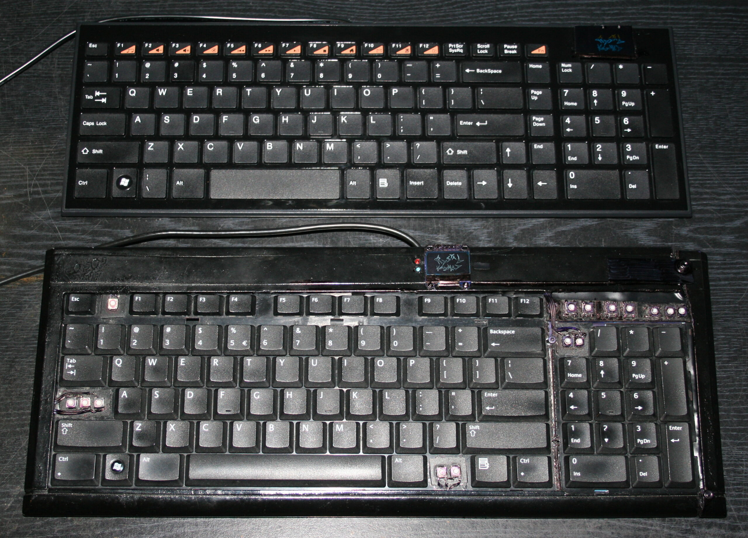
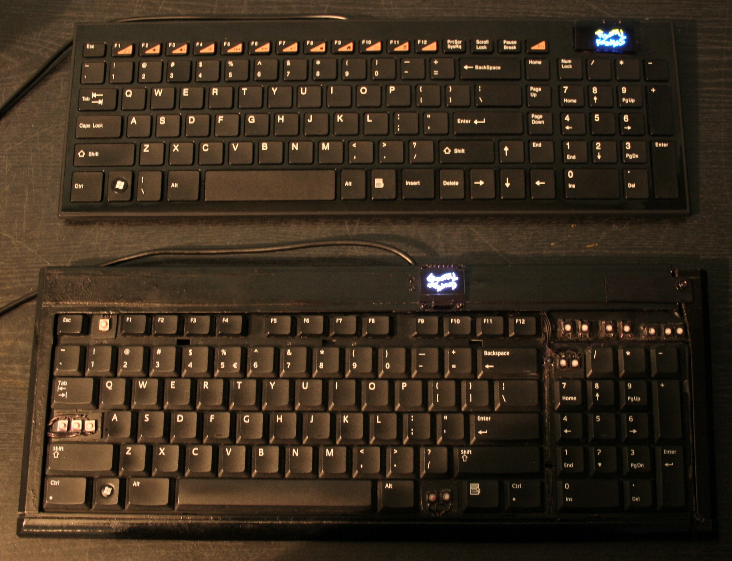
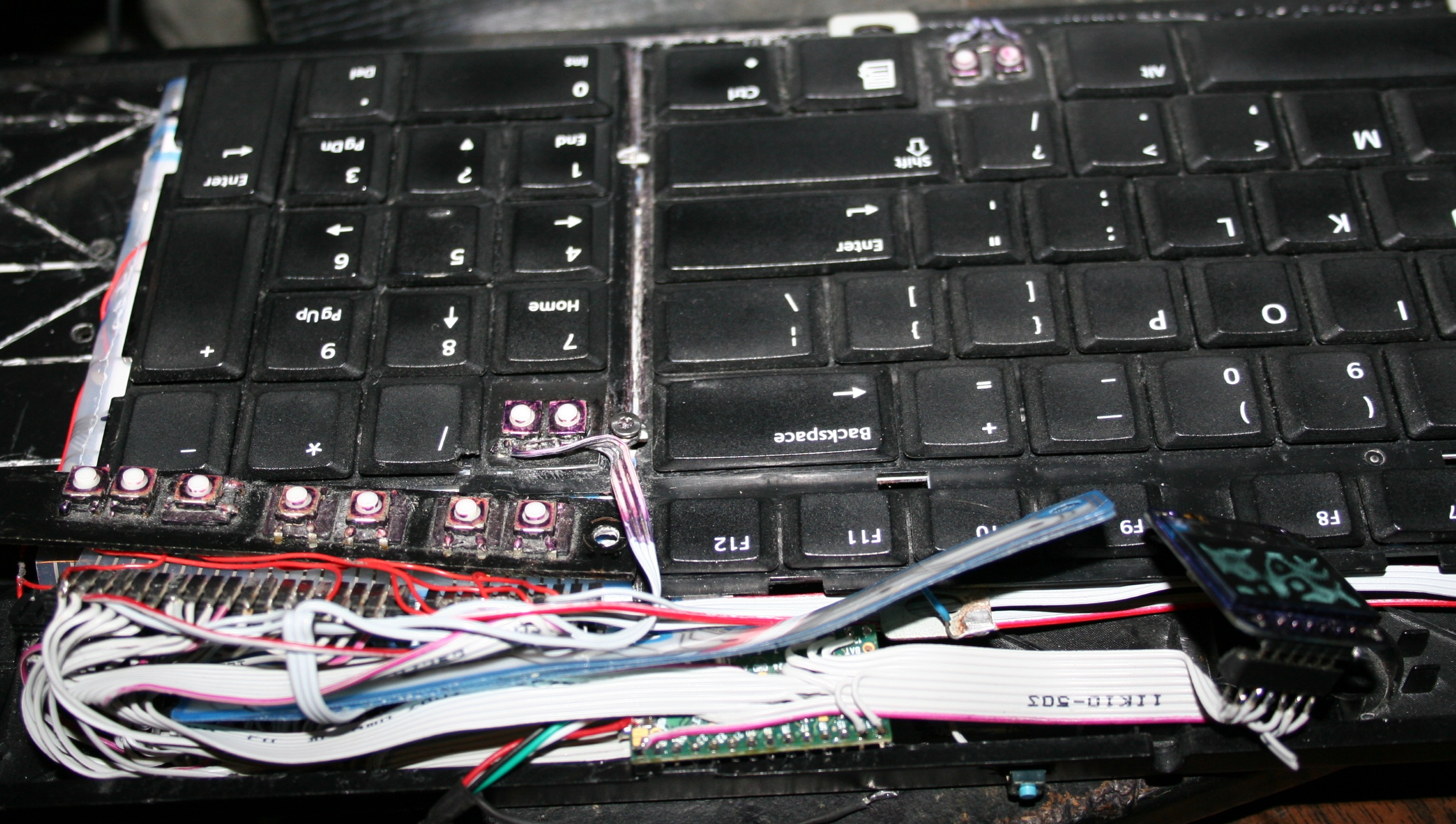
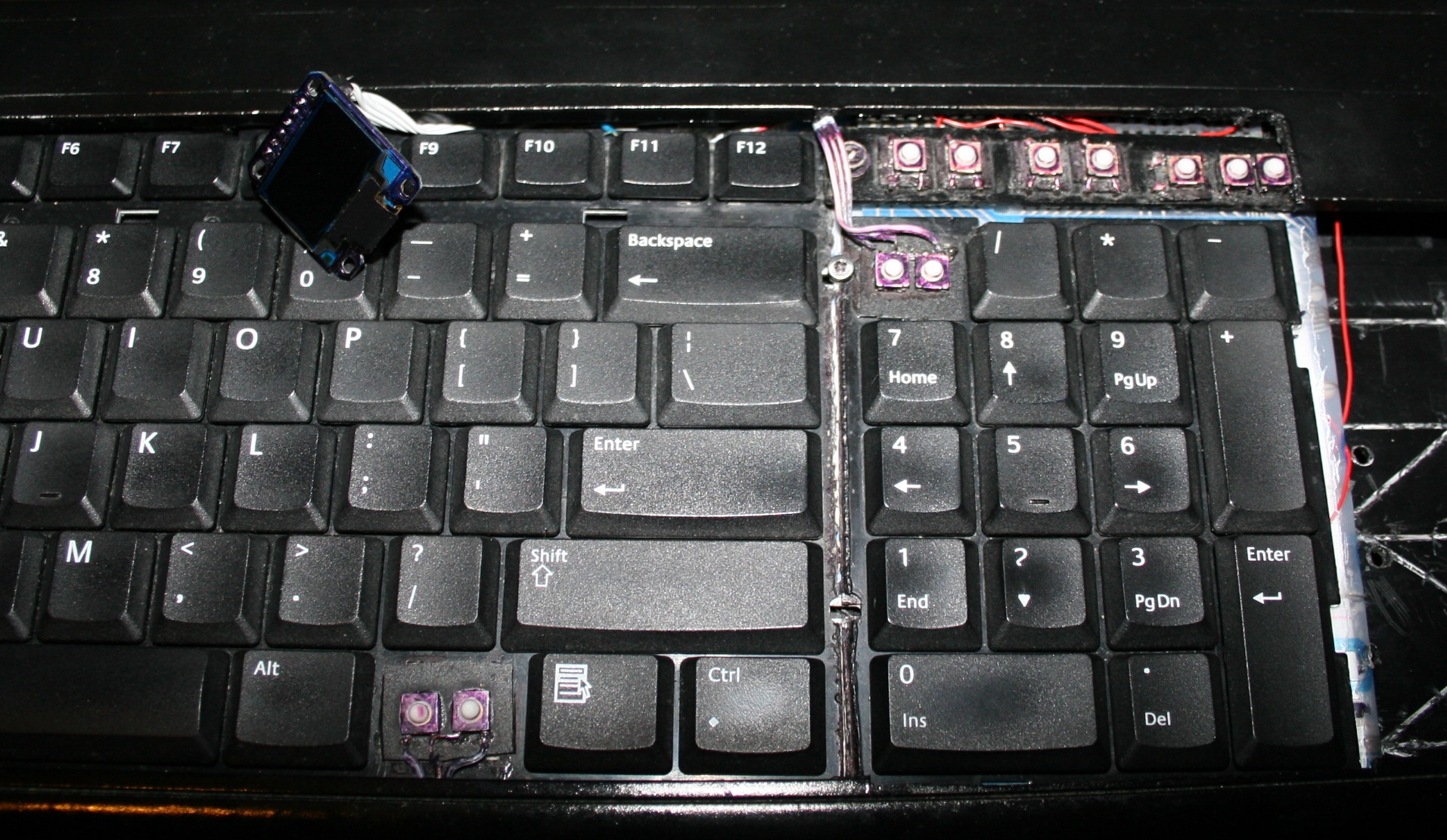
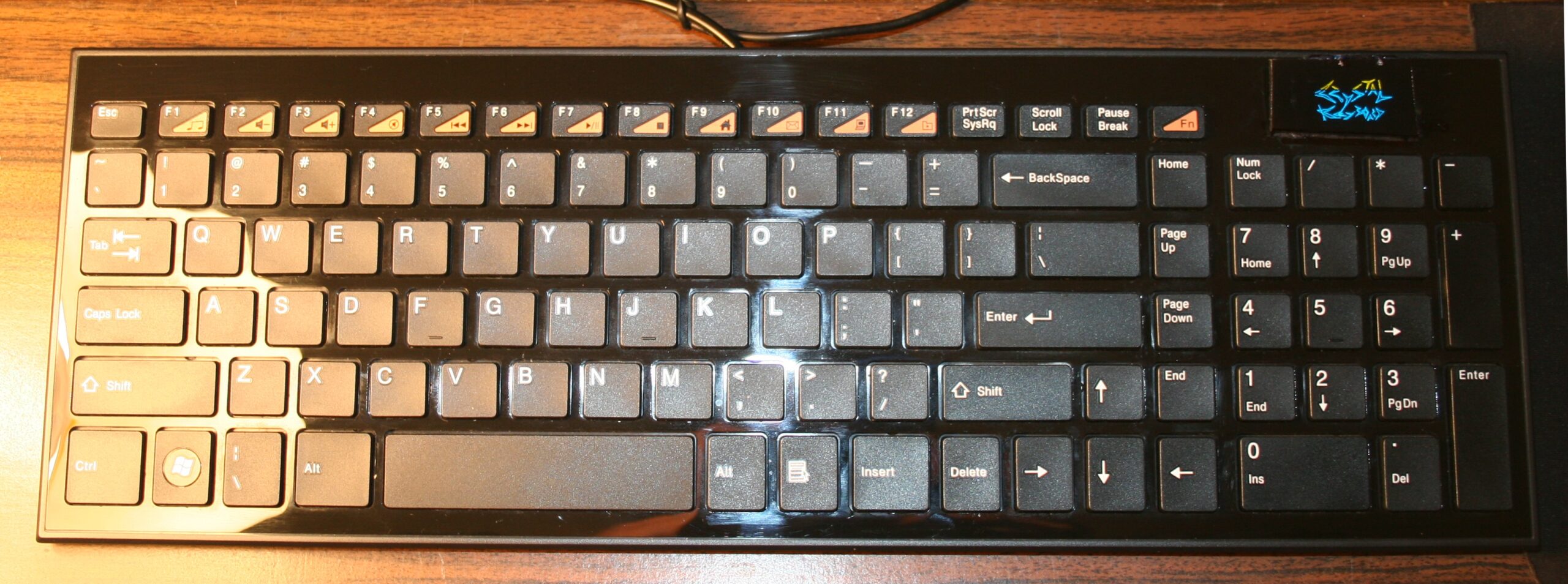
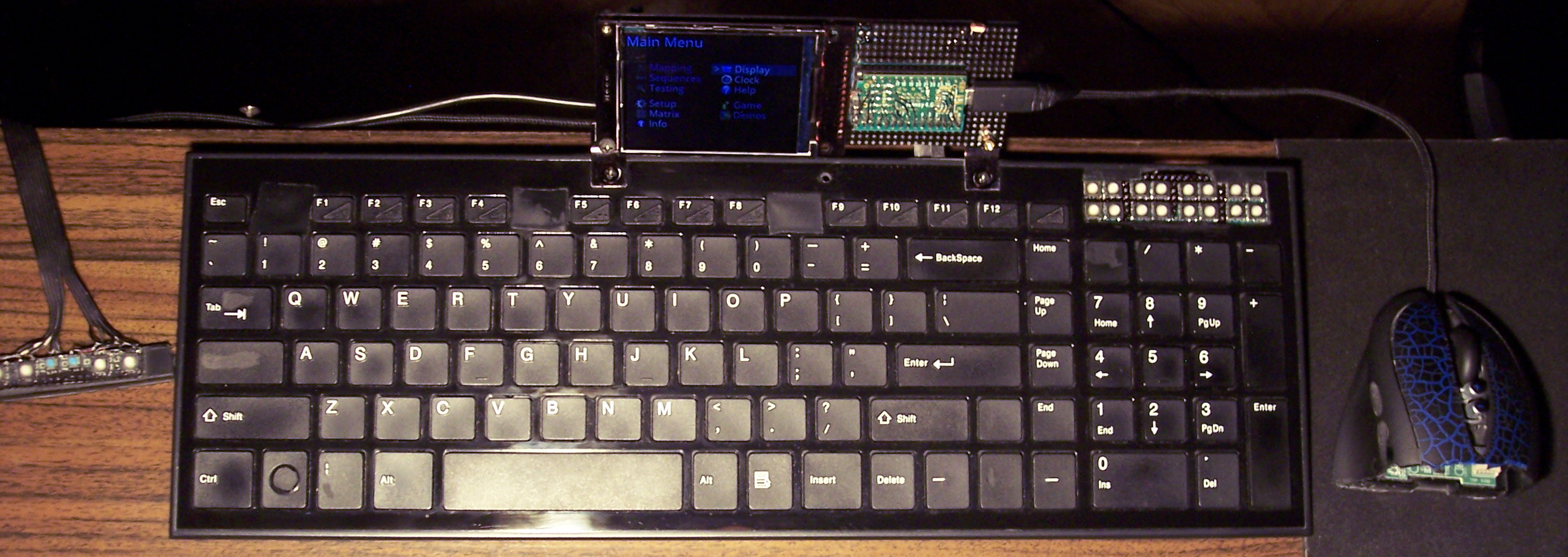
The newer two of my heavily modified keyboards. This time having Teensy 3.1 (or 3.2) as microcontroller with a tiny 1″ monochrome OLED display. Firmware was based on Kiibohd, it was a fork with my extensions. I added display support (with a library), menu for editing e.g. macros/sequences, few demos and a game. I did improve them further in my newer firmware, with bigger display and later made my own in here.
🛠️Modifications
Light press
Rubber domes reduction for minimized pressing (actuation) force and distance. Simply more pleasant and comfortable. Also healthier, since the risk of keyboard injuries decreases. I do it always for all my keyboards. Process with info shown here and in gallery below at end.
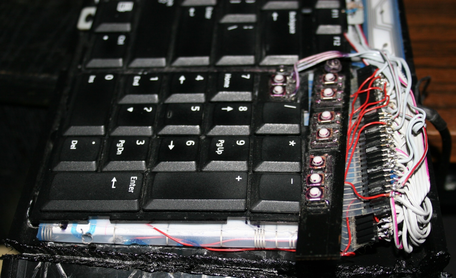
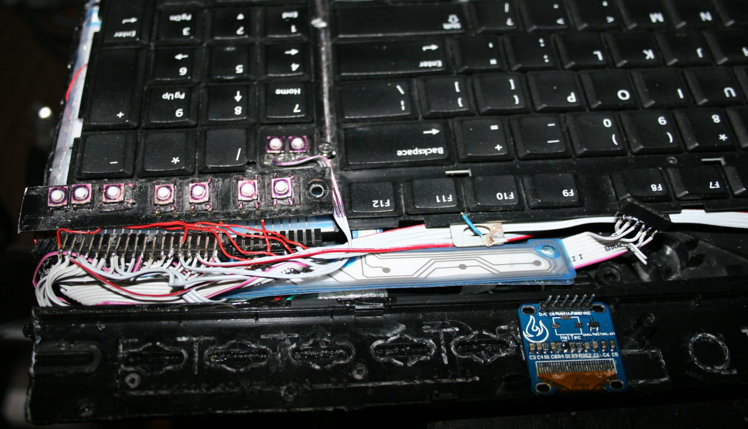
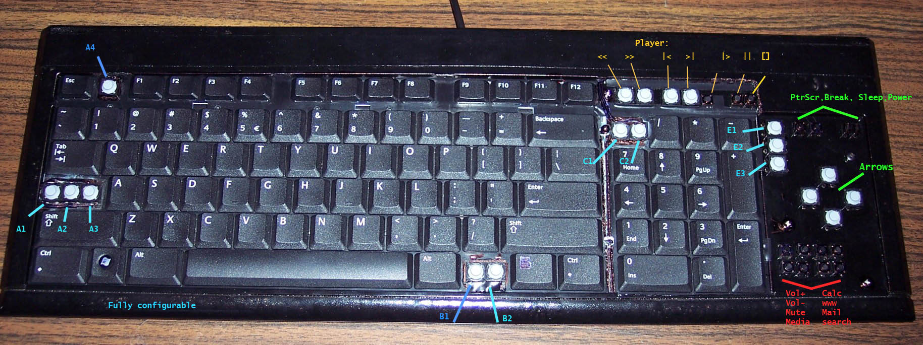
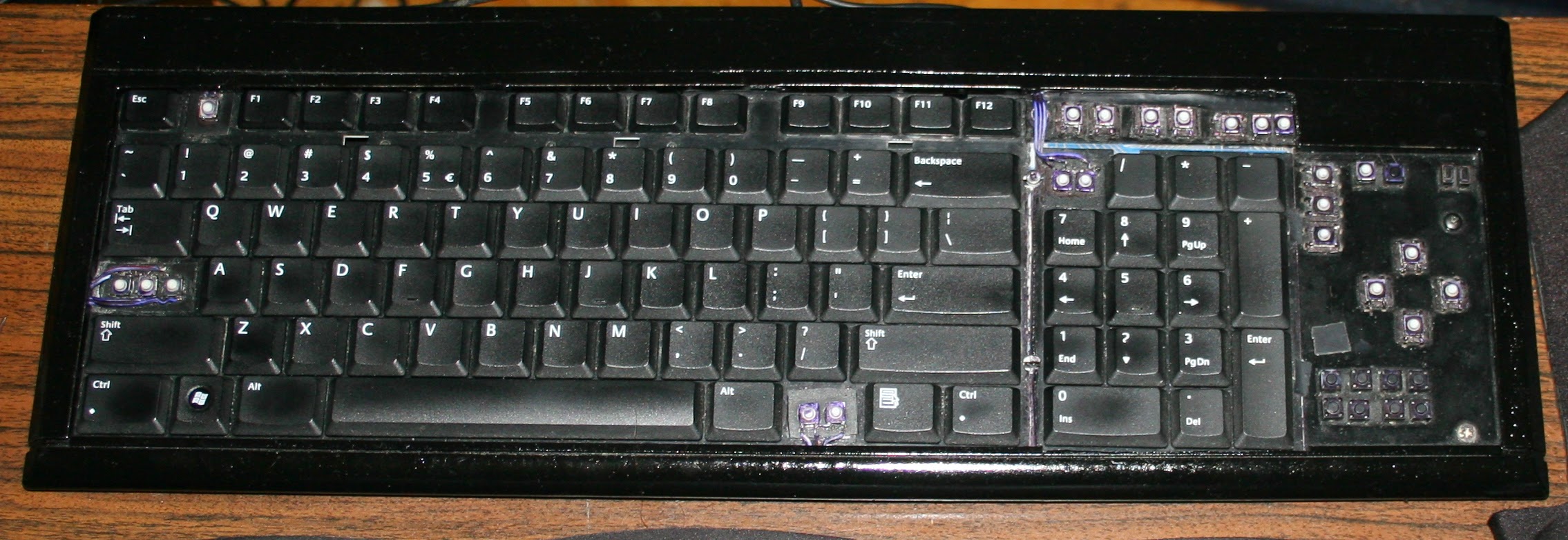
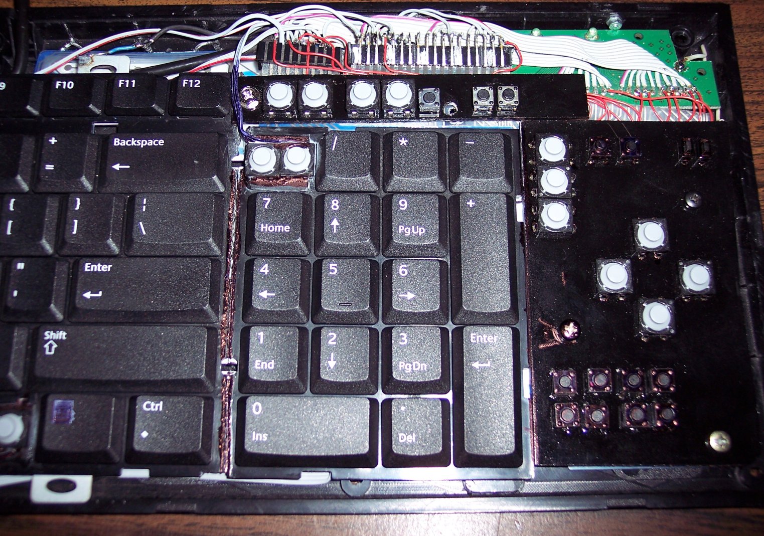
⌨️Additional keys
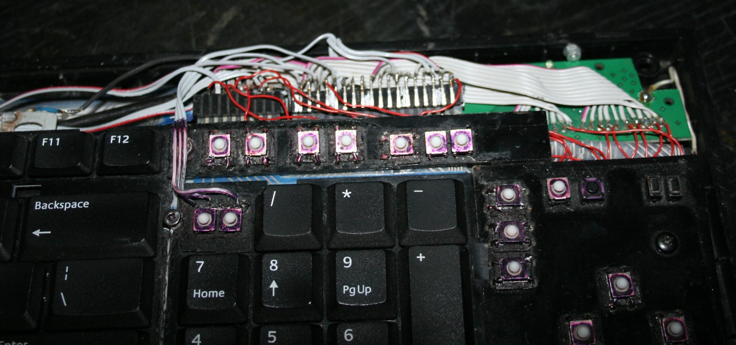
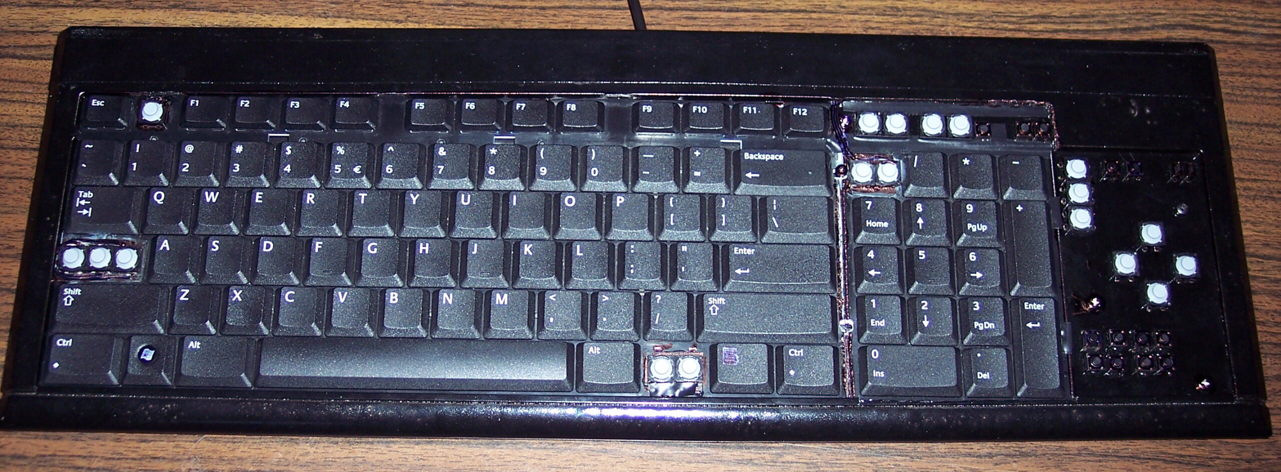
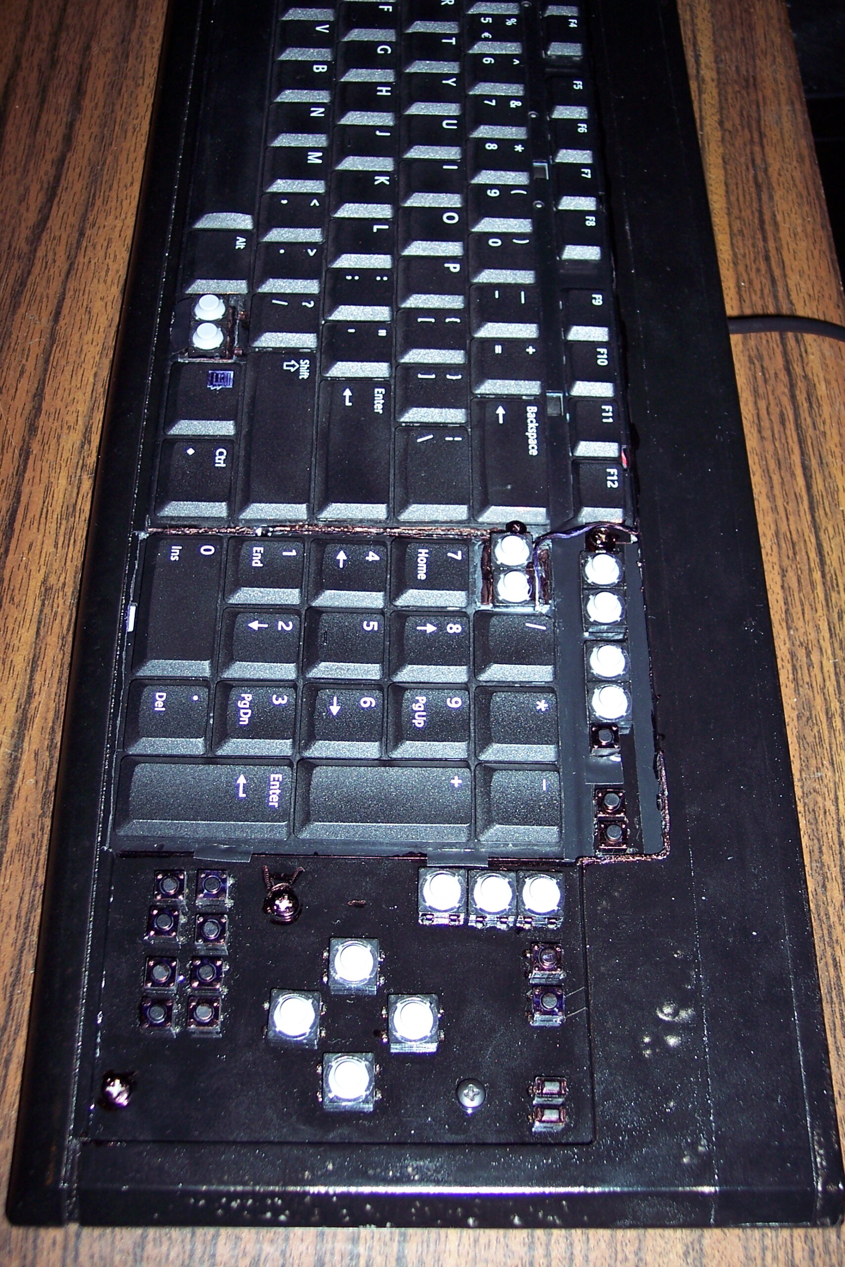
For CK4 there are also few small extra keys. Which were present already in my earliest keyboards CK1 and CK2. Those are glued on top and are made from lightest 0,5N switches available. The row above numpad is used for my audio player control. Rest is custom. This part is optional and I didn’t do it for CK3. The disadvantage is the difference in pressing those switches and much lighter normal keyboard keys. They are smaller so you can fit more, but are less convenient to press. Lastly, regular keys can be used to switch layers instead.
⚙️Microcontroller (MCU)
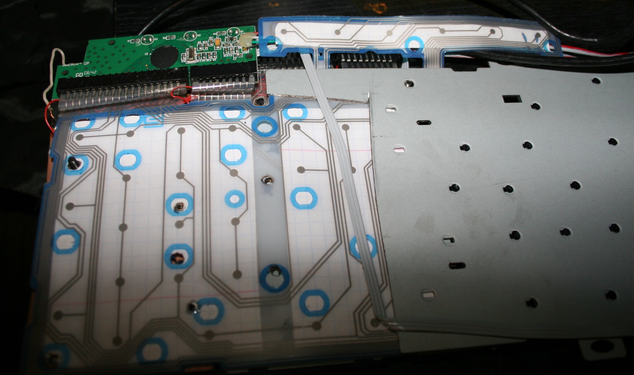
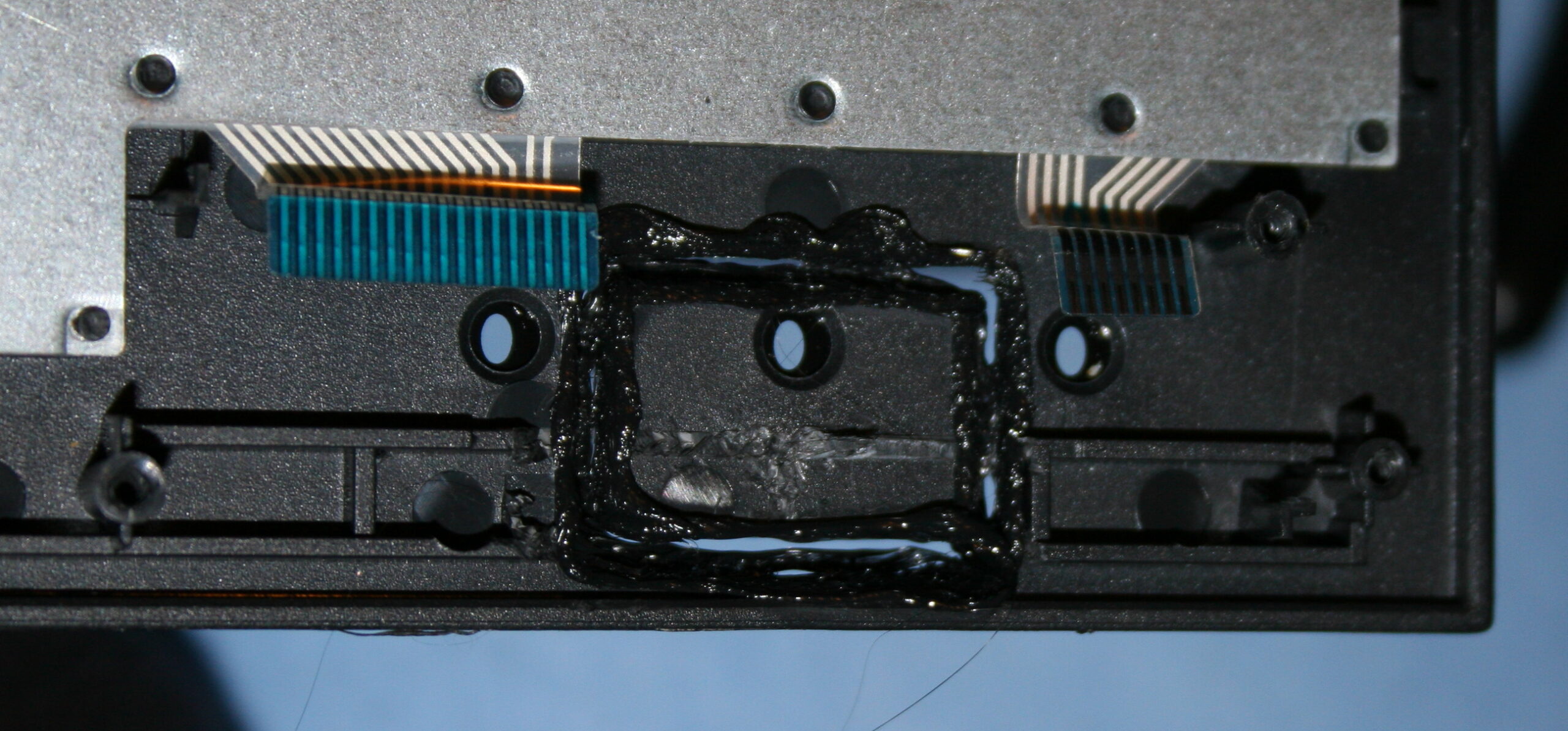
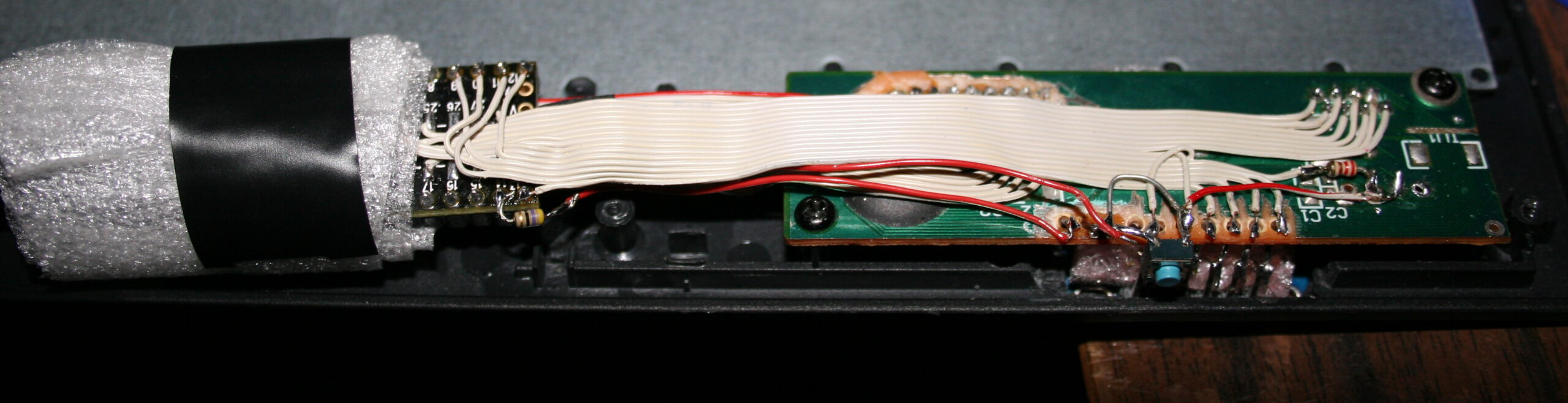
The second step was replacing the keyboard controller board, with my own. The hardware is composed of Teensy 3.1 (or 3.2) with a tiny 1 inch OLED display (SSD1306, monochrome, 128×64) and a bunch of wires to connect to the original keyboard’s matrix.
The reason for this was to take advantage of already made open source Kiibohd controller allowing any imaginable keys assigned and layers. Also possible are macros, key combinations and even mouse buttons and movement simulation. But changing any of this required rebuilding controller software and uploading to controller, through already present USB. Which is a major flaw for me.
📊Features
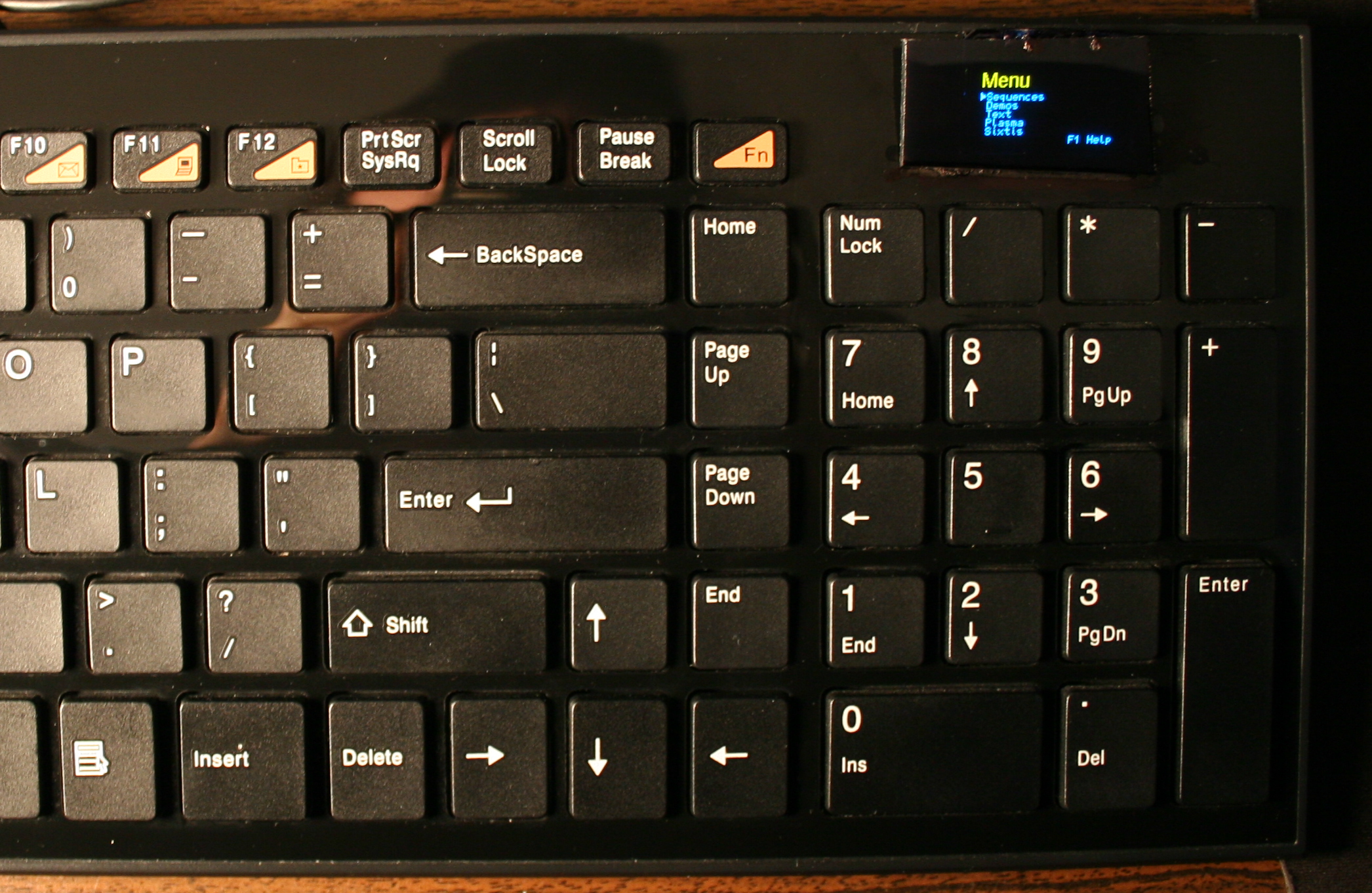
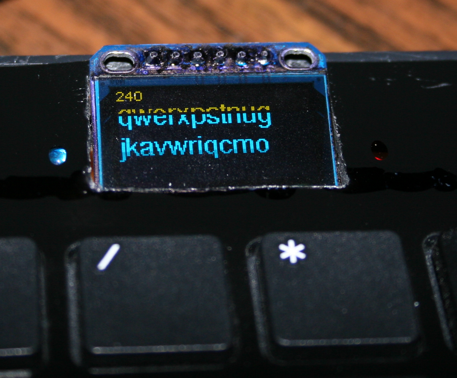
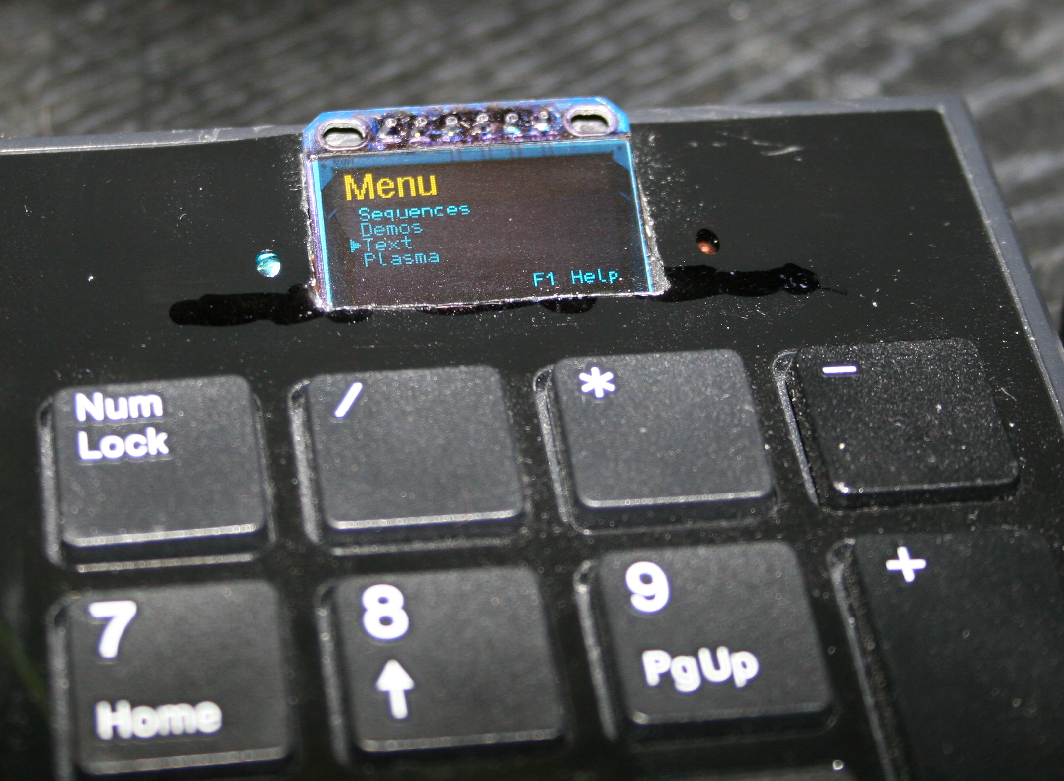
After getting it to work, I implemented my own menu where you can edit sequences, stored in memory (remembered after power off). The sequences are very useful for not typing passwords or simply binding some useful macro combinations or commands dynamically. Which needed a display and menu for entering.
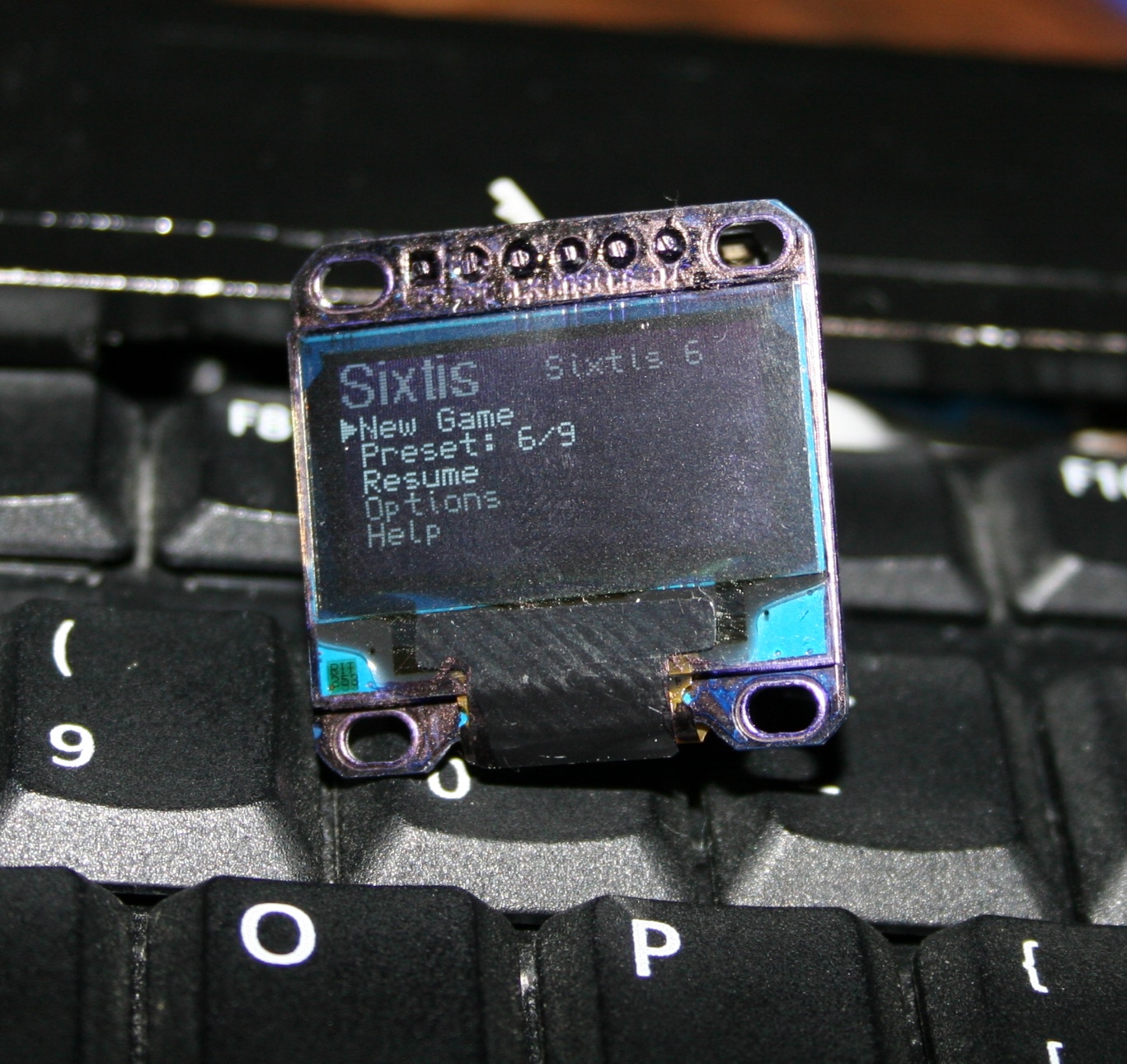
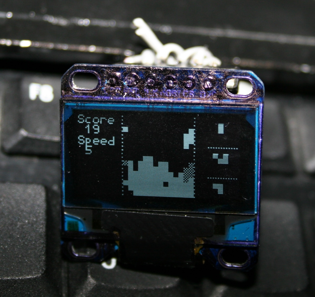
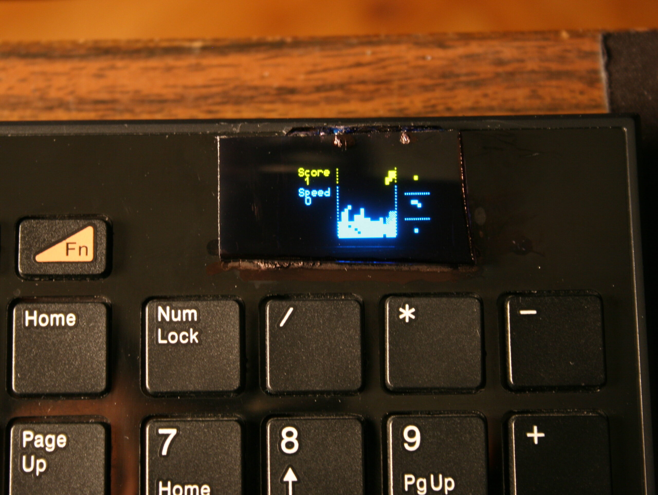
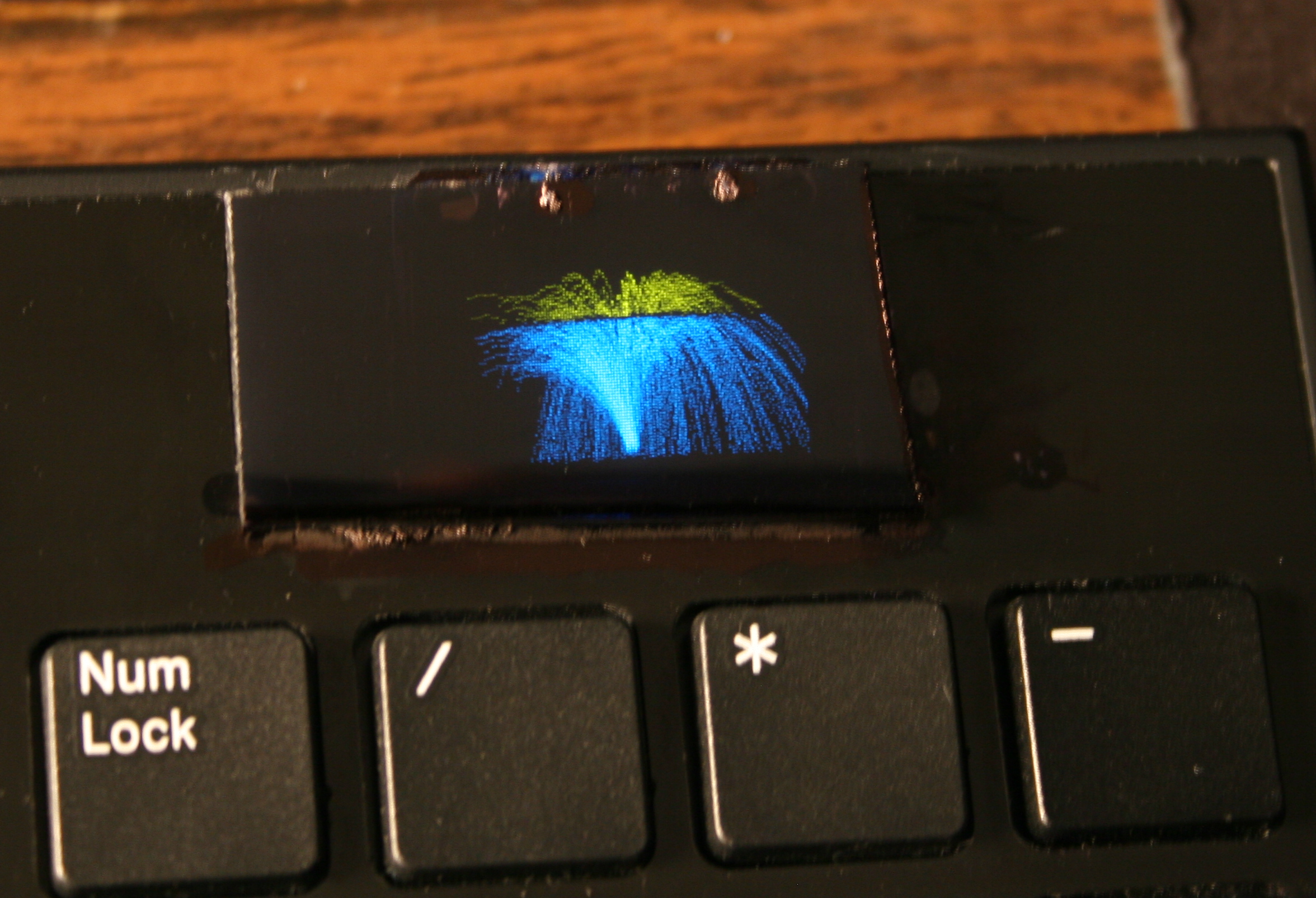
Once I’ve done the useful stuff, I got carried away and implemented several demos on display and even a falling blocks game. I also wrote about it in this forum post.
📂Sources
The code is in my fork here with some more detail. IIRC it can’t build anymore.
⌛Conclusions
It was a bit simpler to start at the time, instead of writing completely my own later on bigger display. Since the display was so tiny I didn’t yet think of drawing all keys on it. And making them rebindable on display, instead of following the way all other FOSS controllers I knew did, that requires rebuild and upload which is way slower.
✅Summary
For reference, here is a table with current status of all my keyboards, since start until present day:
This is an older topic with less information, just for history purpose. If you’re interested see my newer keyboards or the newest ones, with more explanation, own controller and display.
These were my first modifications for keyboards.
They were both done on a Logitech Ultra X Flat, a well done, solid keyboard. Surprisingly different for same model made after 1 year.
✍️Motivation
Originally most keyboards have about 50 gram force needed to press keys, and probably 4 mm distance. After first step of cutting rubber domes the distance is about 1-2mm, the force was about 22 gram for CK1 (bottom) and 33g for CK2 (top). This can also be varied per key.
📊Features
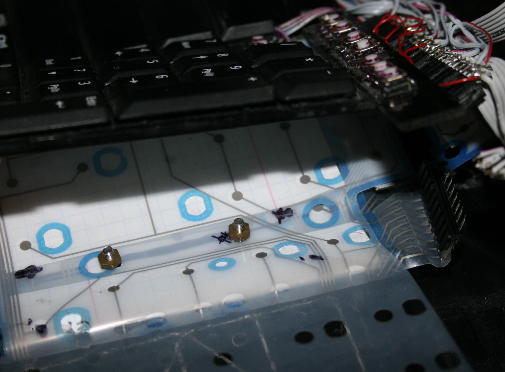
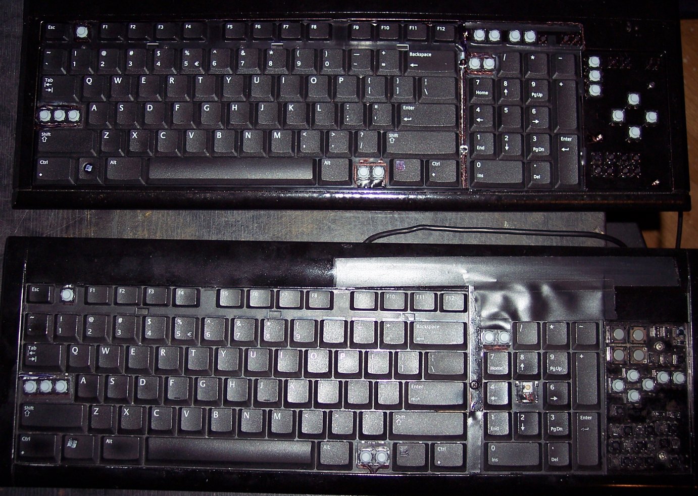
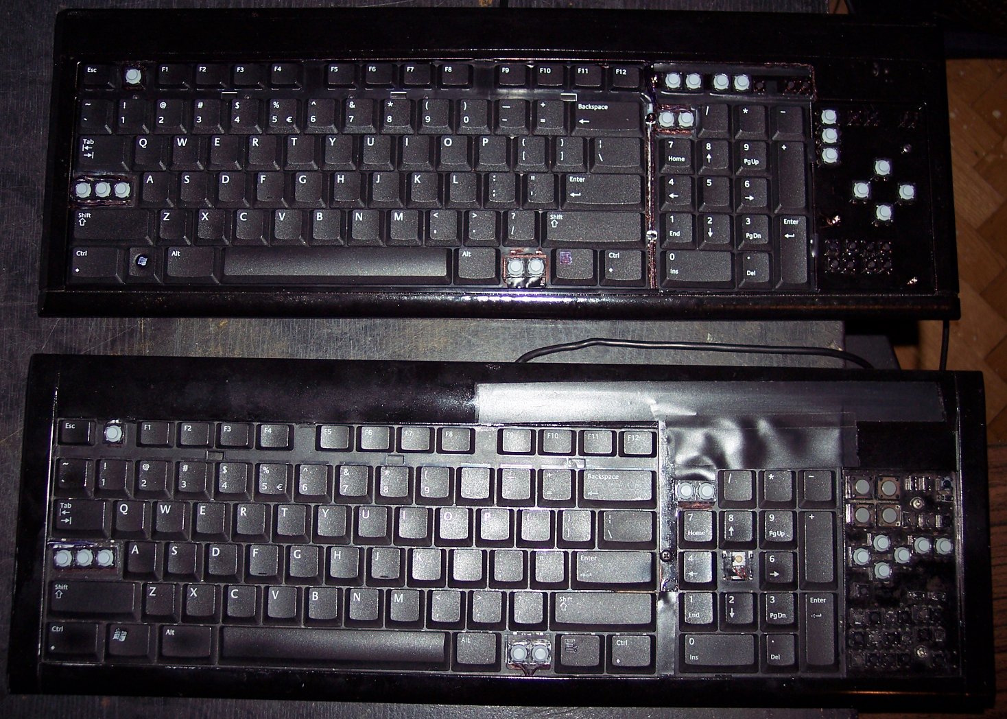
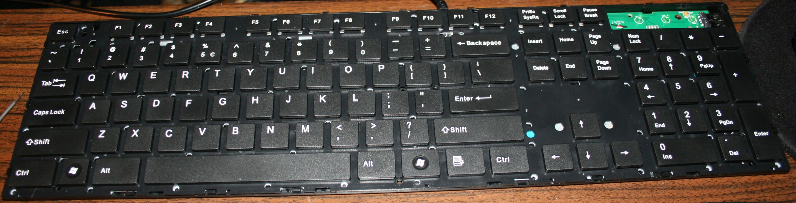
The second step was removing the middle part with arrows. Which I find unnecessary and worse (less keys) than the same from numpad. In CK1 I’ve bent the foil and hid it under. It was risky, but the foil survived. The CK2 was different, it was made from two identical keyboards, thus no need to bend, only cut the metal and foil. That too was risky since the foil could have connections around the cut off part. It was only for numpad, the bigger part had whole foil under.
Years later I modified CK2 further and bent the foil to create CK4 keyboard. And that’s 11 years already, so this would answer any doubts for longevity of such modifications. The number of times I disassembled it, changed something, and put it together is also quite high.
The third step was adding extra keys. Using my oldest program for showing pressed keys and their codes, I figured out that there are more possible keys in keyboard matrix, that are just not connected. So I added them with wires and glued on keyboards. First as regular switches with metal domes, small and hard to press. Later using rubber switches, lighter to press. But turned out to be an even bigger fail since they wear out and stop connecting. They have some resistance too (like maybe 300 ohm) in addition to the resistance of foil traces (maybe 150 ohm). So finally I ended with the smallest metal dome switch I found, with force 0.5 N (50gf). It feels different than other keys but otherwise is good.
This is a guide about my modification of reducing rubberdomes in keyboards to achieve a light press effect. After this procedure keyboards can have much less actuation force (needed to press keys). It is separated from my other projects which describe my keyboard controllers.
✍️Motivation
My motive is pretty straightforward: I want my keyboards to require as little effort to type as possible. And I don’t want any injuries from using my keyboards. These come from fatigue, which comes from more effort to press keys. I found once a pdf writing about this in detail, but don’t have a link. Fatigue also comes from lots of repeated pressing, but this is another thing. I can’t change it (much) if my hobby or work needs it. I do have helpers on display in my controllers (K.C. and K.C.4) showing: total/daily key press count, rate of key presses per minute, a graph with rate over time, and time I’m active typing without a break. So back in 2005 I saw those rubberdomes and thought: “how about I reduce them”. Then there was immediately this problem that they need to be glued back. Well after I did all that, it actually took like 2 weeks to get used to my modified keyboard. I wasn’t sure if this mod will last, but it did. After a while of using, it was easy to understand, that keyboards are really badly and cheaply made and I think it’s just a history thing (just like the thing about this idiotic Qwerty layout), surely not a sum of only intelligent decisions. I’m glad I did this process, and just before writing over 120 pages of my master thesis on this modded keyboard, which now was nice to use and wasn’t meant to injure me. I did a second one for work at some point. I remember once on a keyboard back there was a warning about possible injuries, seemed unreal to me back then, yet it is true, I even once made such mod for a person, who paid and even later thanked me numerous times, because he is suffering from that injury and such keyboard makes less pain to use.
ℹ️Information
Originally most keyboards need about 50 gram force to press keys, and probably 4 mm distance. After cutting, the distance is about 1-2mm, the force gets lower (and depends more on keyboard foil), e.g. 9 to 18 gram for CK5 (but 23 g for CK3, 33 g for CK4 etc). This can also be varied per key (more detail can be seen on pictures (galleries below), but ultimately the lowest 9 g value comes from keyboard’s foil thickness (and those 23 and 33 g values are higher because the foil was thicker in those keyboards).
🛠️Modifications
The first operation I do, is cutting off most of all rubber domes. I aim at minimized key pressing (actuation) force and also travel distance. This makes the keys much softer to press. If pressing needs less effort then it will cause less fatigue. It is simply more pleasant and comfortable. Also healthier, since the risk of keyboard injuries decreases.
The second is glueing them back to keys. It’s required because they are glued to foil (mostly always).
Everytime (except once in 2020) after doing the process, I am using the keyboard myself constantly. Thus if done right, there is no risk of any key failure.
📜History
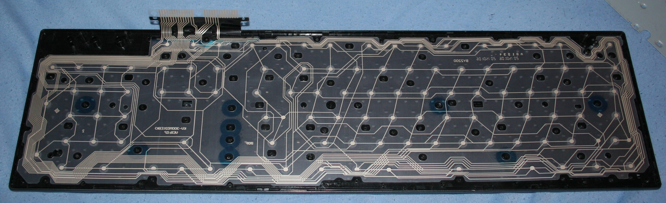
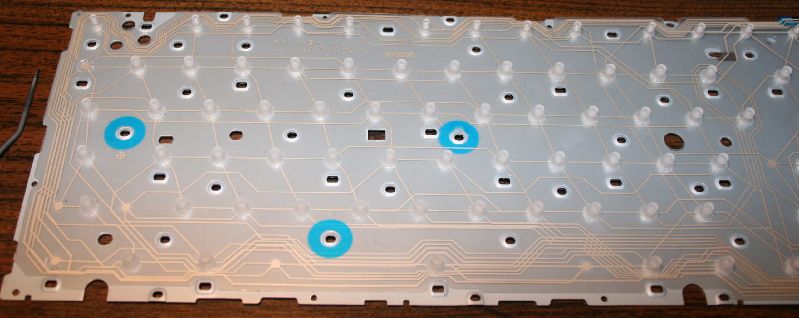
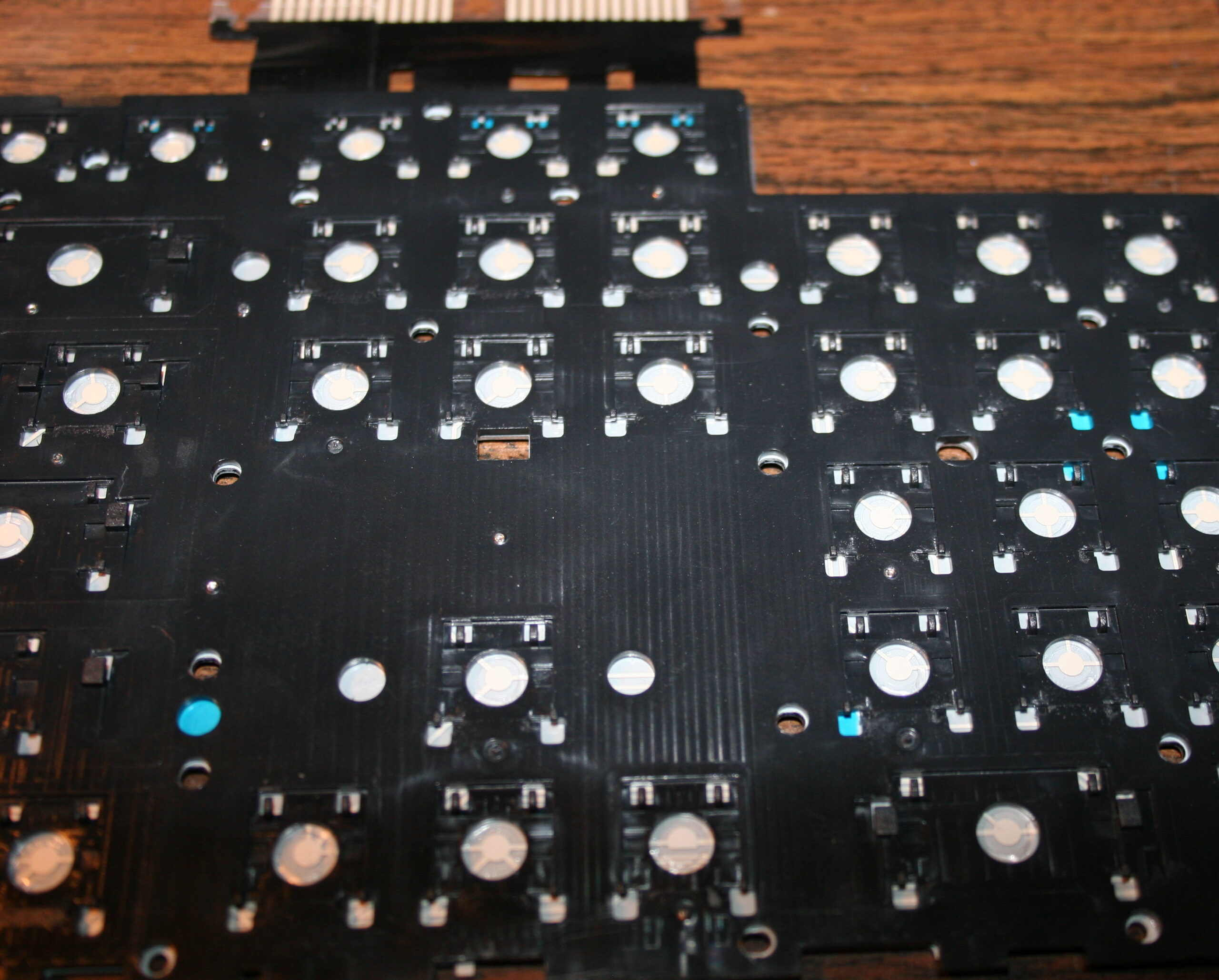
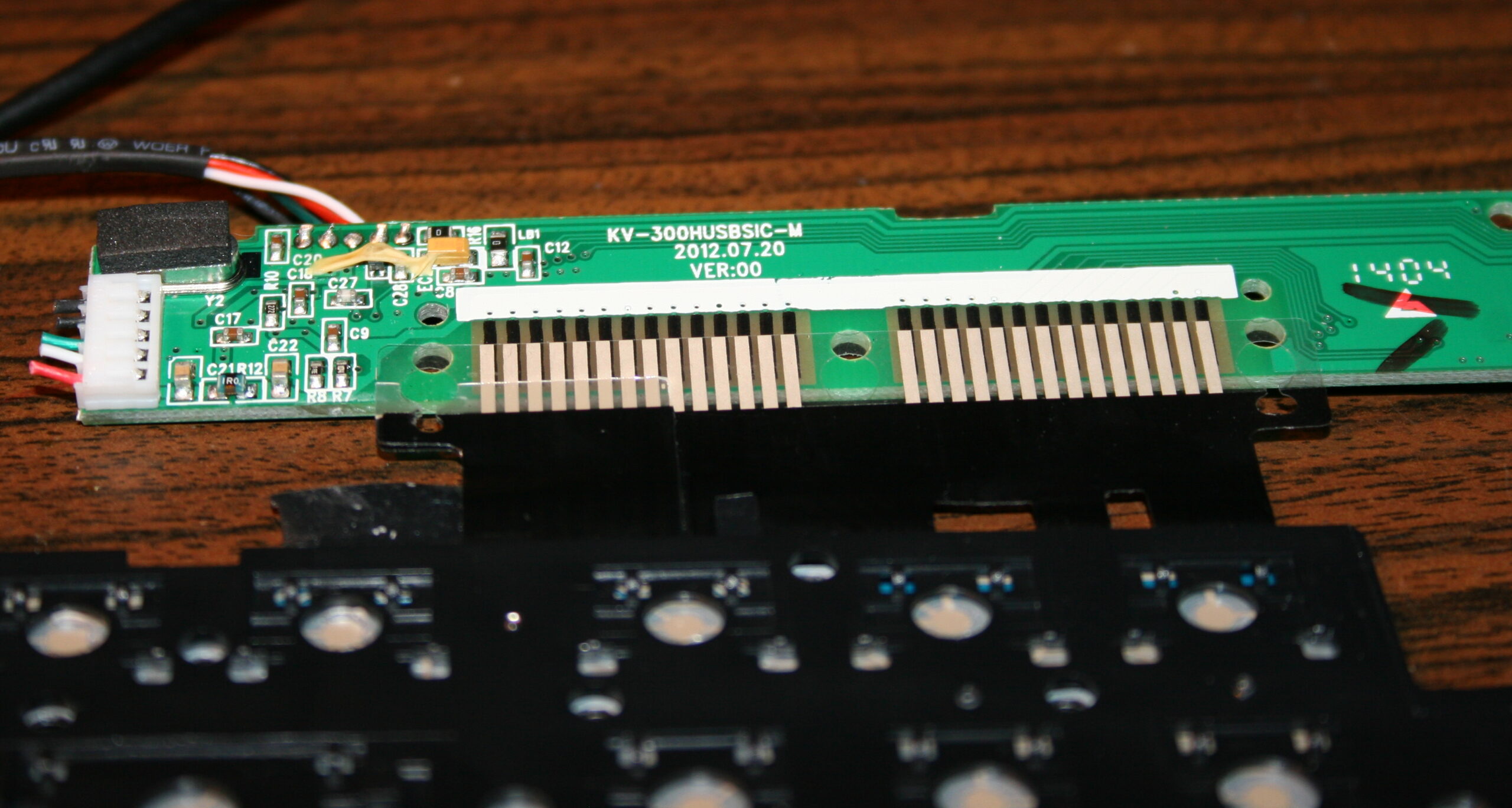
I already did this first on my two oldest keyboards in 2005 and 2006. Then in 2015 for this keyboard (originally A4 Tech KV-300H) named CK5, and again later in 2020 (another same keyboard) making the process the video. Next for CK3 and CK4 in 2016, which later became CK6 and CK7, and CK6 became CK9 with KC4 in 2020.
▶️Videos
Video guide showing the process here, for just a few keys. Another video of testing force with weights after.
🪛Steps, guide
Steps needed, shown in video:
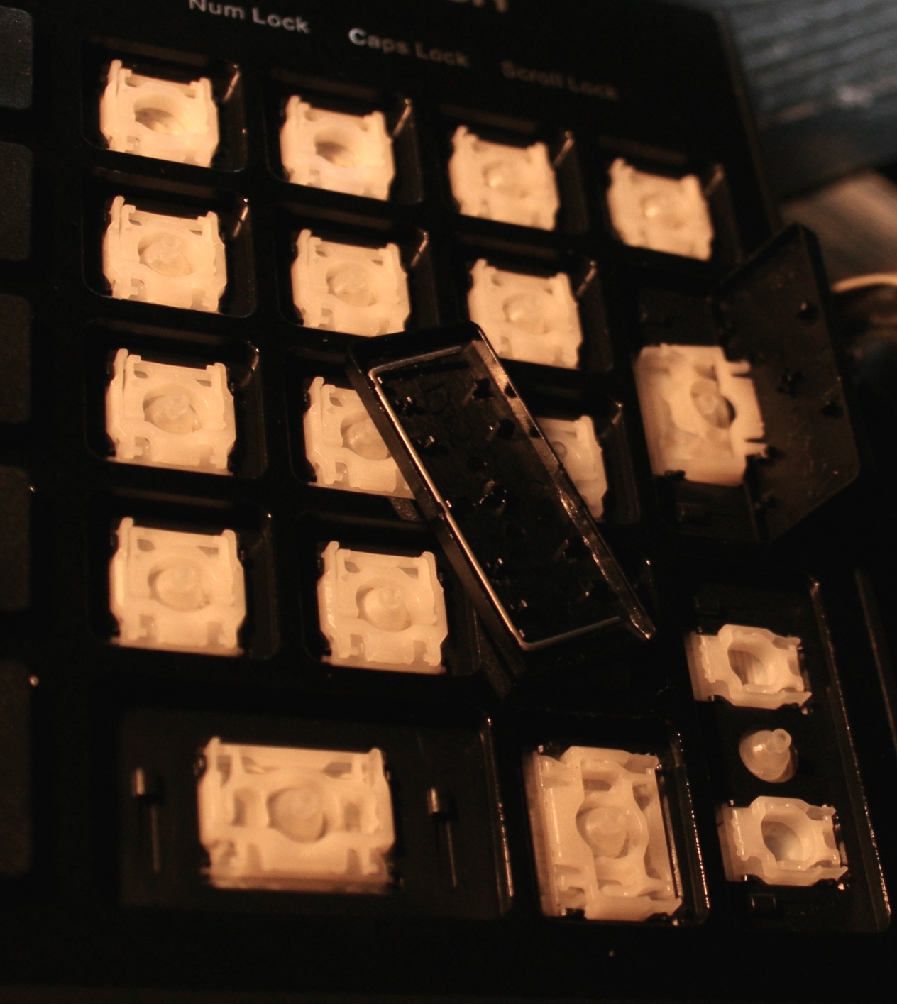
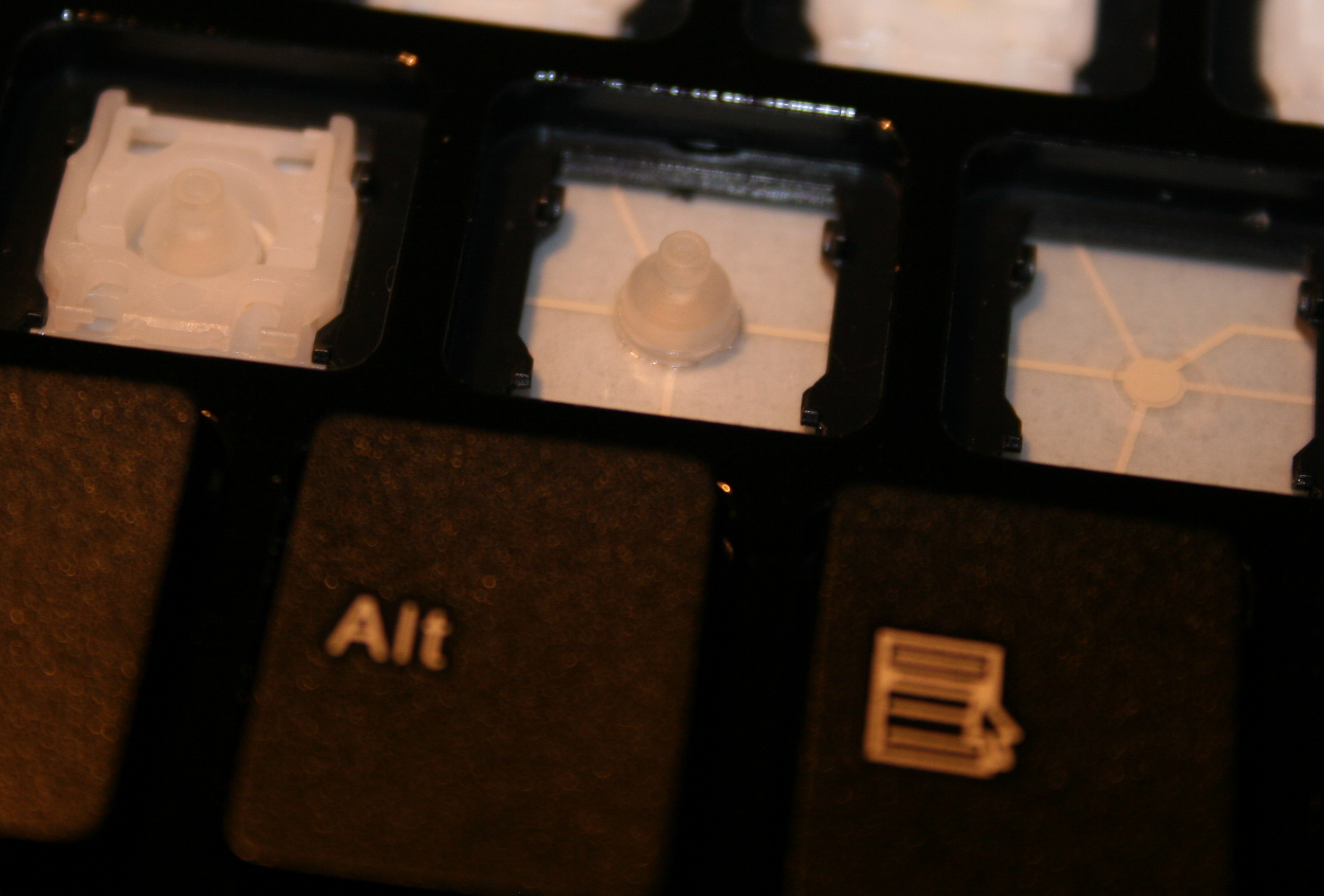
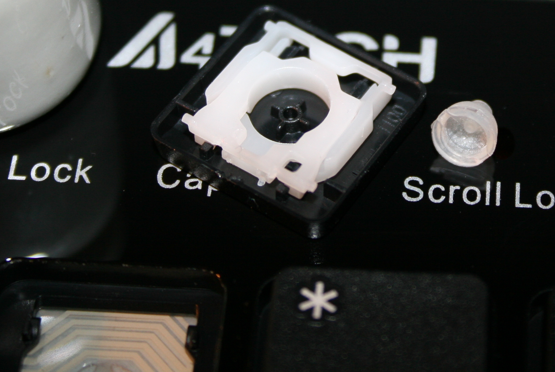
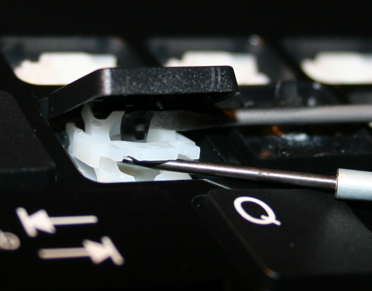
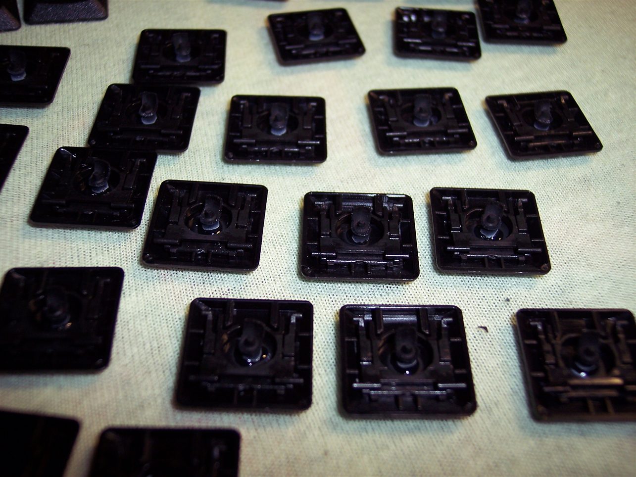
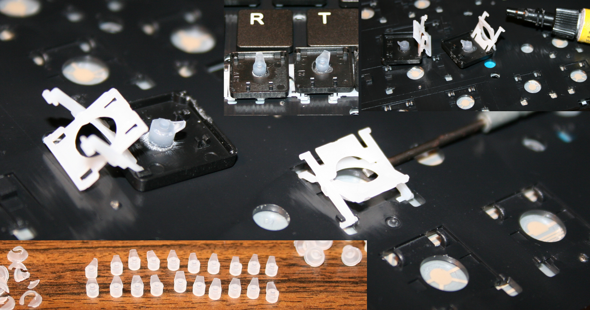
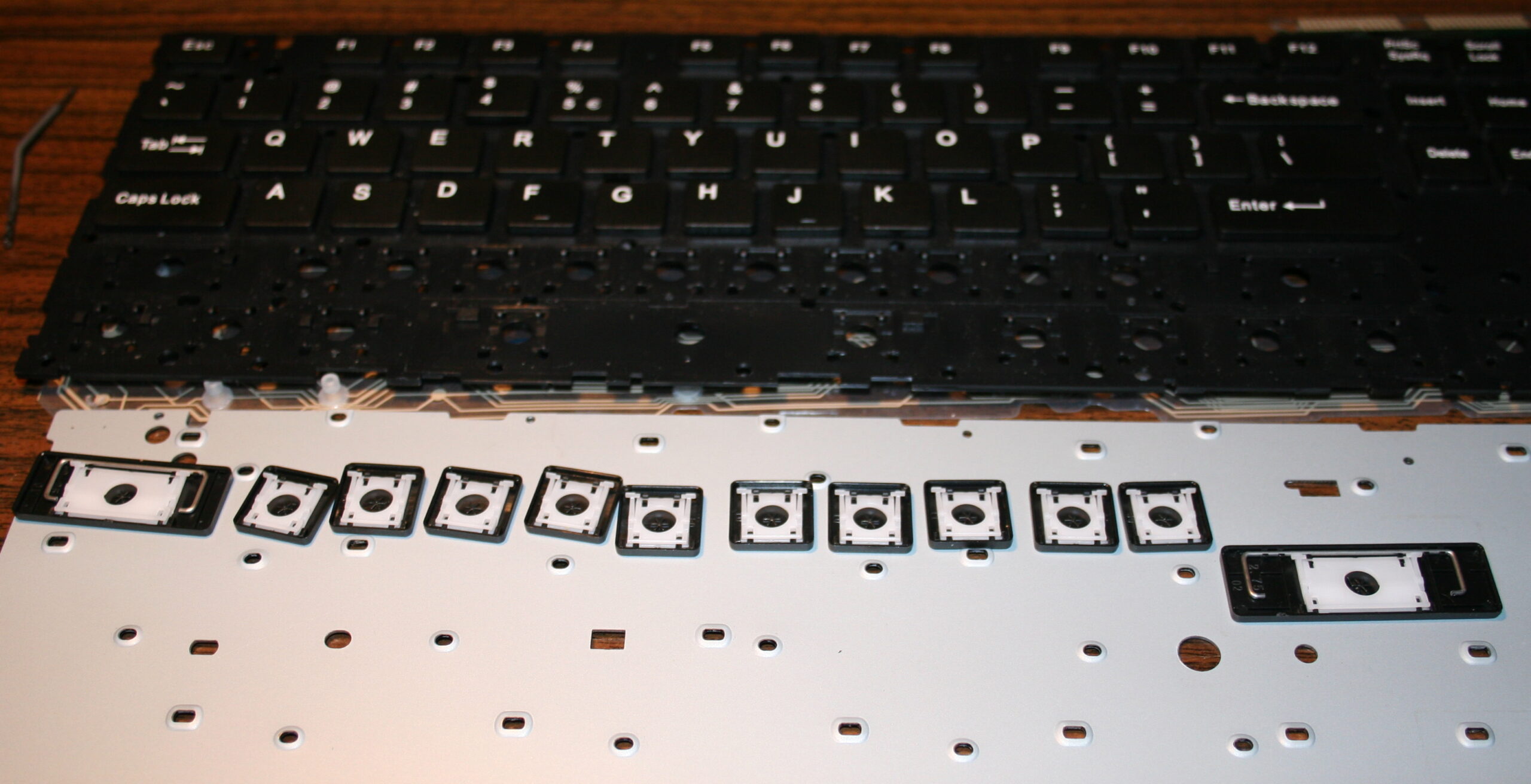
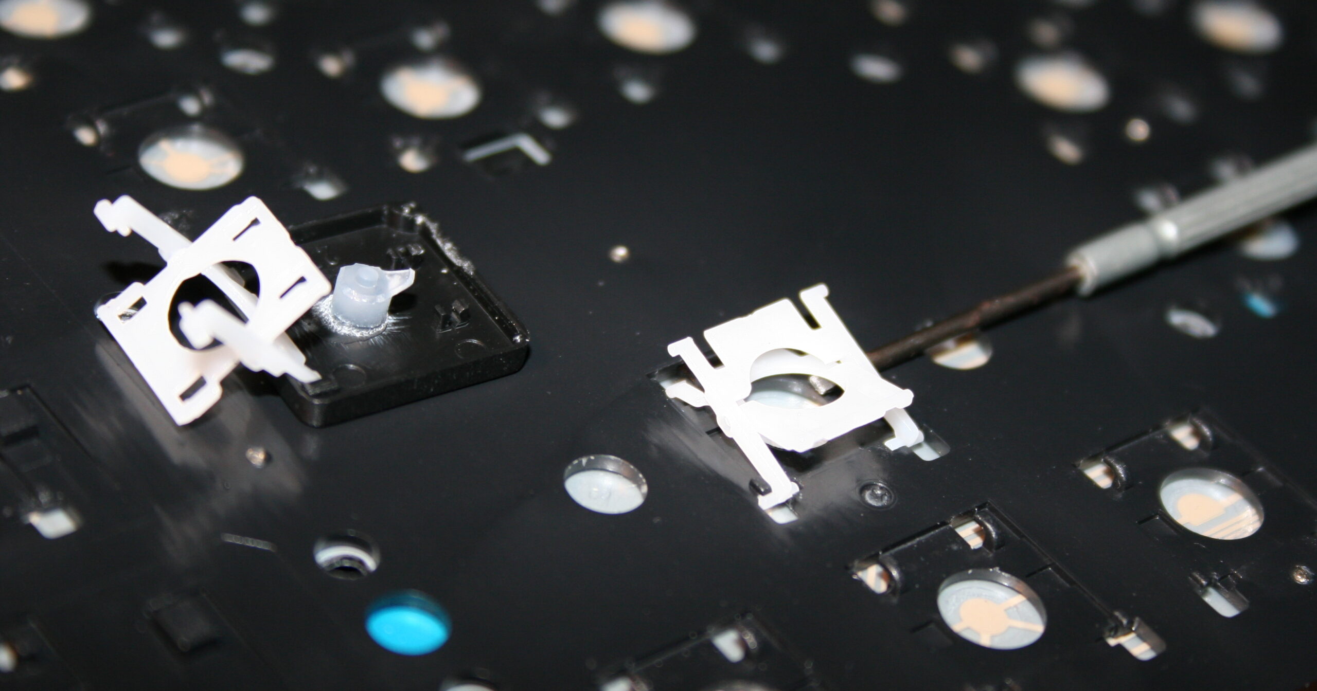
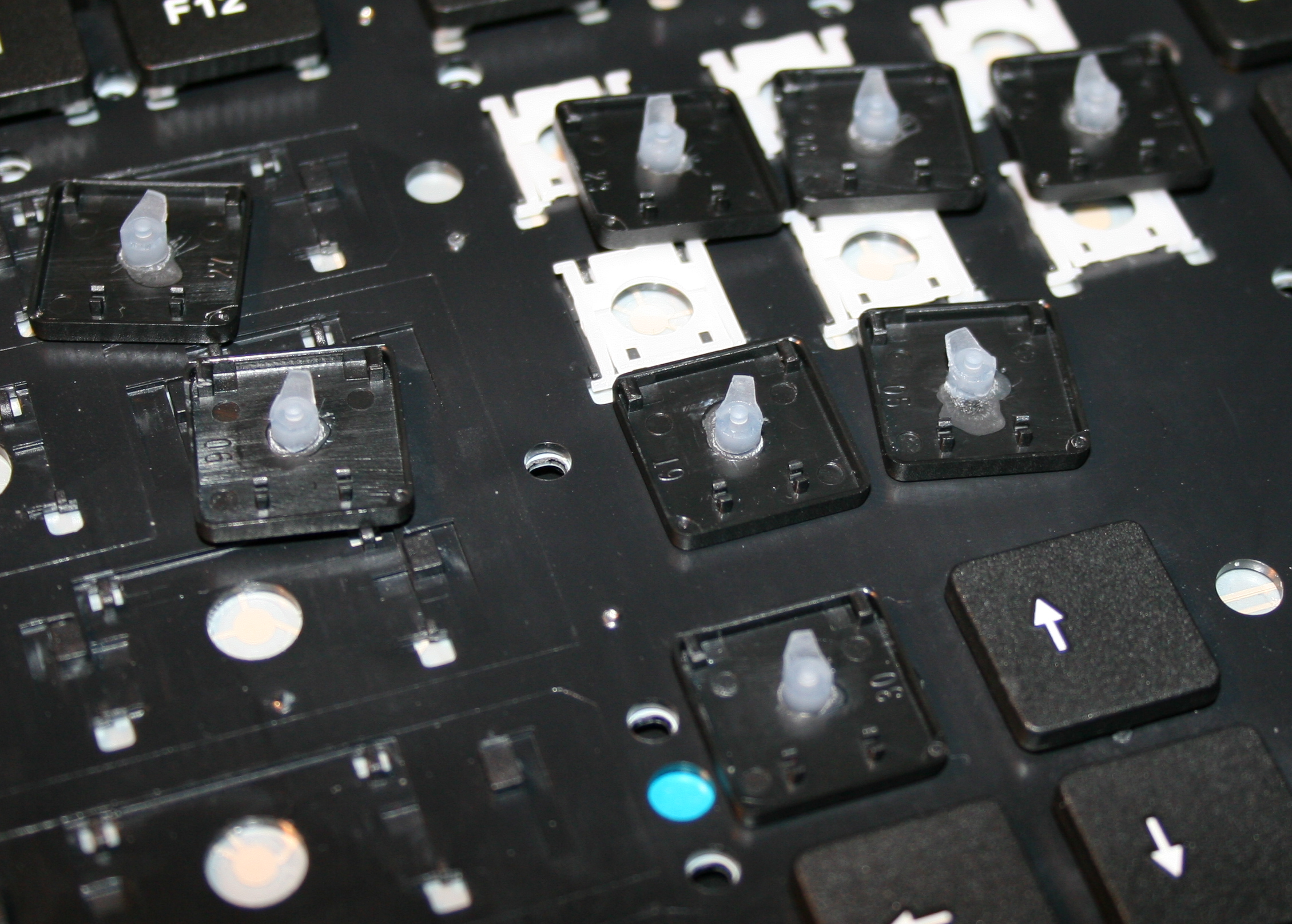
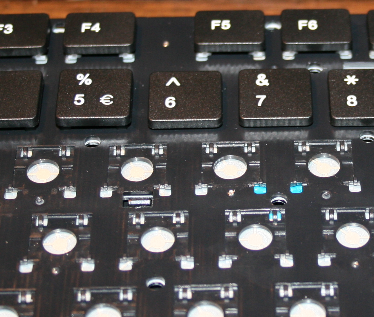
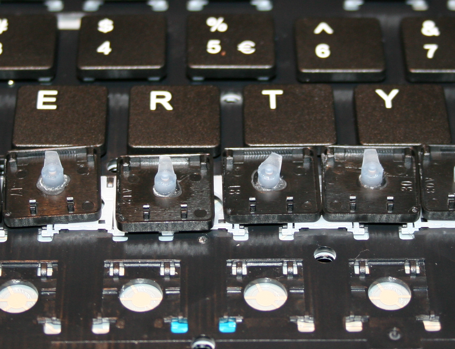
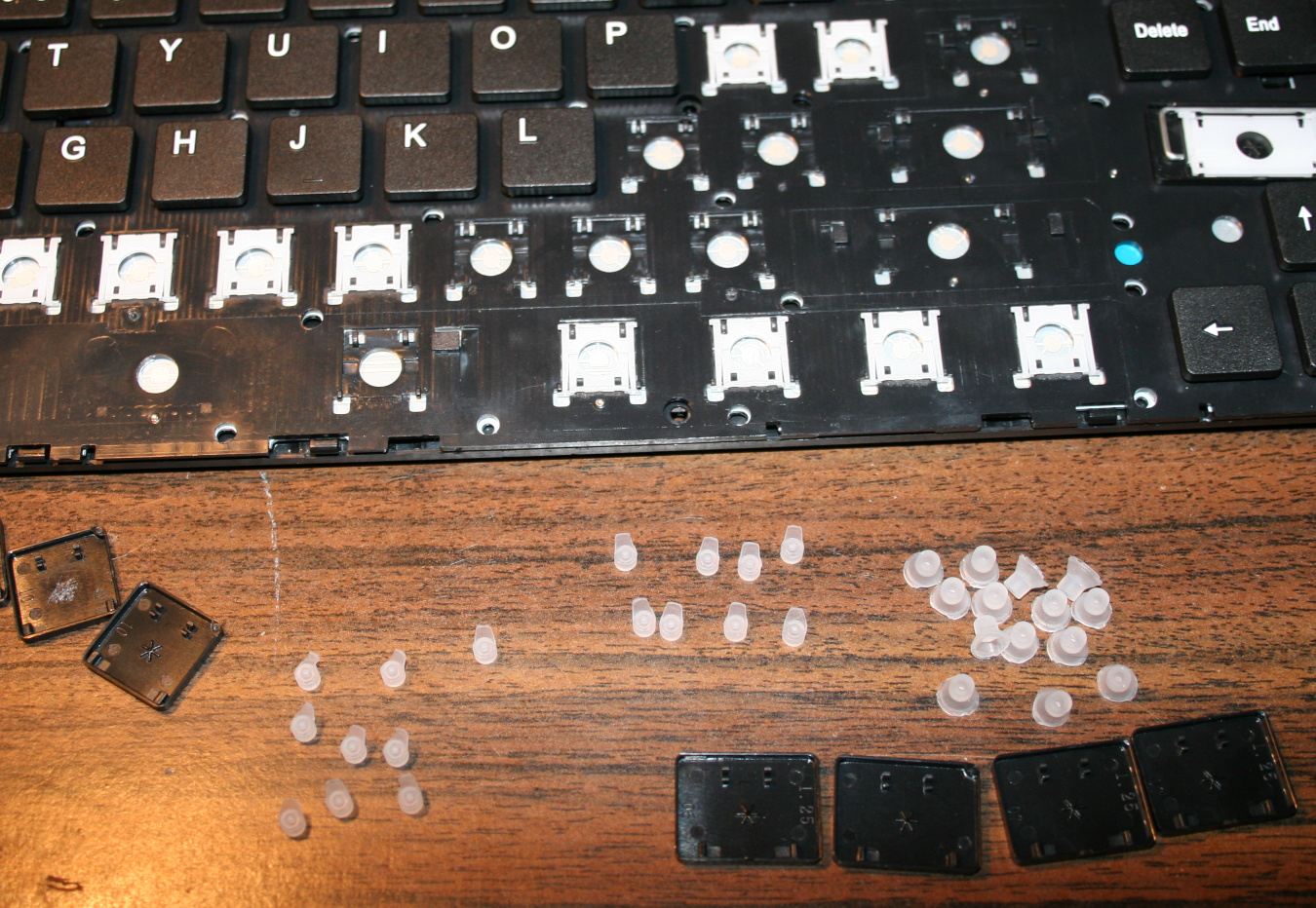
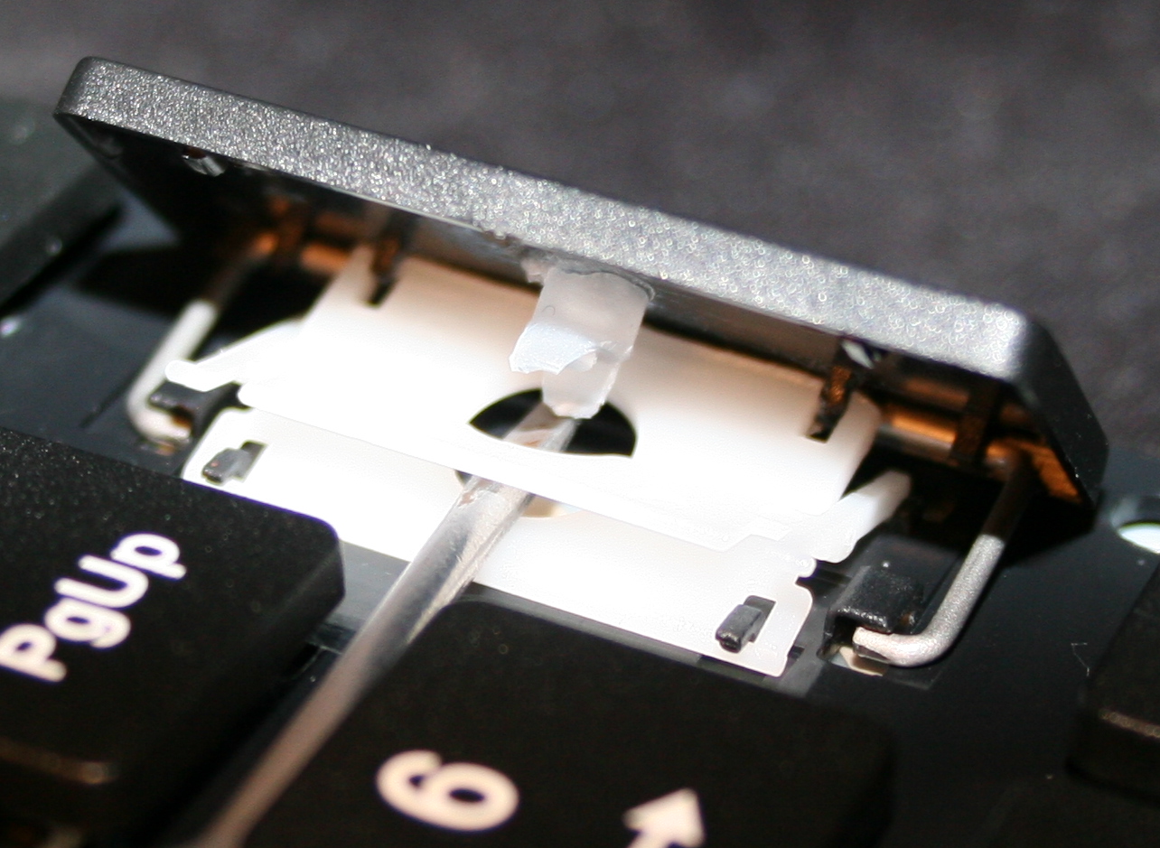
Getting keys off from keyboard, using a tiny flat screwdriver. Pushing gently (but firmly) and leveraging tiny screwdriver in 1 corner, to pop the key’s scissor lift (white) out of its “half socket” from keyboard (not from top of key).
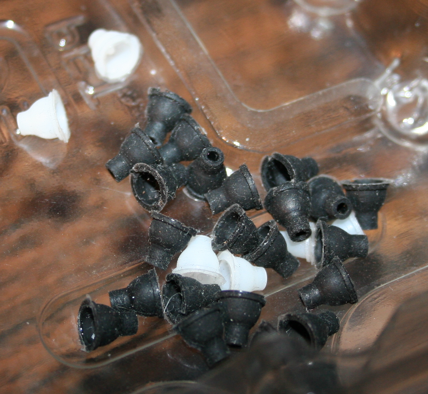
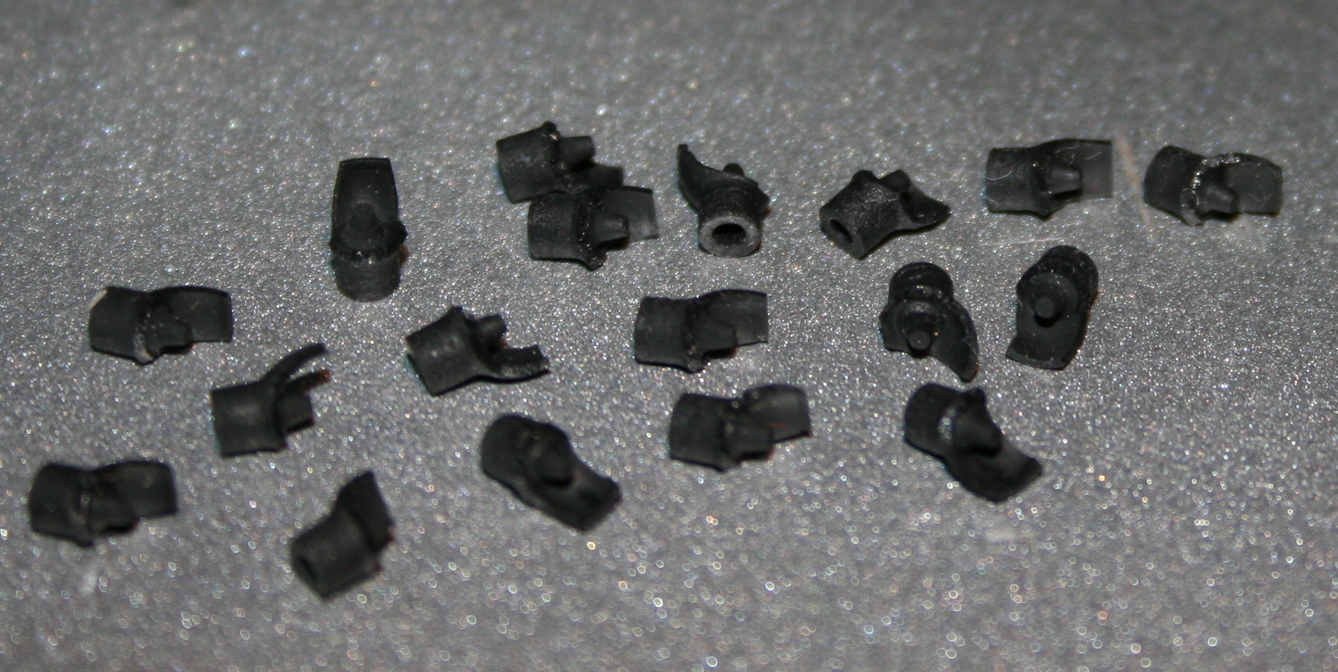
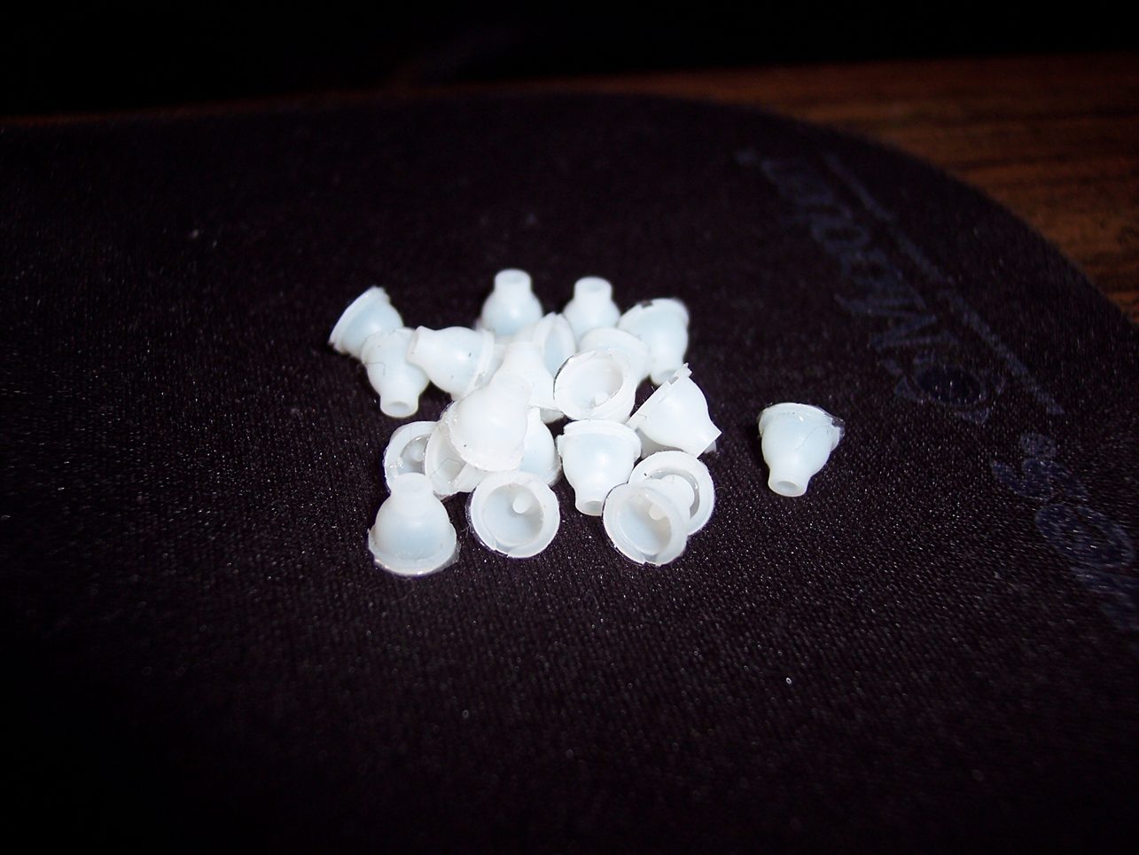
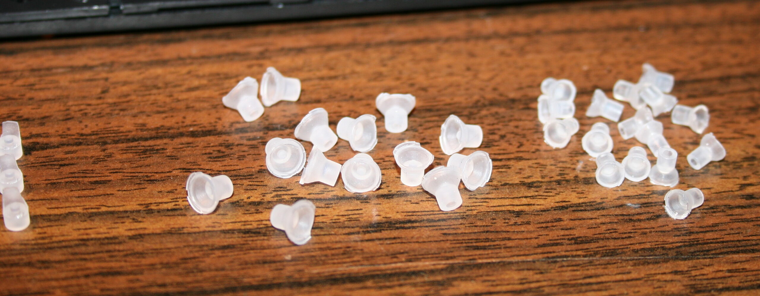
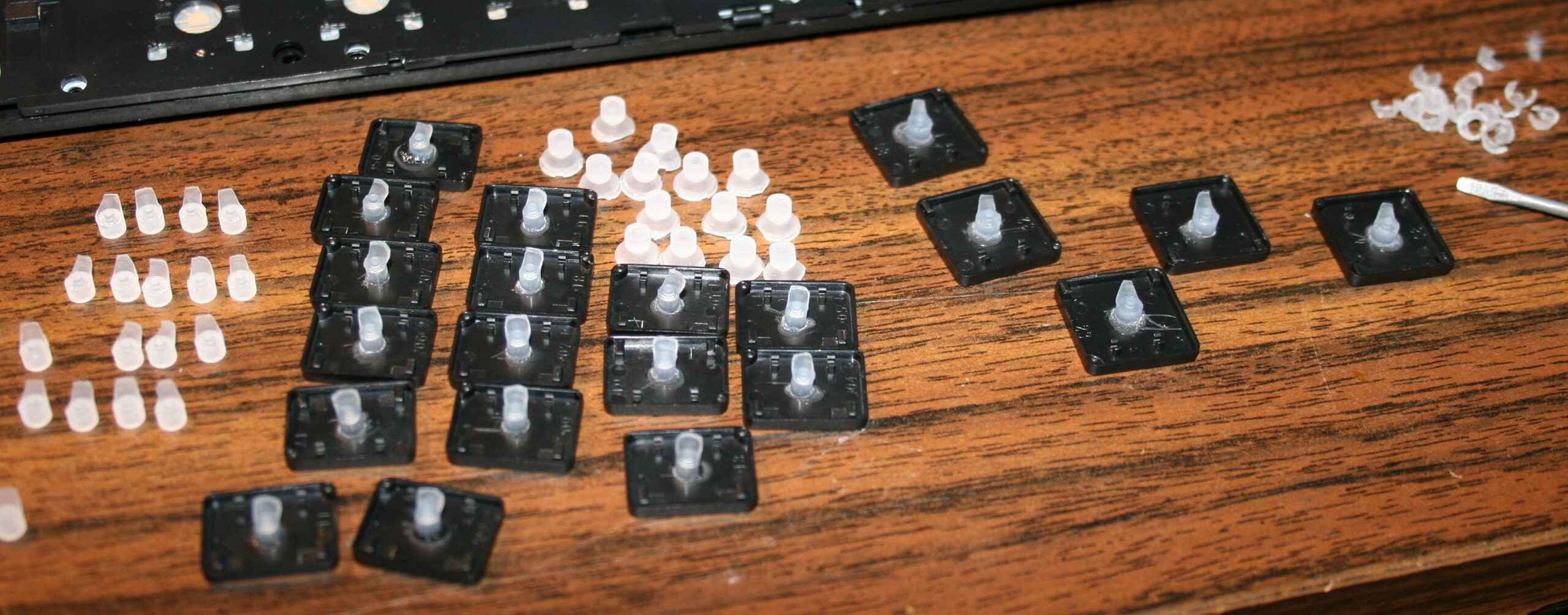
Getting rubberdomes off from foil, using just fingers, pinching with force. In laptop keyboards, the rubberdomes are separate and small. But on old very cheap keyboards there is 1 big rubber piece with them all. I didn’t try modding them.
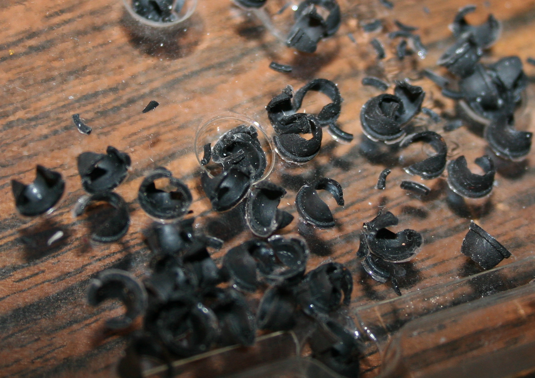
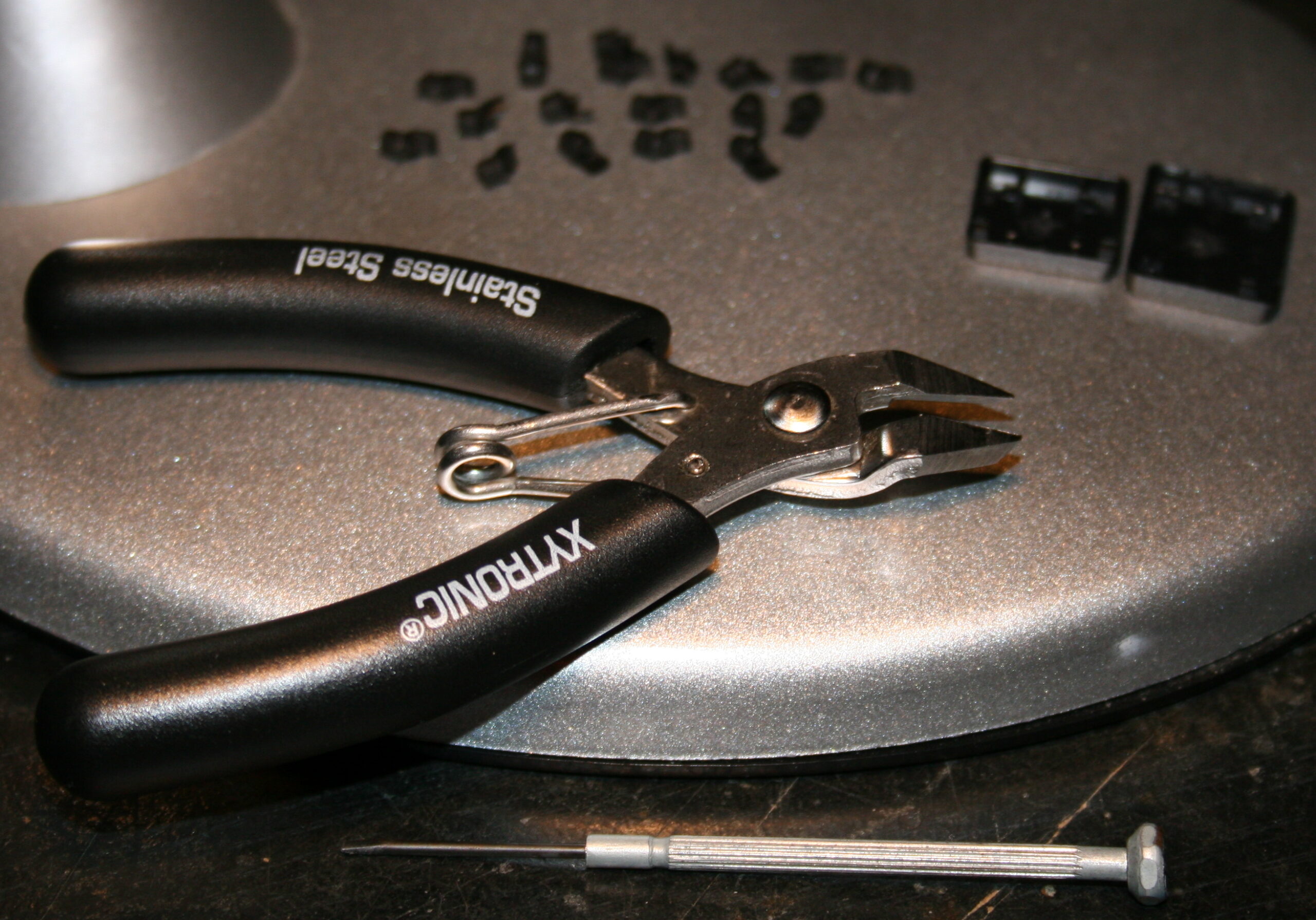
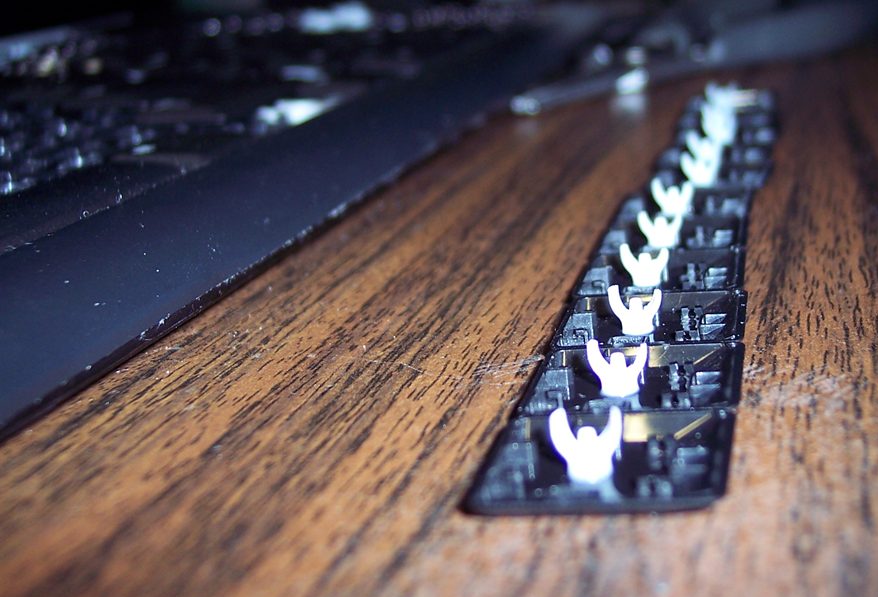
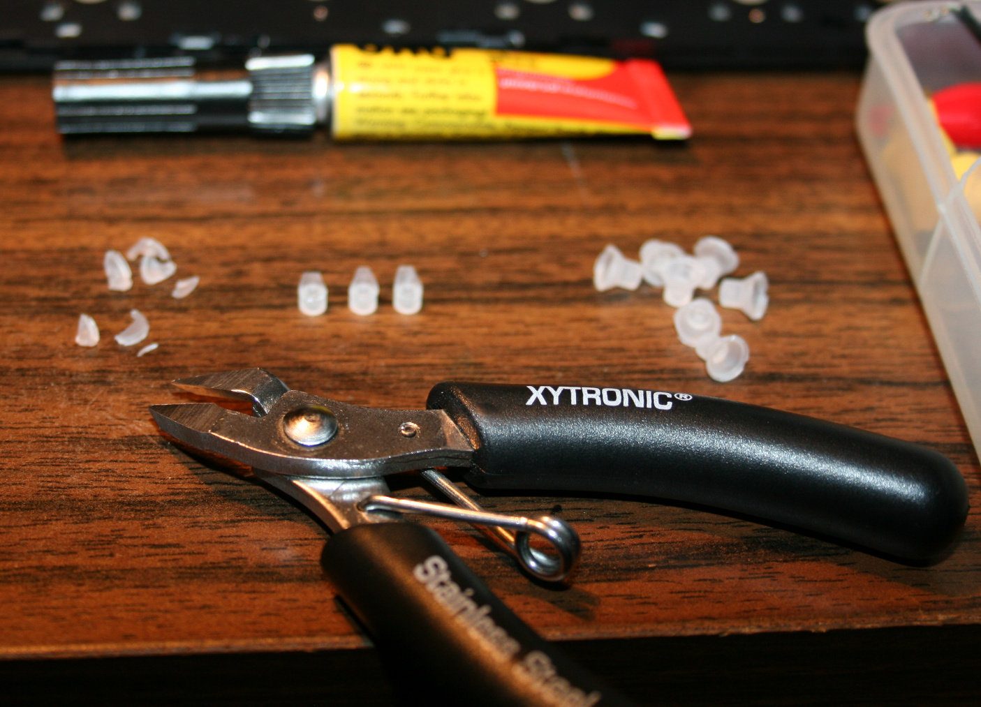
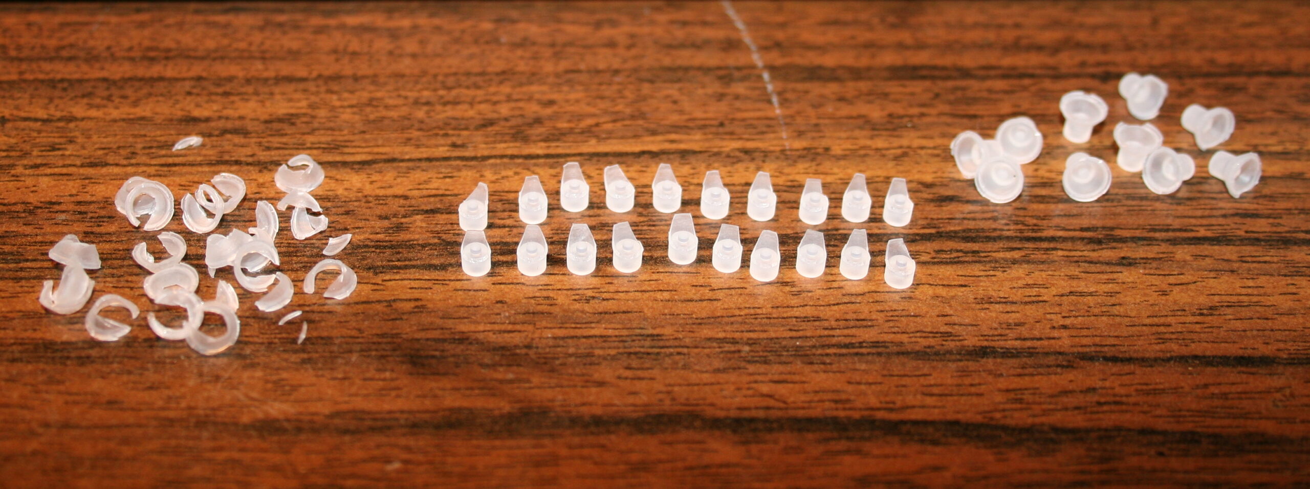
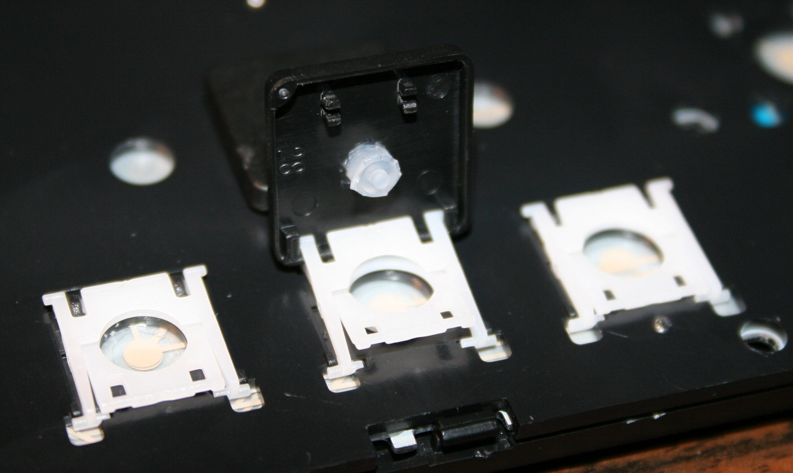
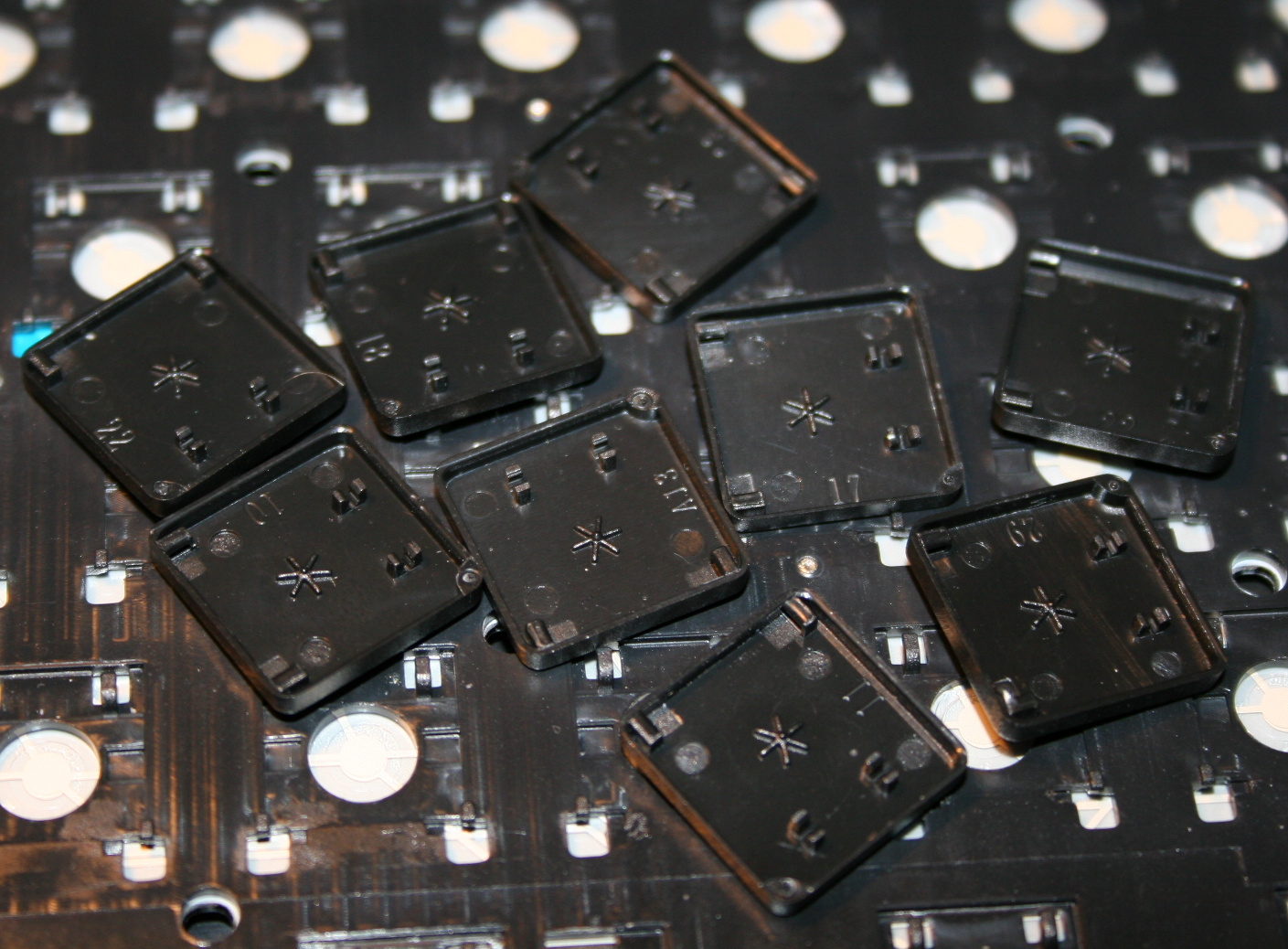
Cutting off rubberdomes, using small side cutters. The more you cut off the less force and travel. But caution for bigger keys, especially Spacebar, they need a bit more rubber width left (or in 2 places) for same force, because they are heavier. I did reduce modifiers (Shift, Ctrl, Alf) keys and arrows completely, without that short supporting width, they’re just resting on keyboard foil, this gives only 9 g force. Value depends on foil, and not at all on rubber because there is none left. For most keys usually few mm width and height (3-5 mm or so) is holding it above foil.
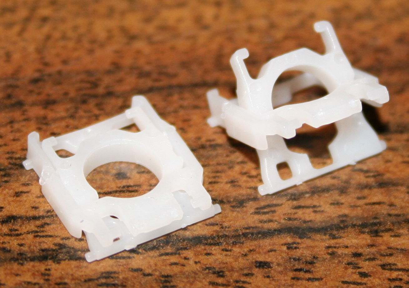
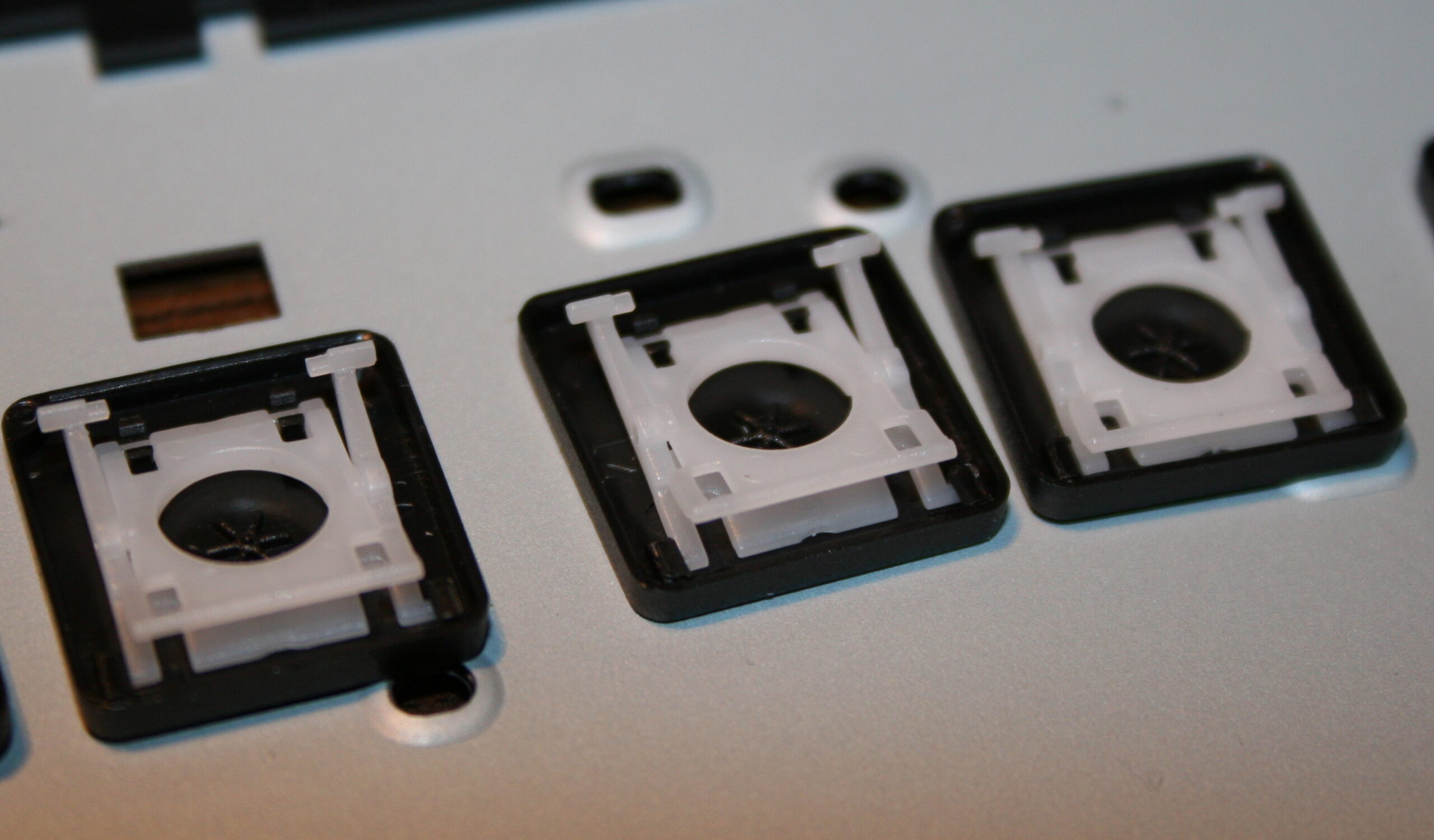
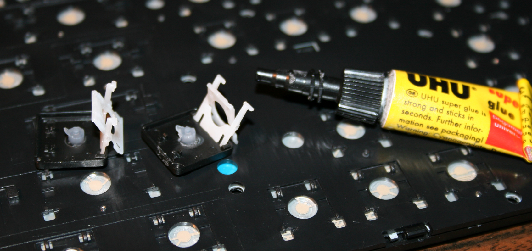
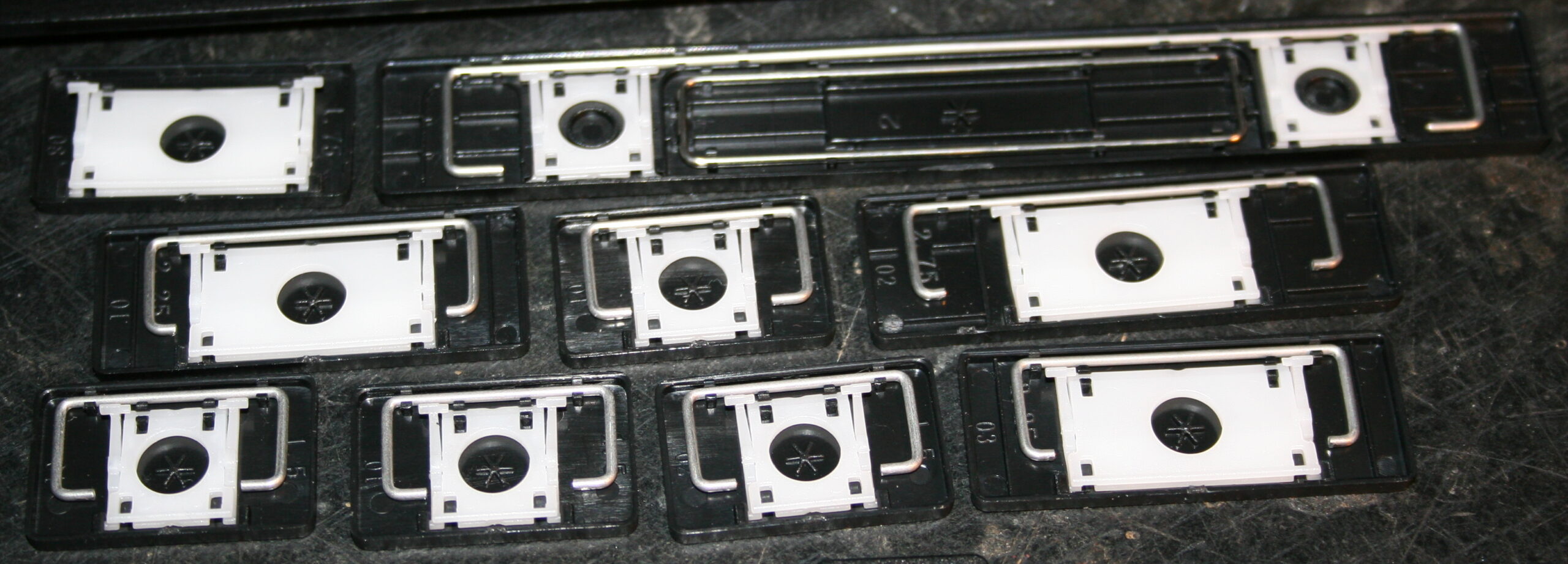
Removing scissor plastic (white) from key (black), using a tiny flat screwdriver.
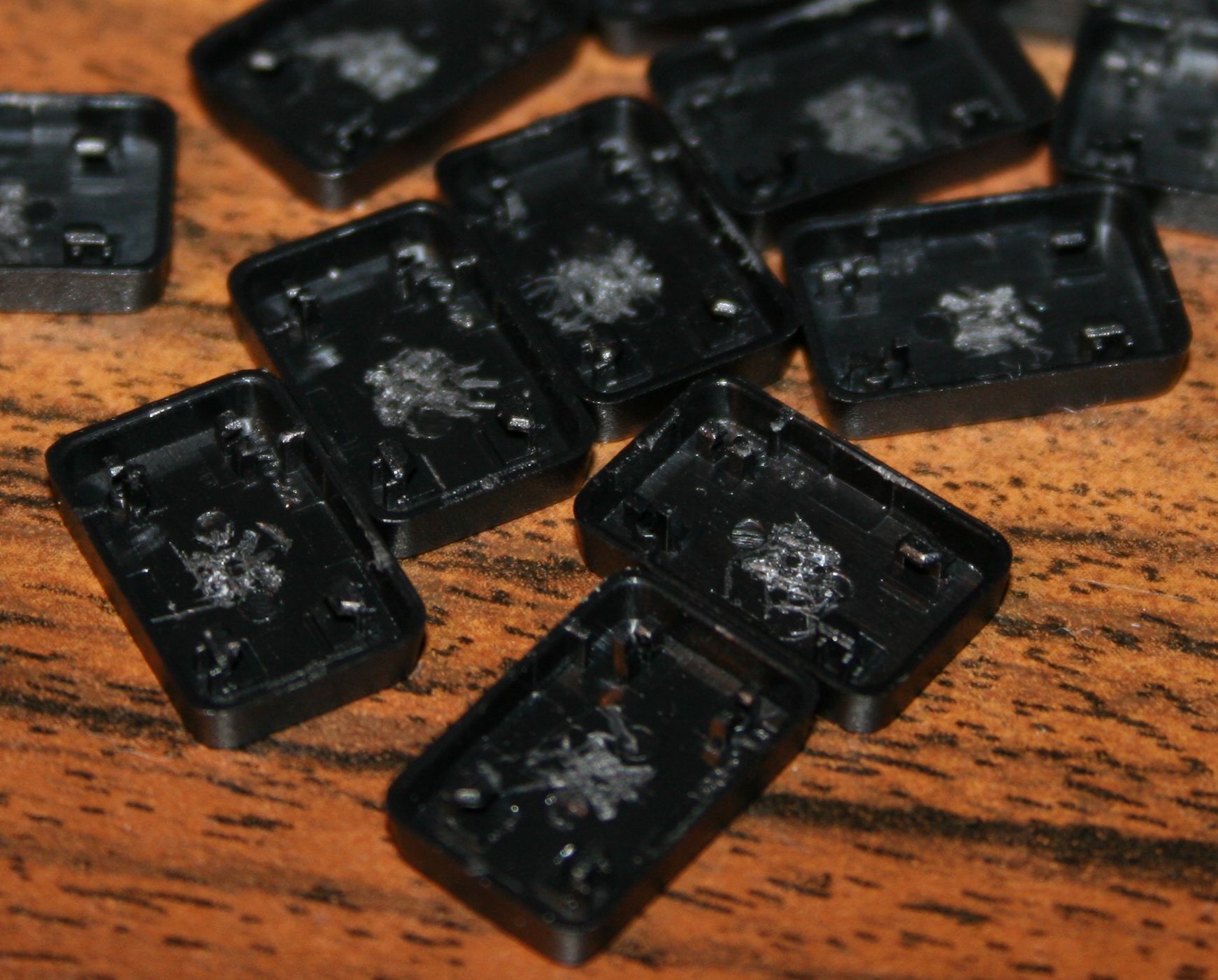
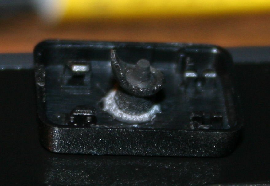
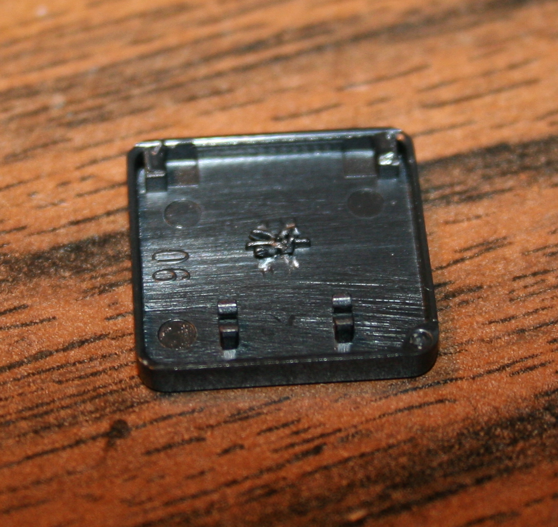
Optionally (if present) scraping that (stupid) star * pattern made on keys, to be flat. Can be scratched with cutters or screwdriver, may be even better so for glue.
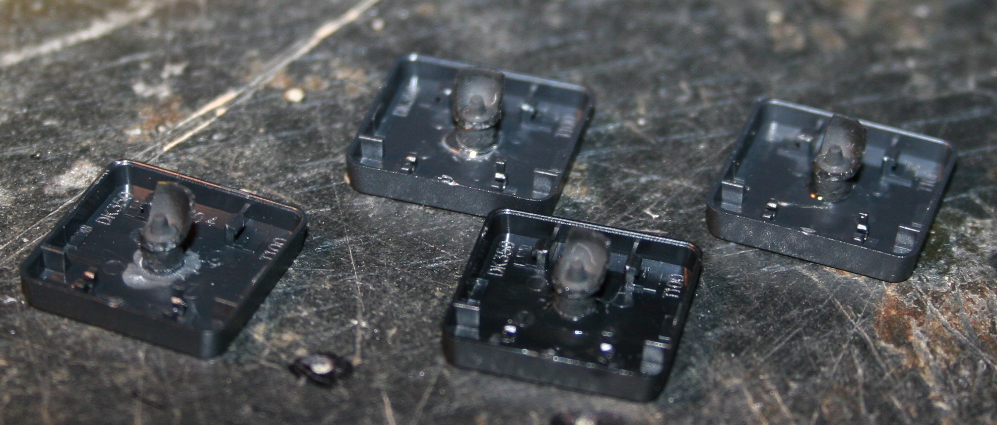
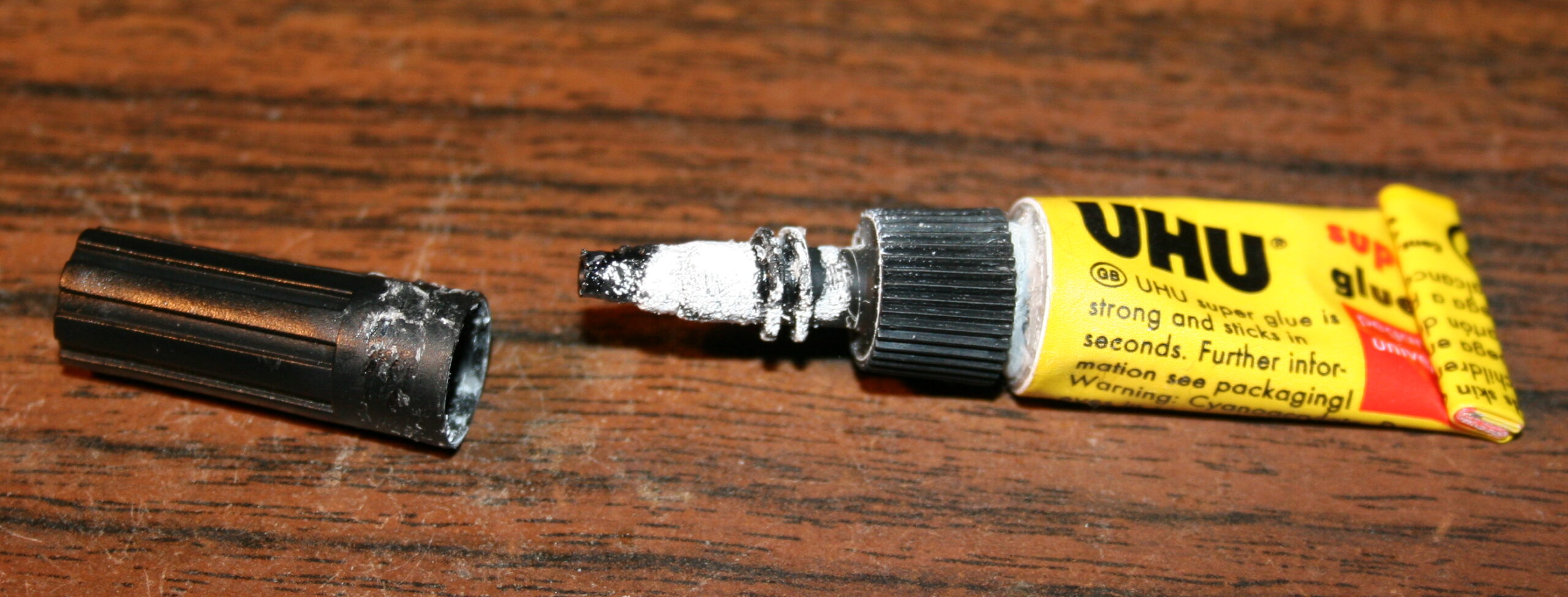
Glueing (reduced rubberdomes) back to keys, using any superglue (cyanoacrylate based). Holding with tweezers or smallest pliers for a few seconds.
Waiting (best about 1 minute) until glue gets solid and ready. On video I’m actually making this too fast. Depends also on how good or fresh (after opening) the glue is.
Lastly mounting keys back, rather easy after knowing how the scissor keys work
Repeating for each key. Unfortunately it is really boring and tedious. Took me about 2 days for 1 keyboard.


