Category: Electronics📱

  • 2016 Keyboards CK3,4 ⌨️

    2016 Keyboards CK3,4 ⌨️

    ⏱️Overview

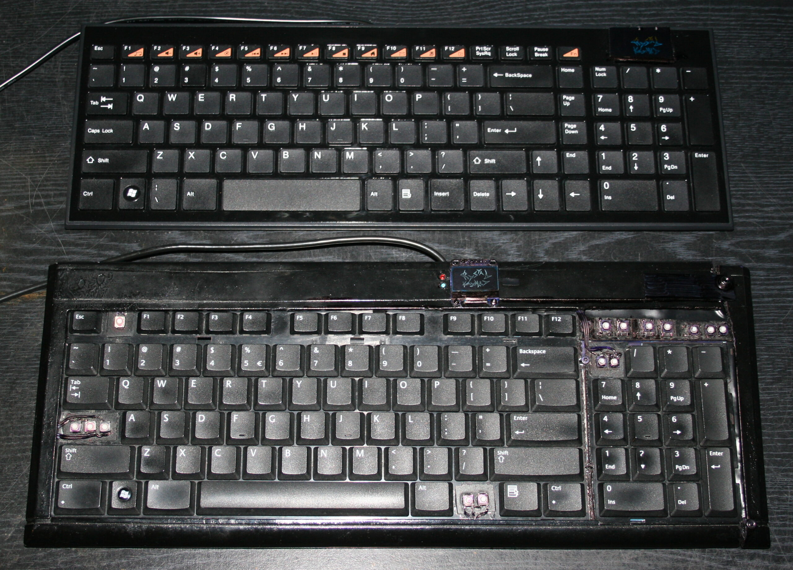
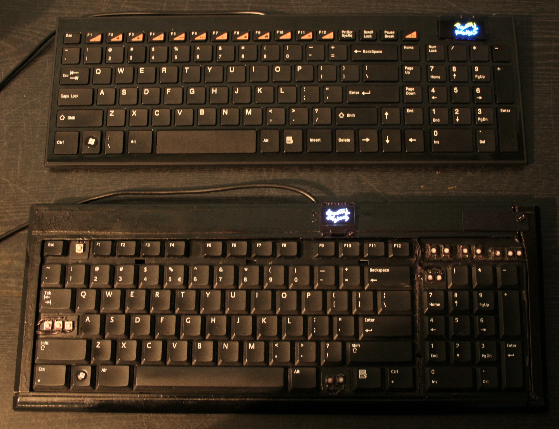
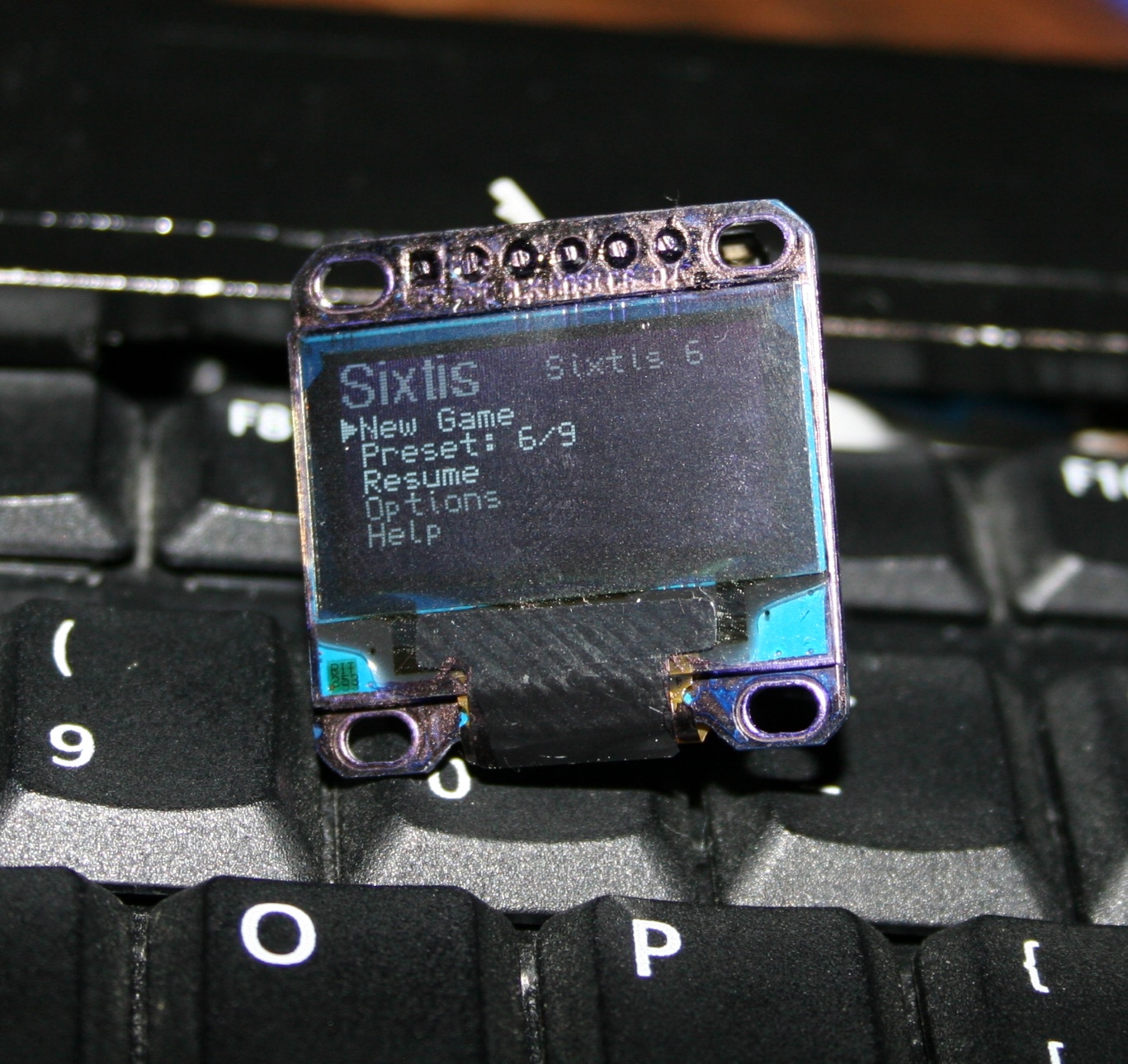
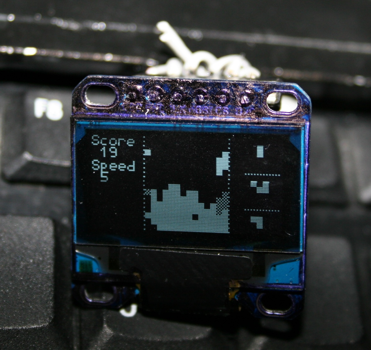
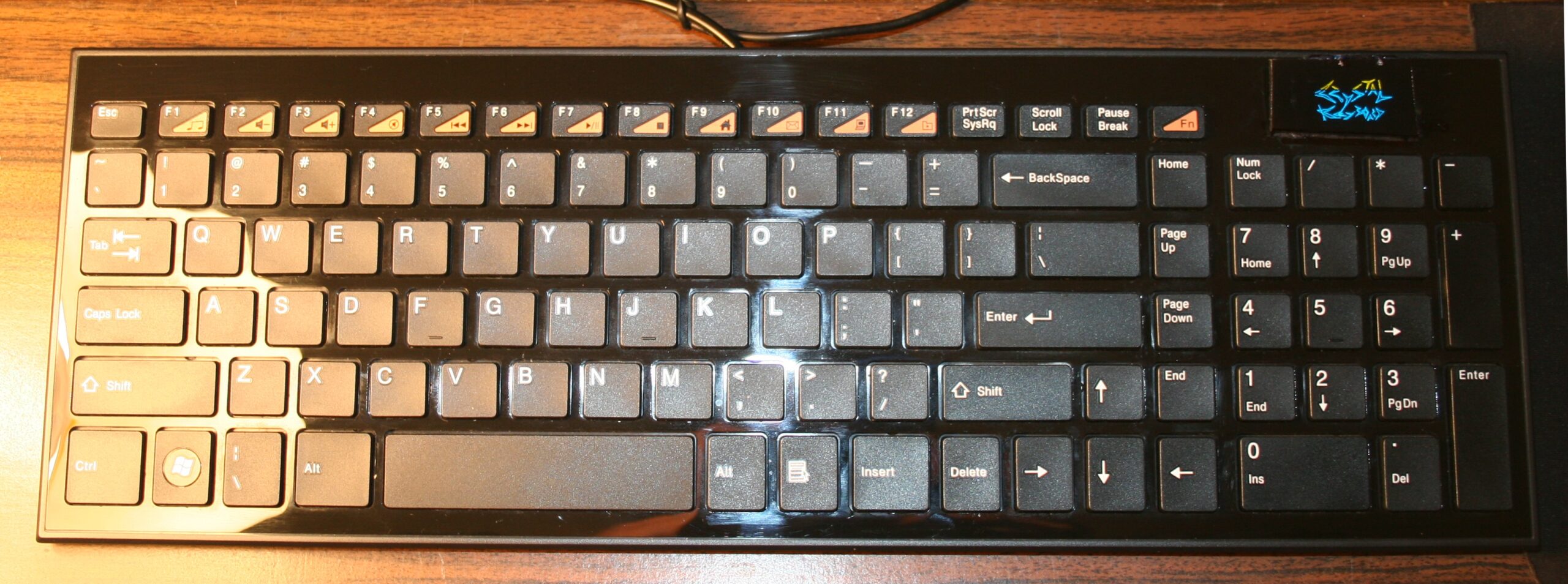
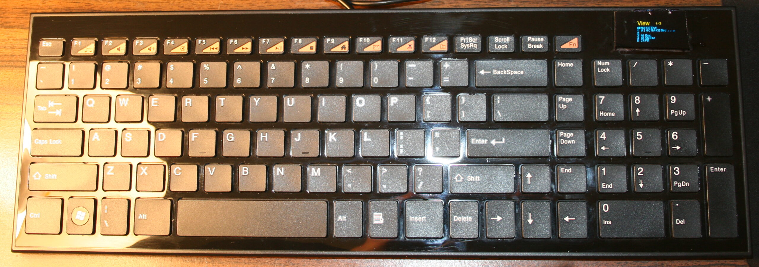
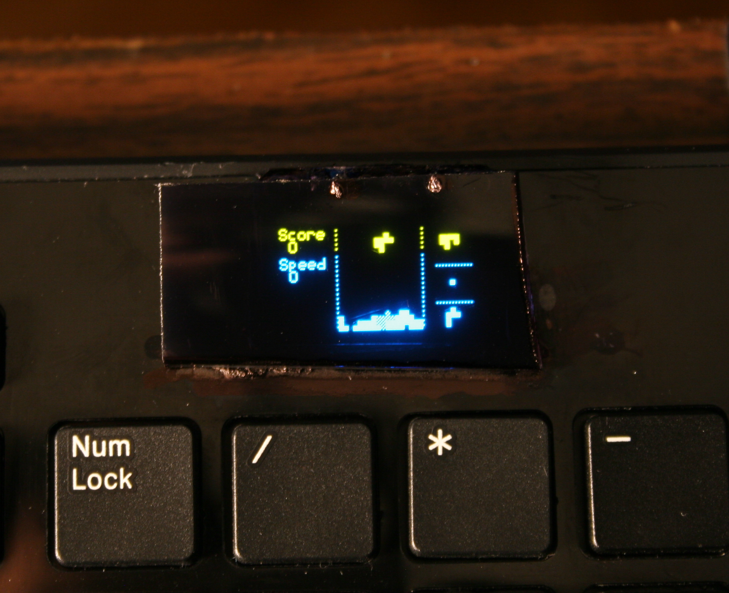
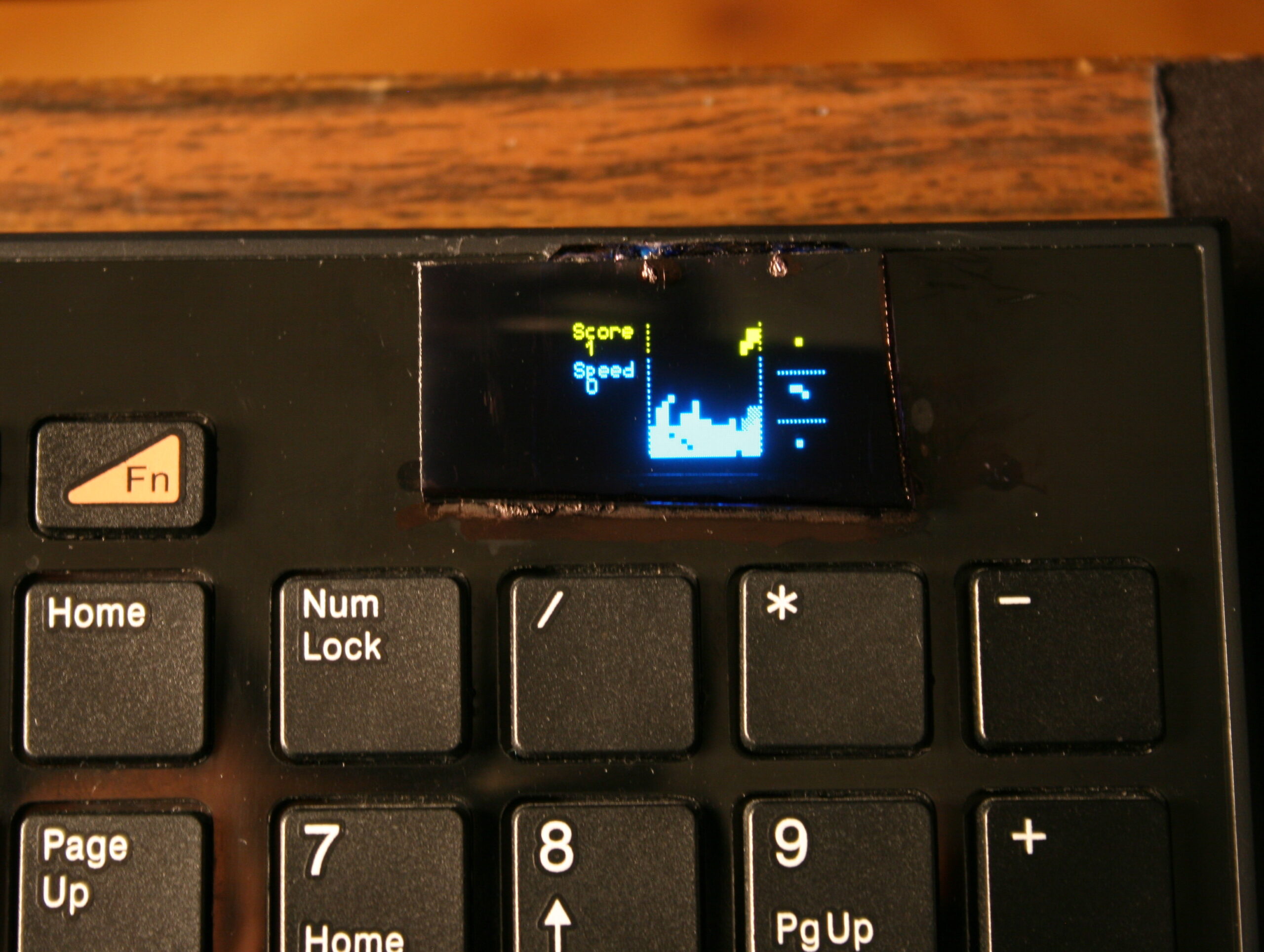
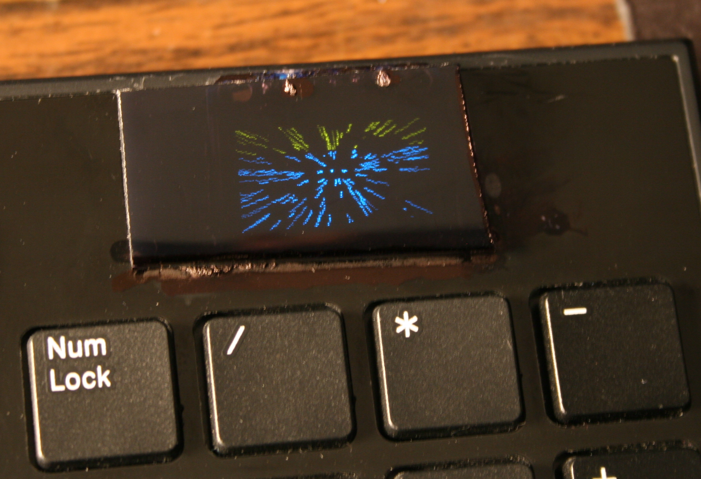
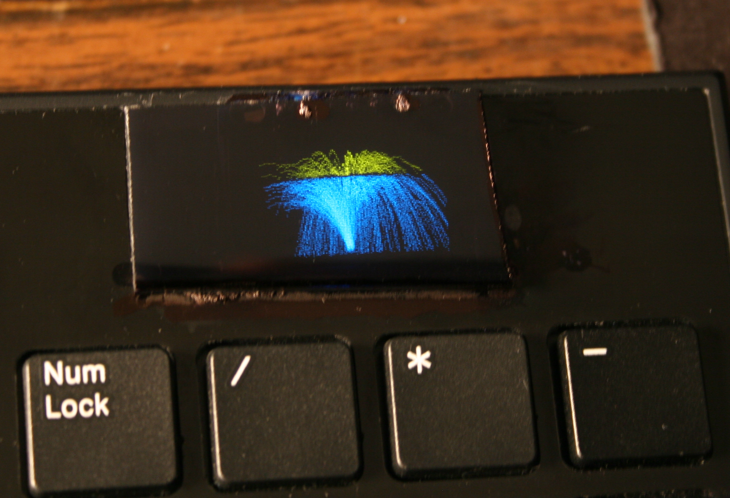
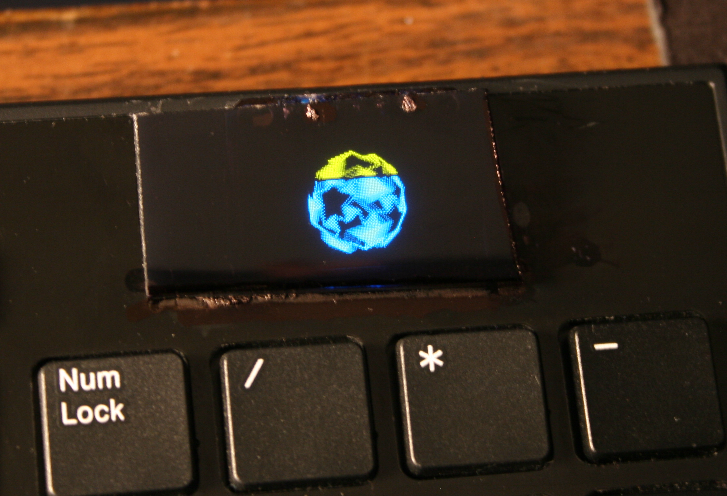
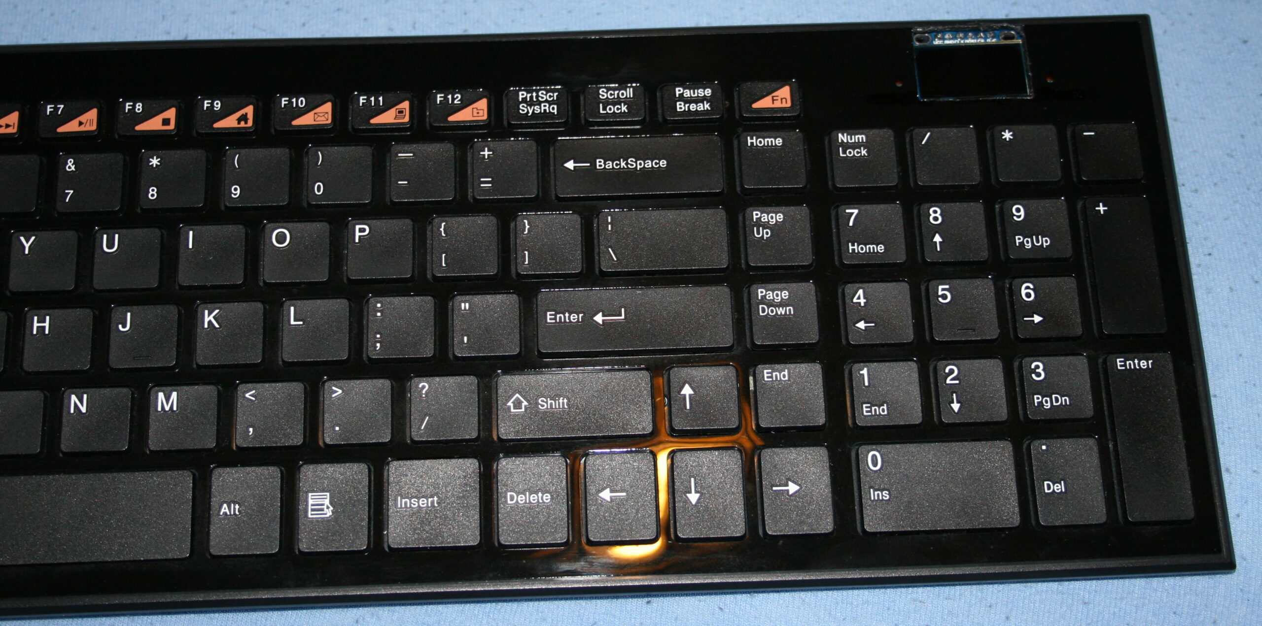
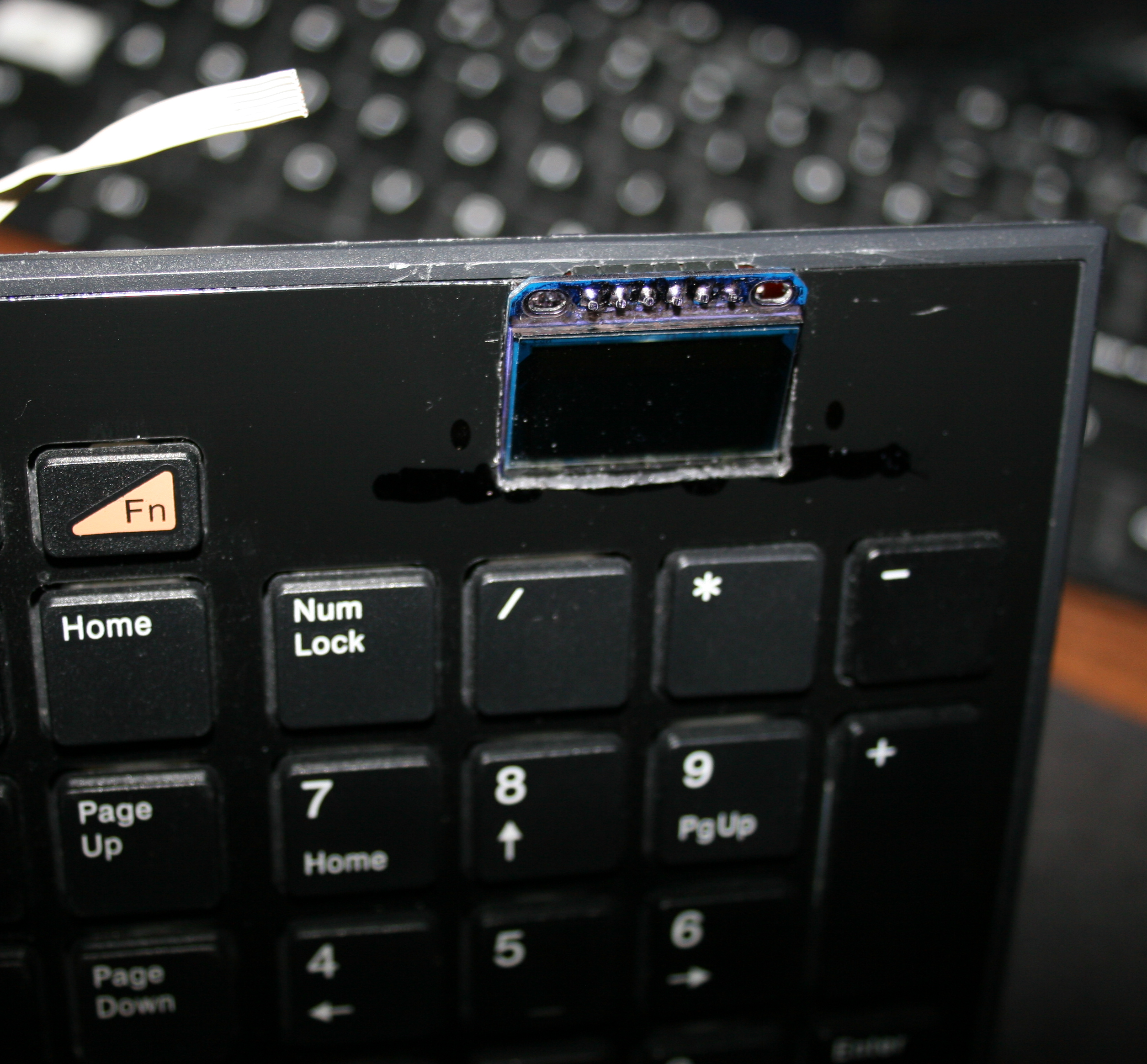
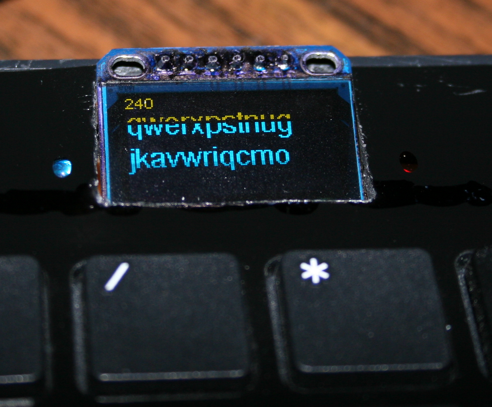
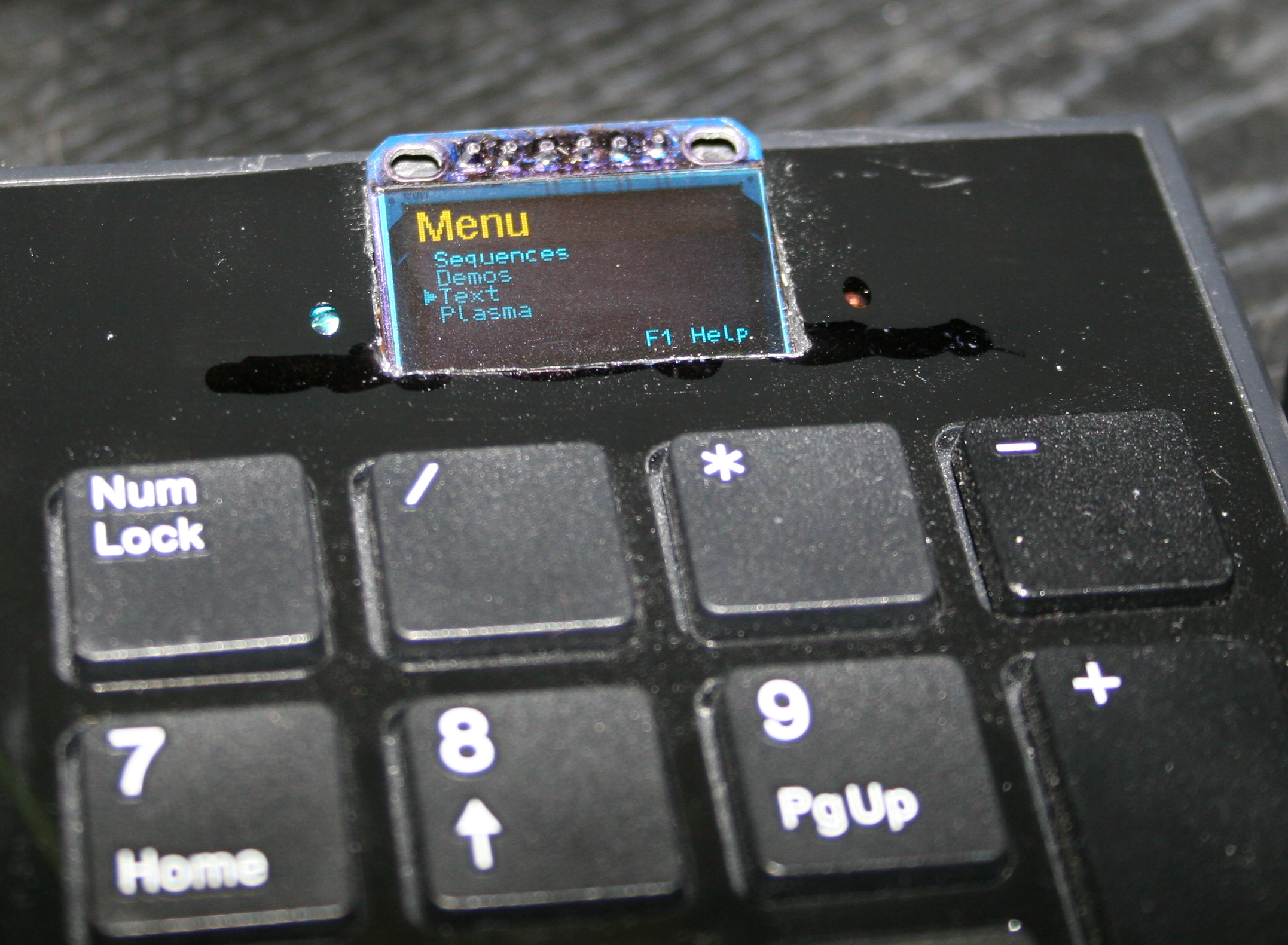
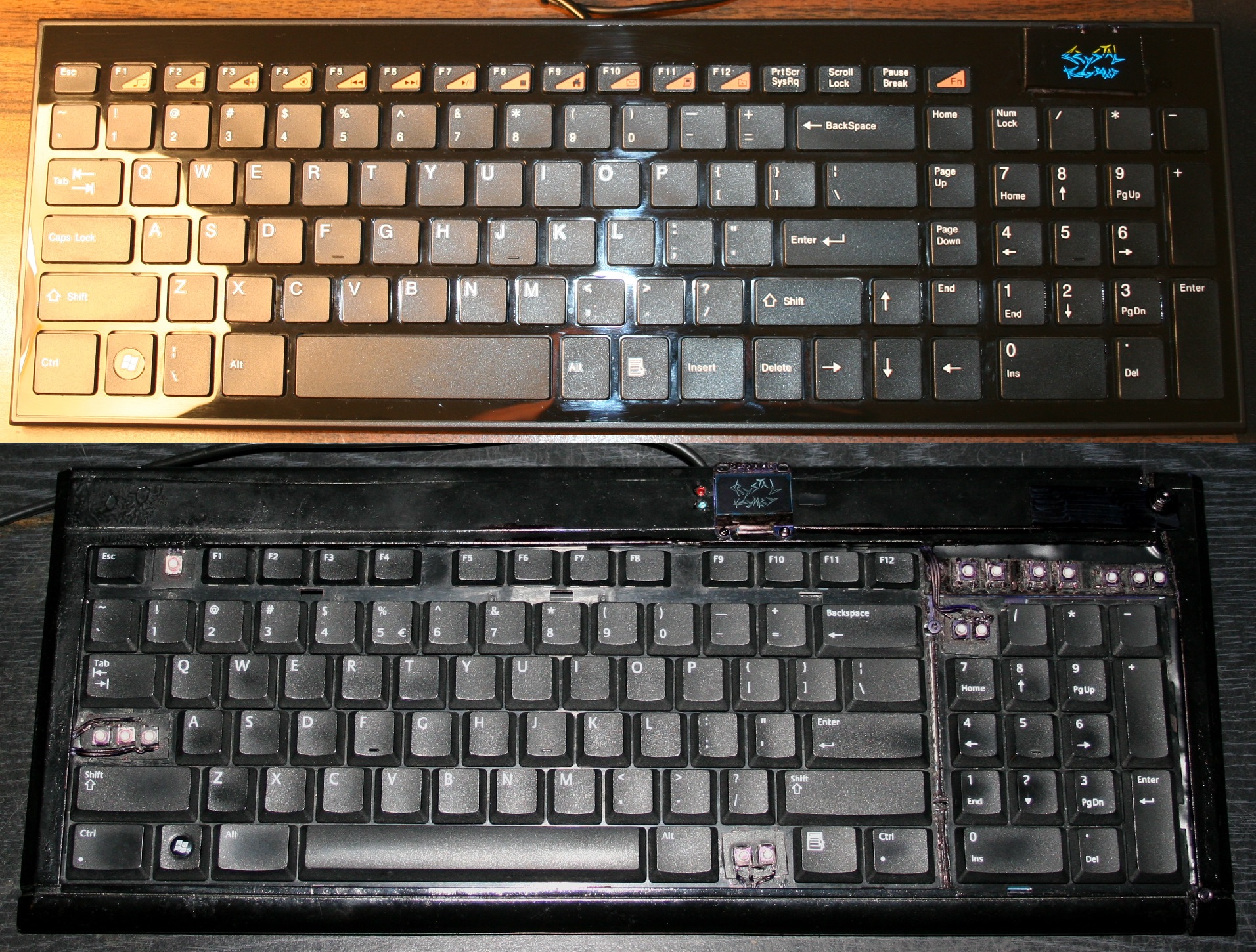
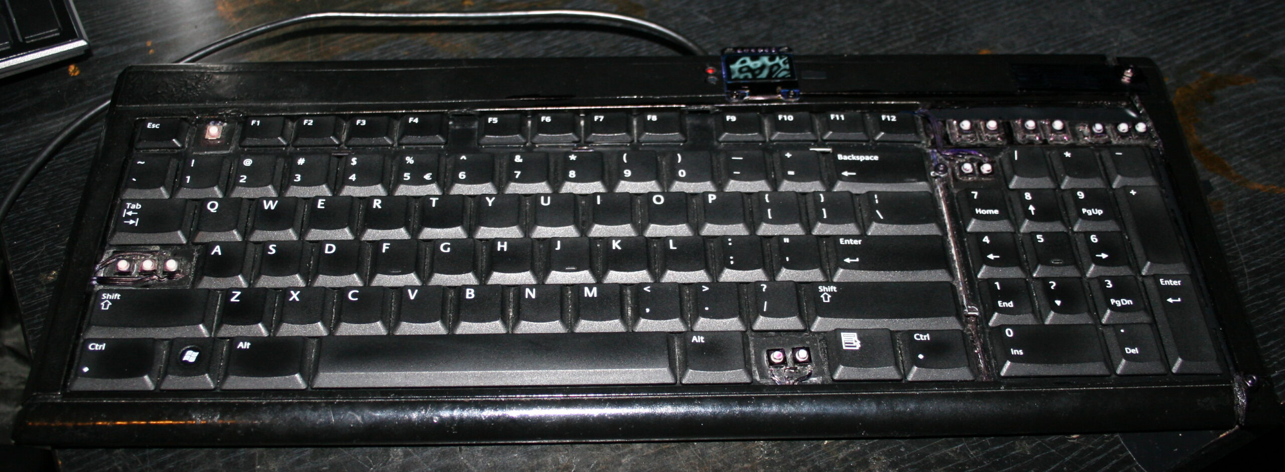
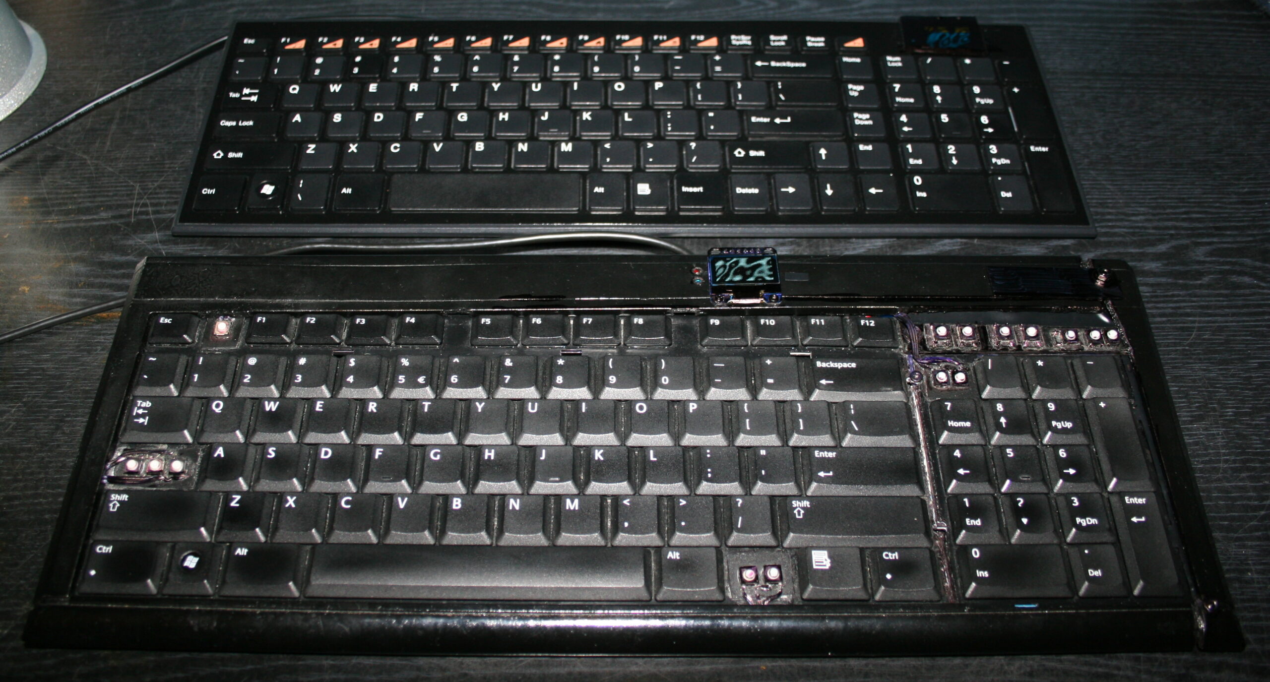
    The newer two of my heavily modified keyboards. This time having Teensy 3.1 (or 3.2) as microcontroller with a tiny 1″ monochrome OLED display. Firmware was based on Kiibohd, it was a fork with my extensions. I added display support (with a library), menu for editing e.g. macros/sequences, few demos and a game.
    I did improve them further in my newer firmware, with bigger display and later made my own in here.

    🛠️Modifications

    Light press

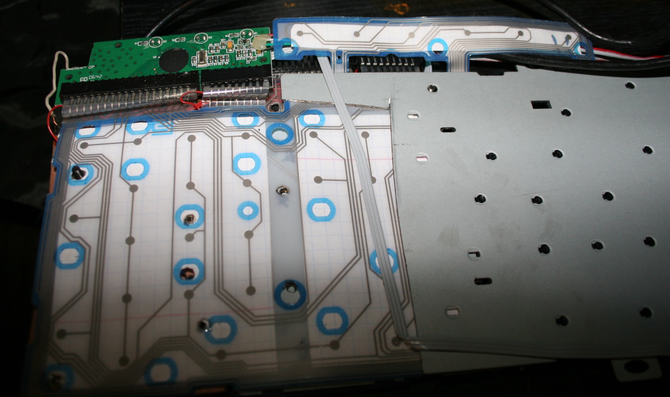
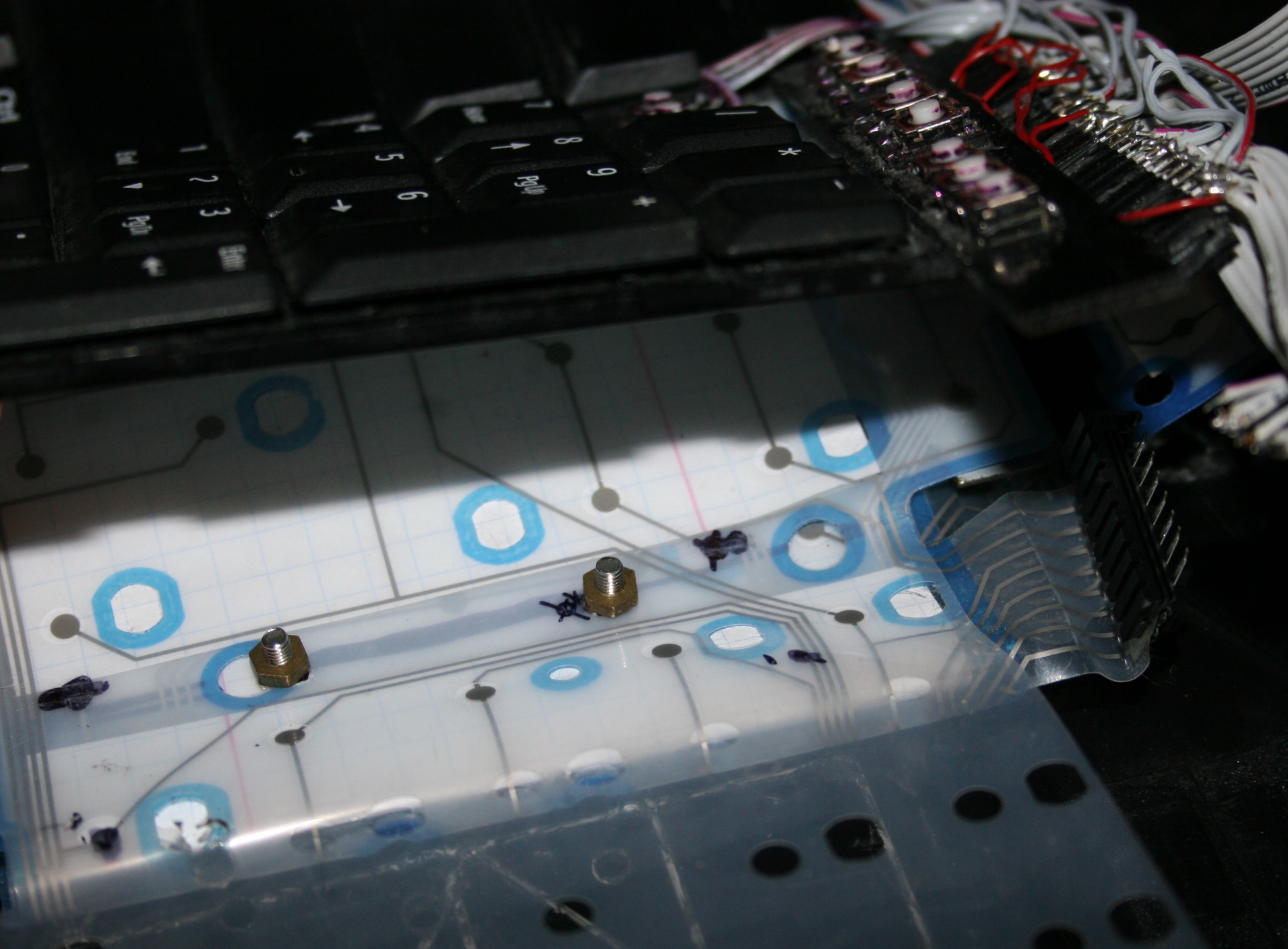
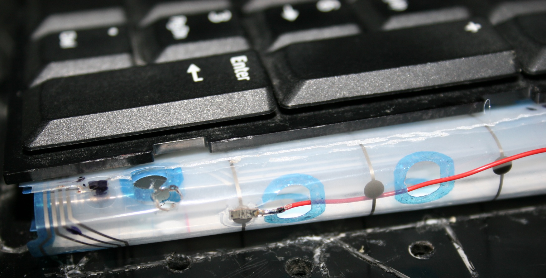
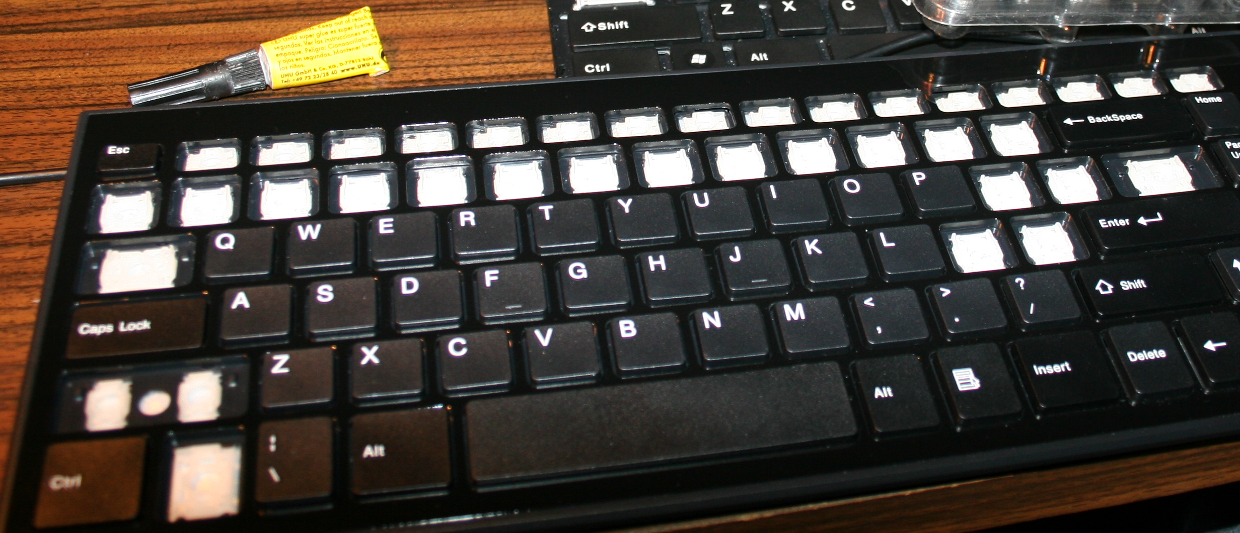
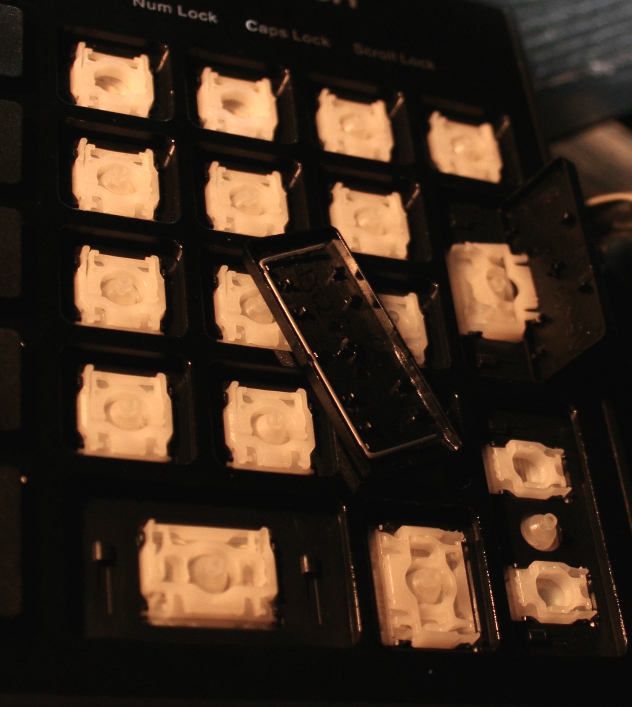
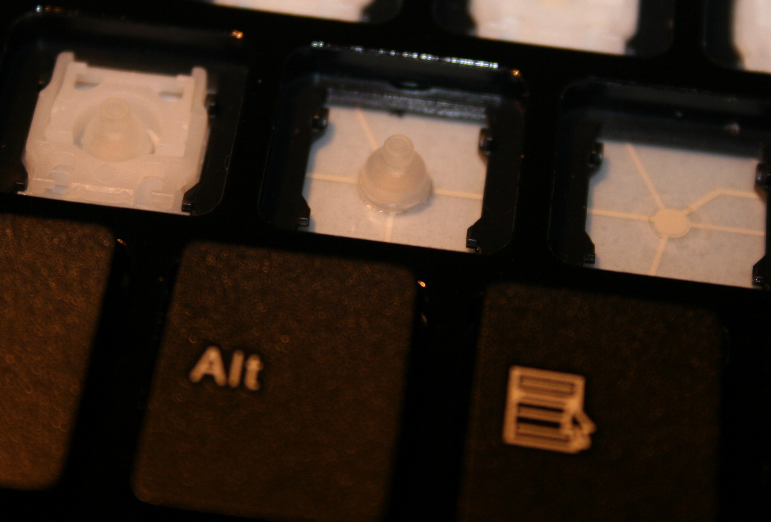
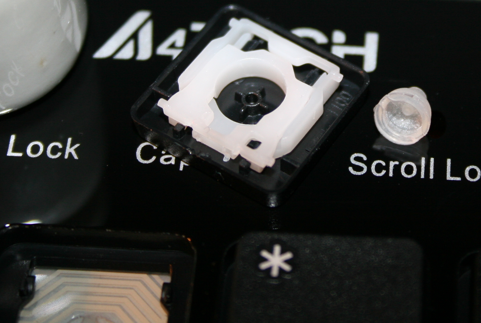
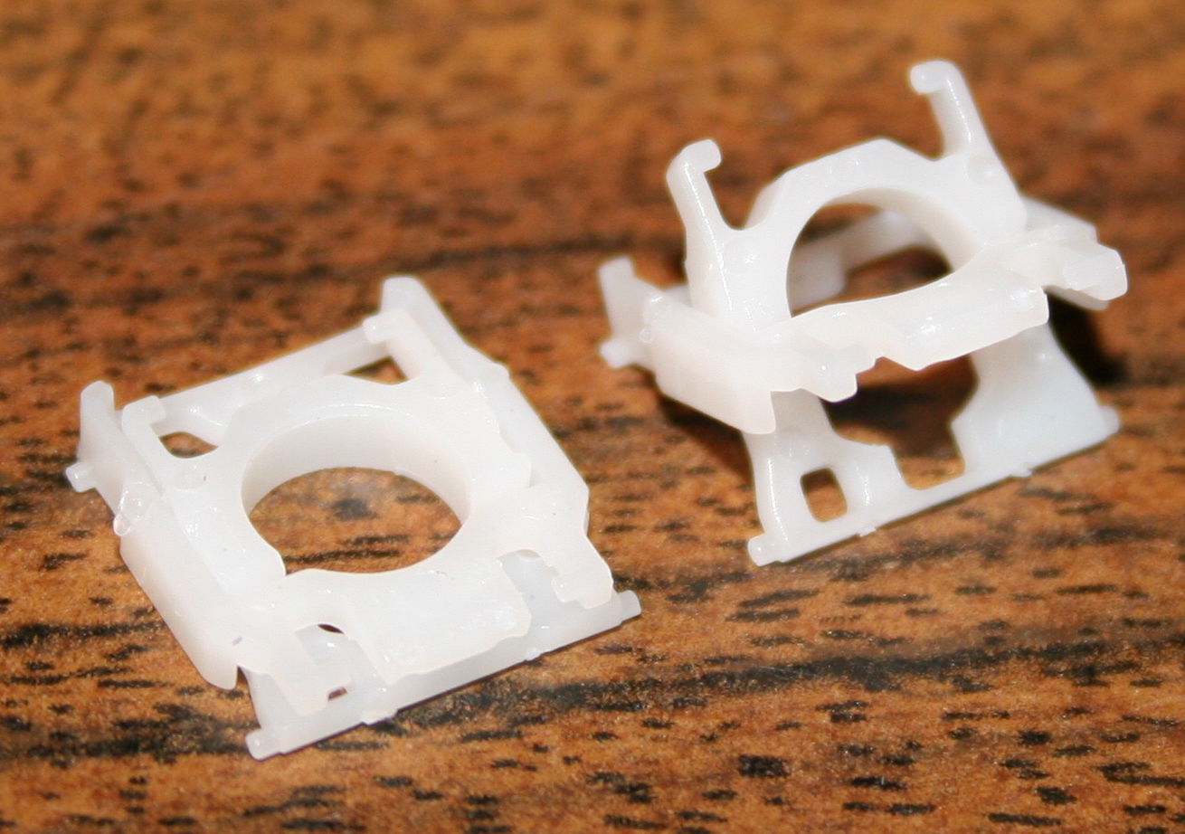
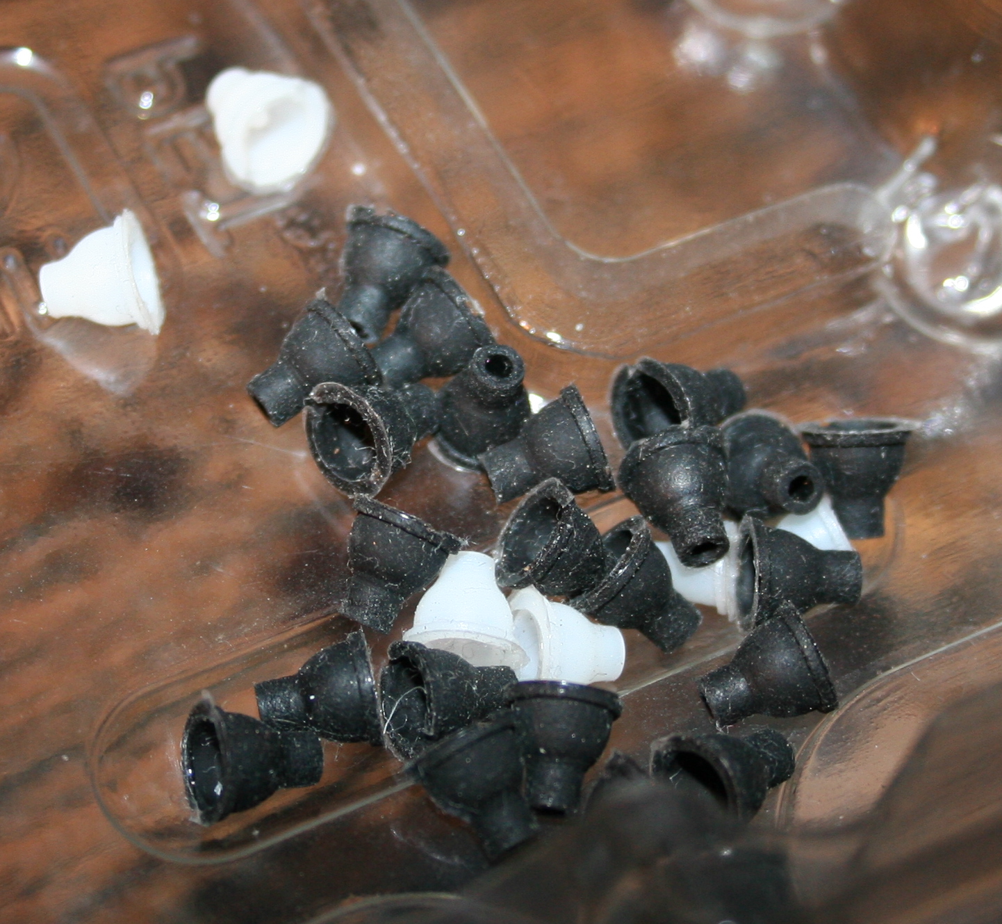
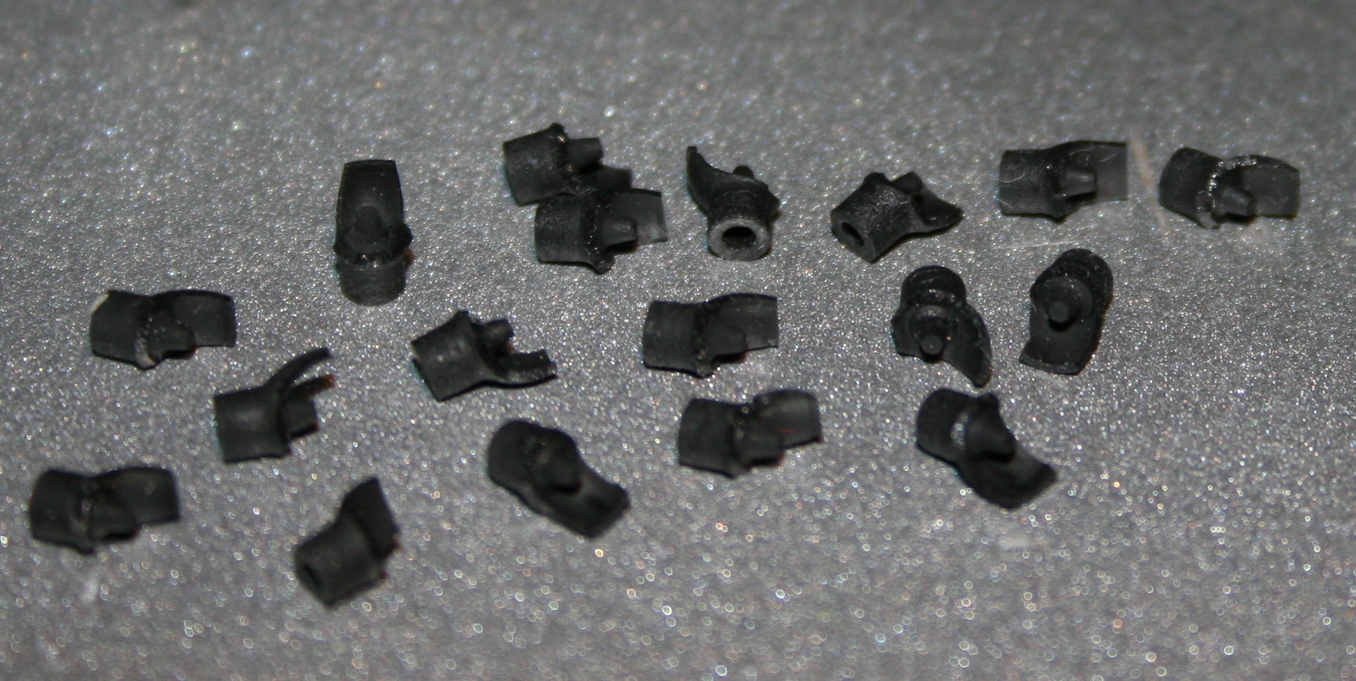
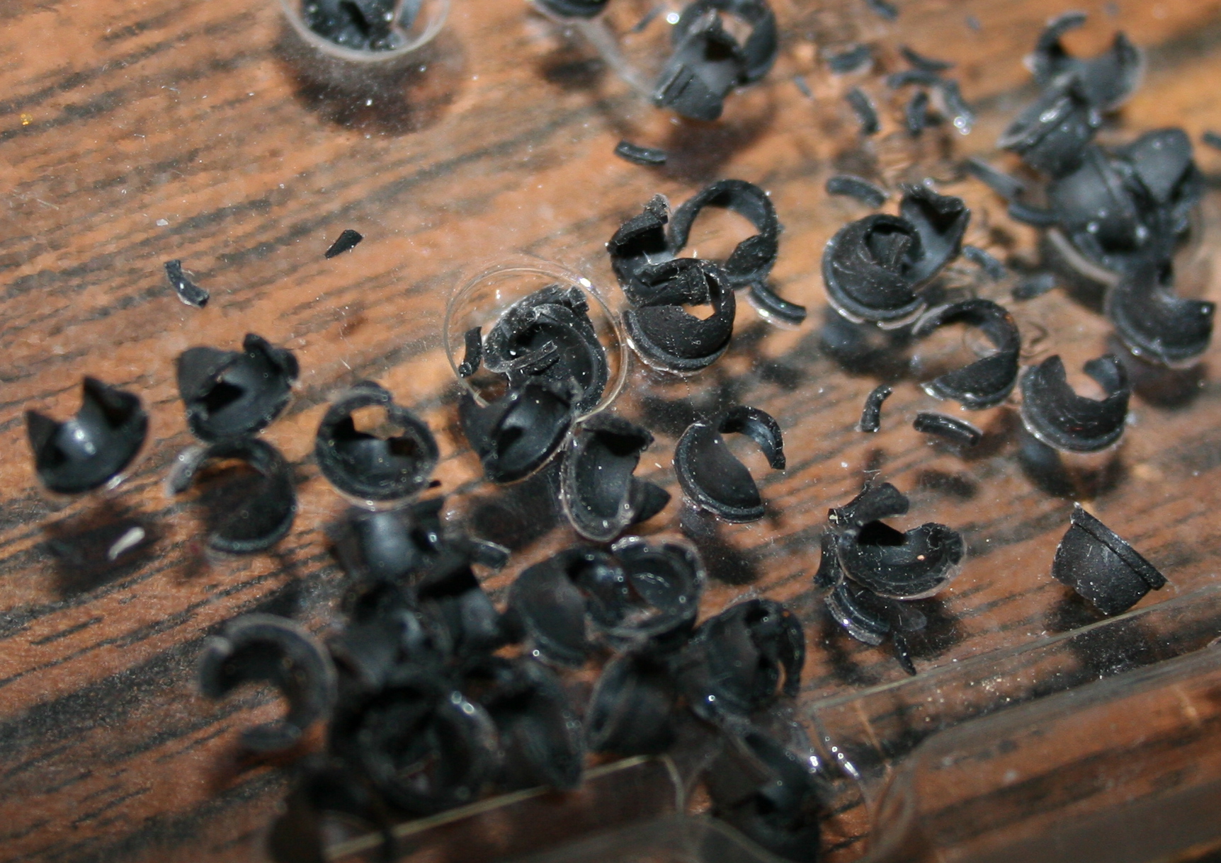
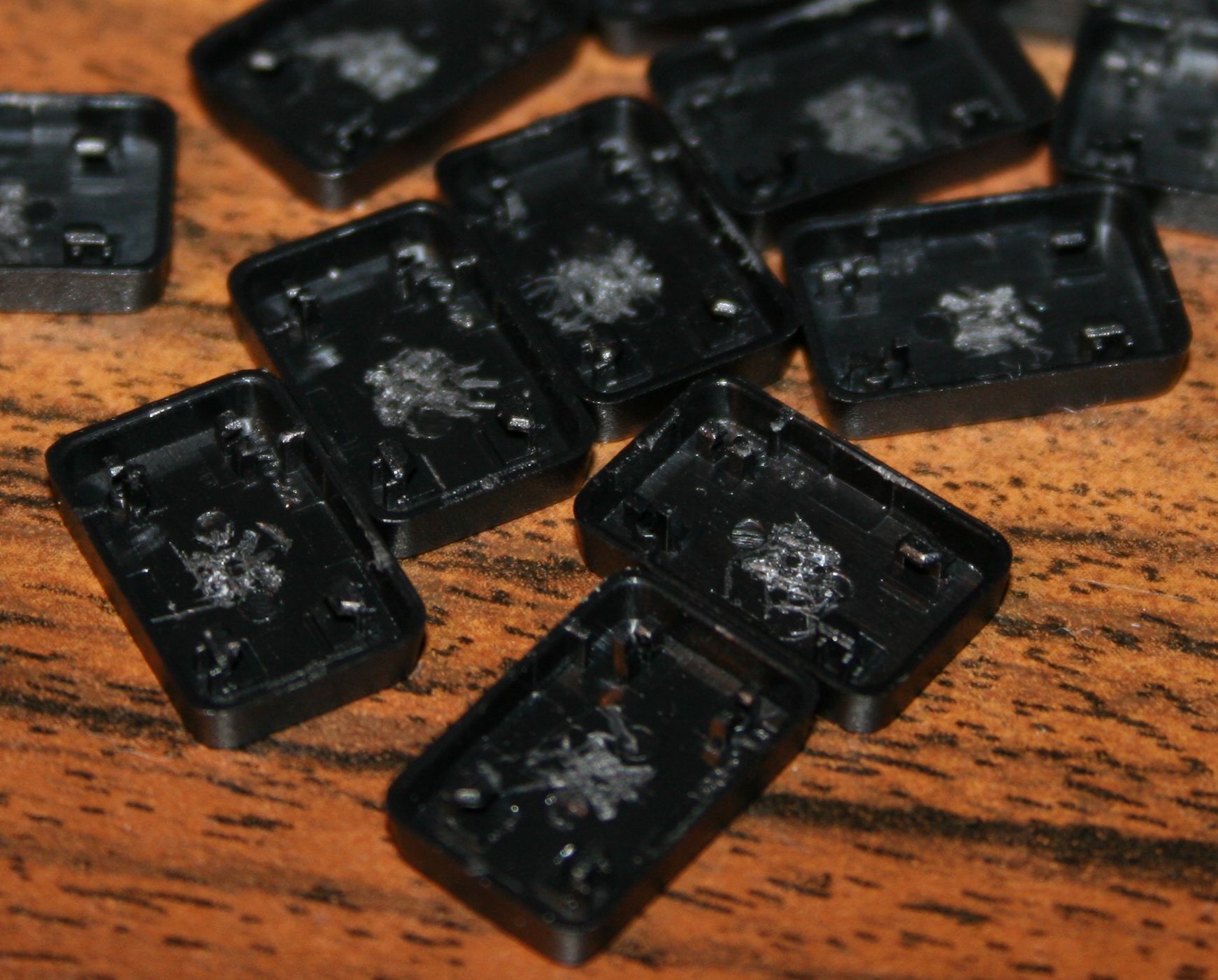
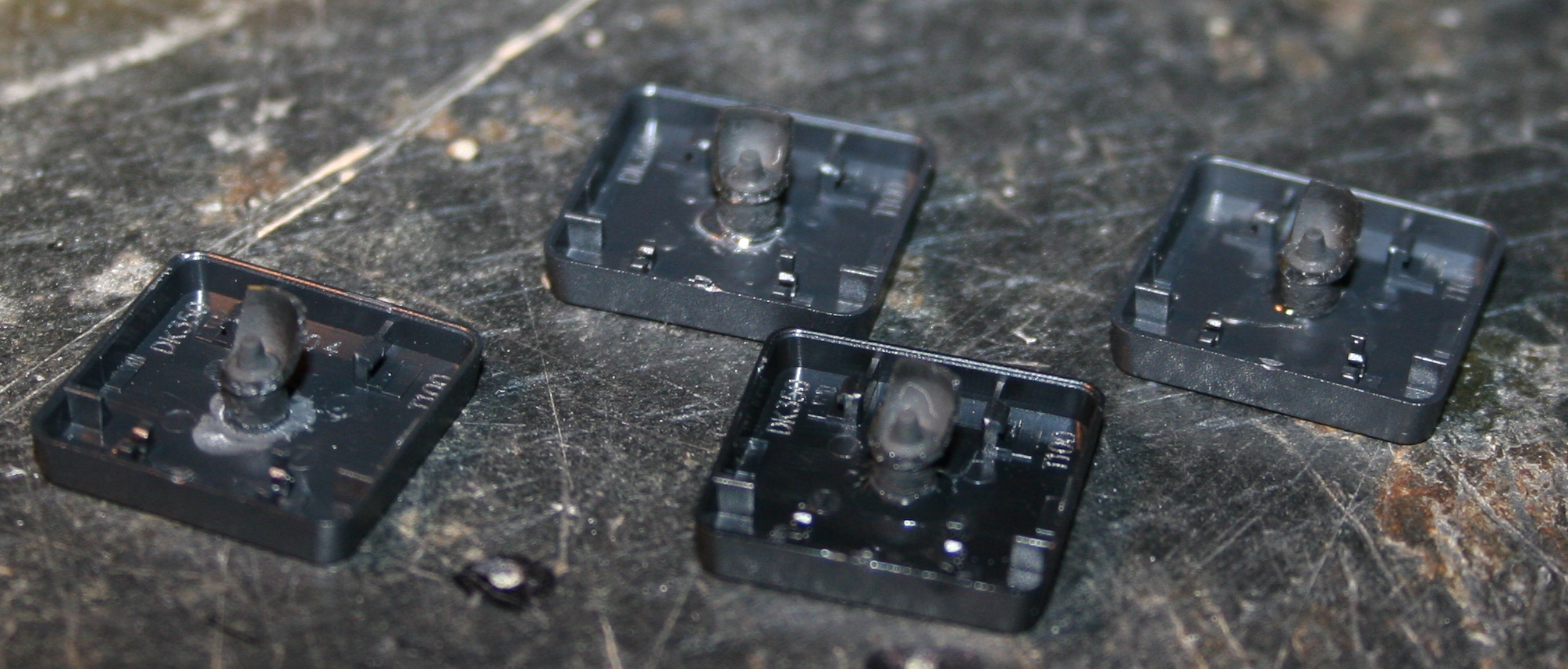
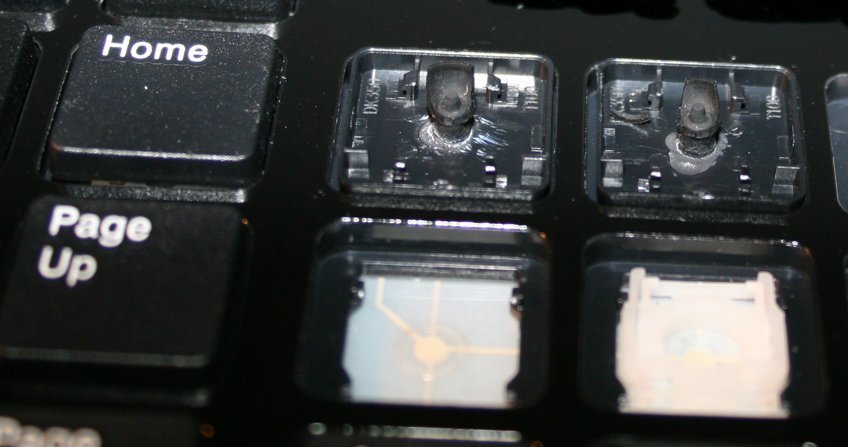
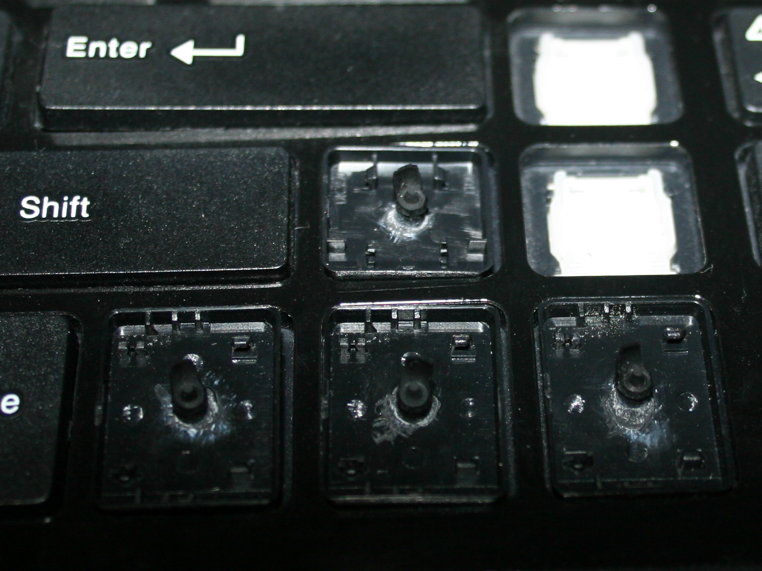
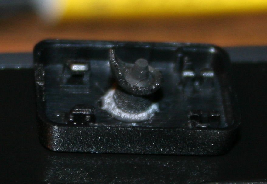
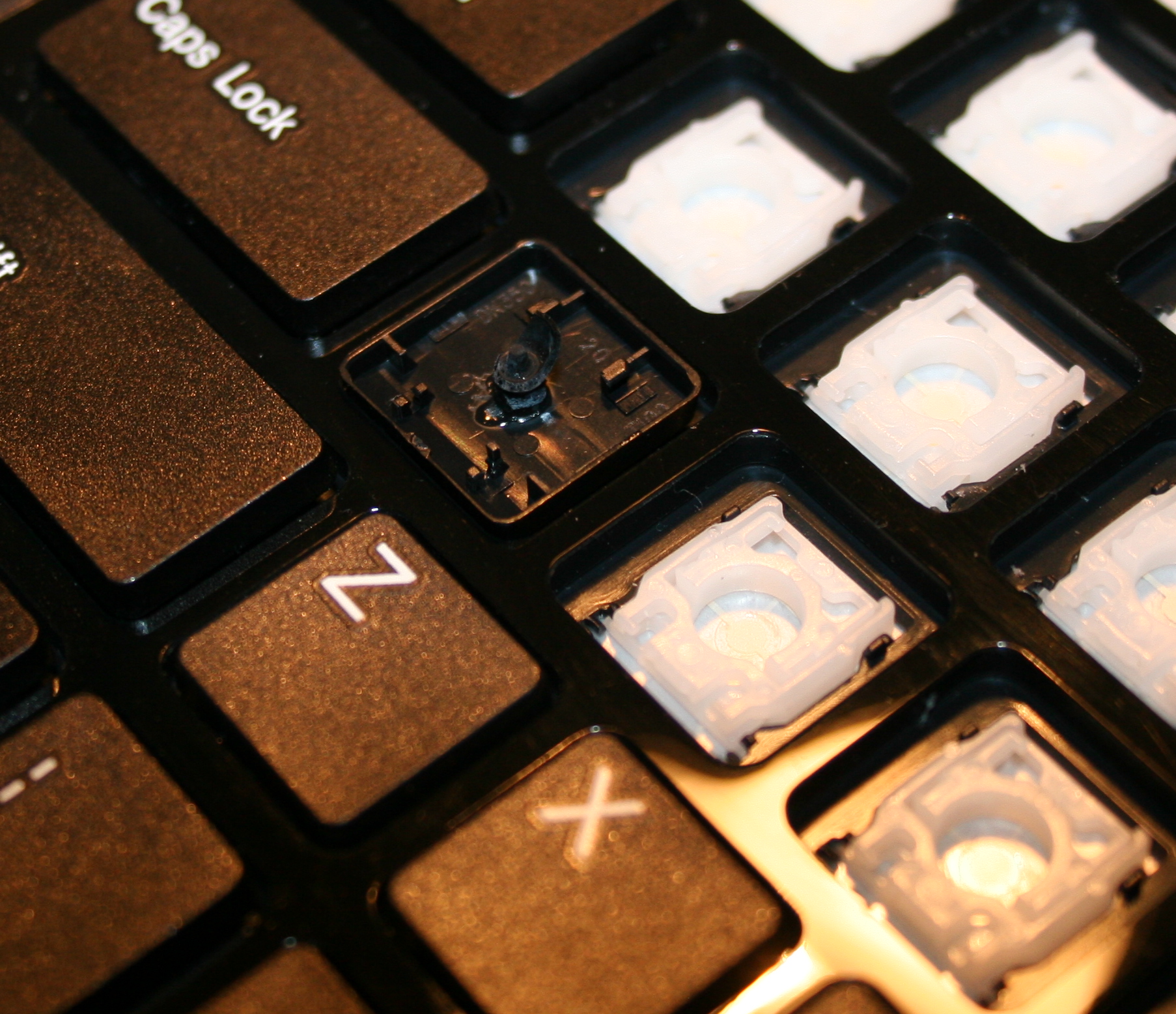
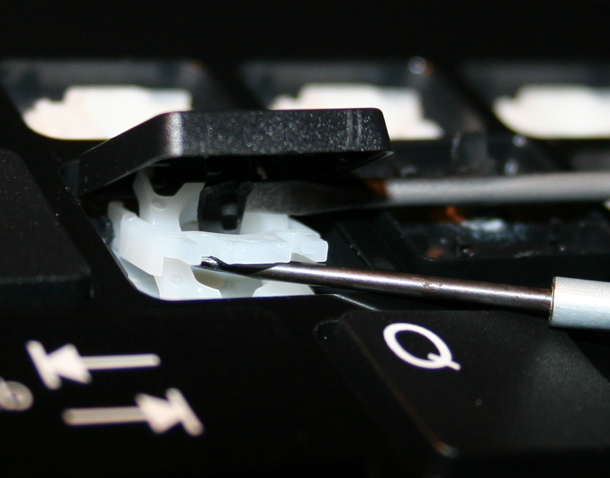
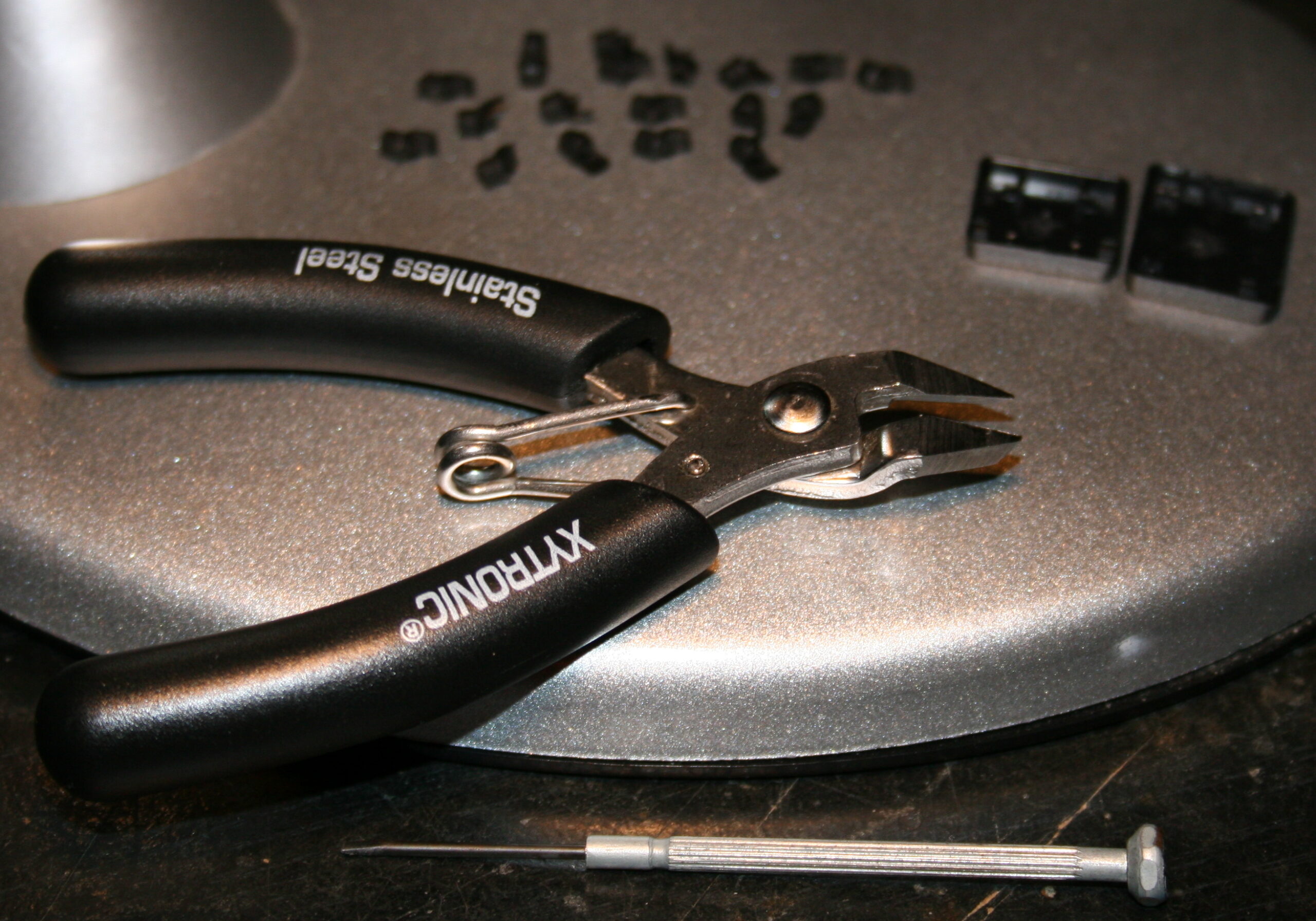
    Rubber domes reduction for minimized pressing (actuation) force and distance. Simply more pleasant and comfortable. Also healthier, since the risk of keyboard injuries decreases. I do it always for all my keyboards. Process with info shown here and in gallery below at end.

    ⌨️Additional keys

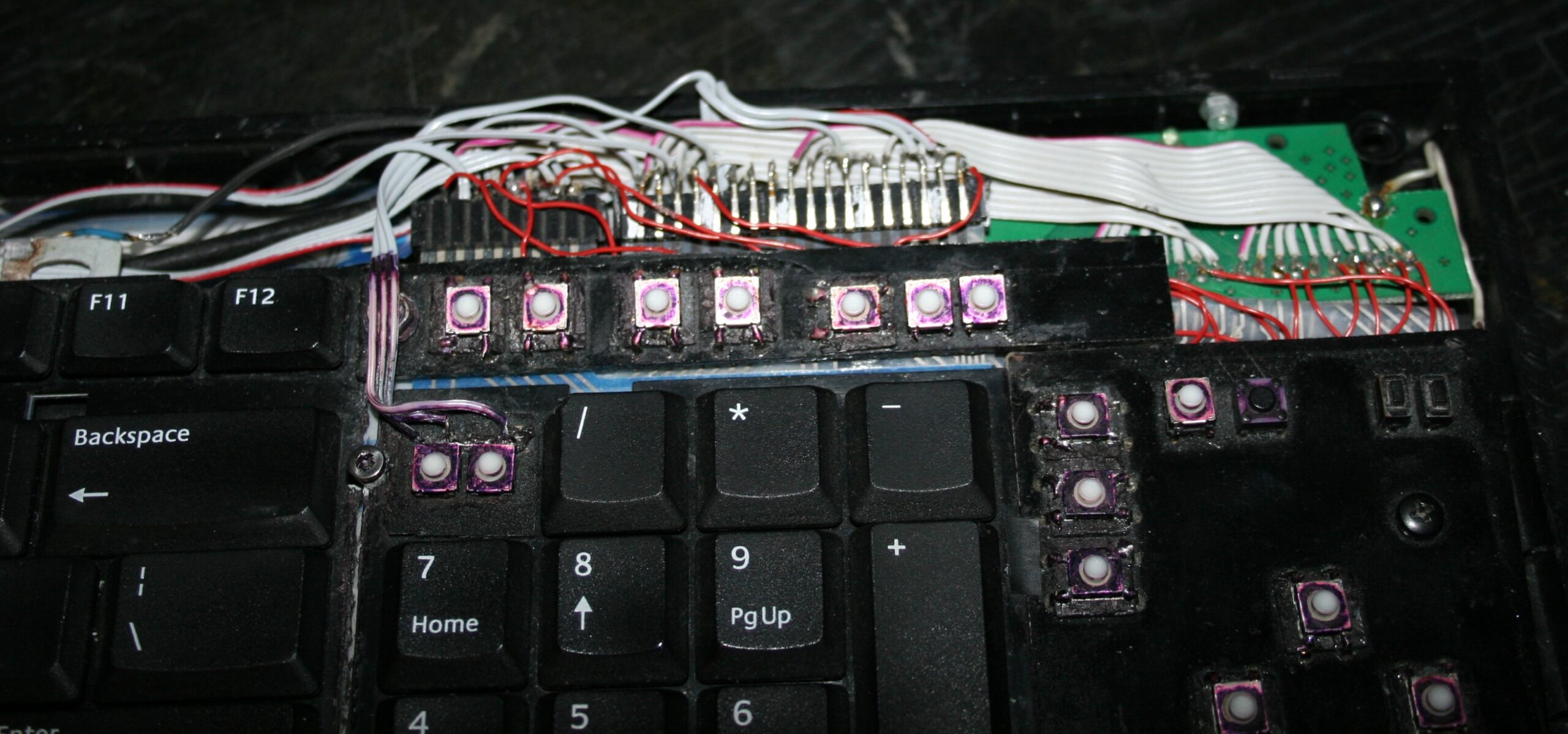
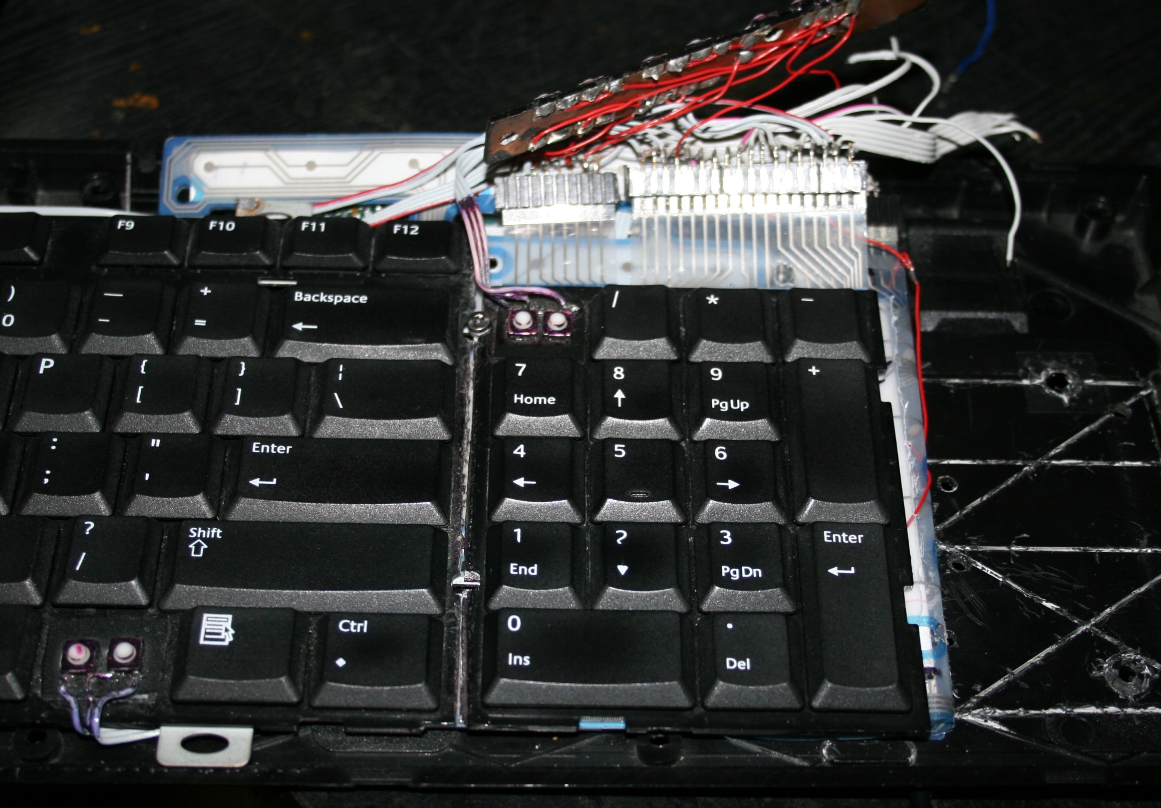
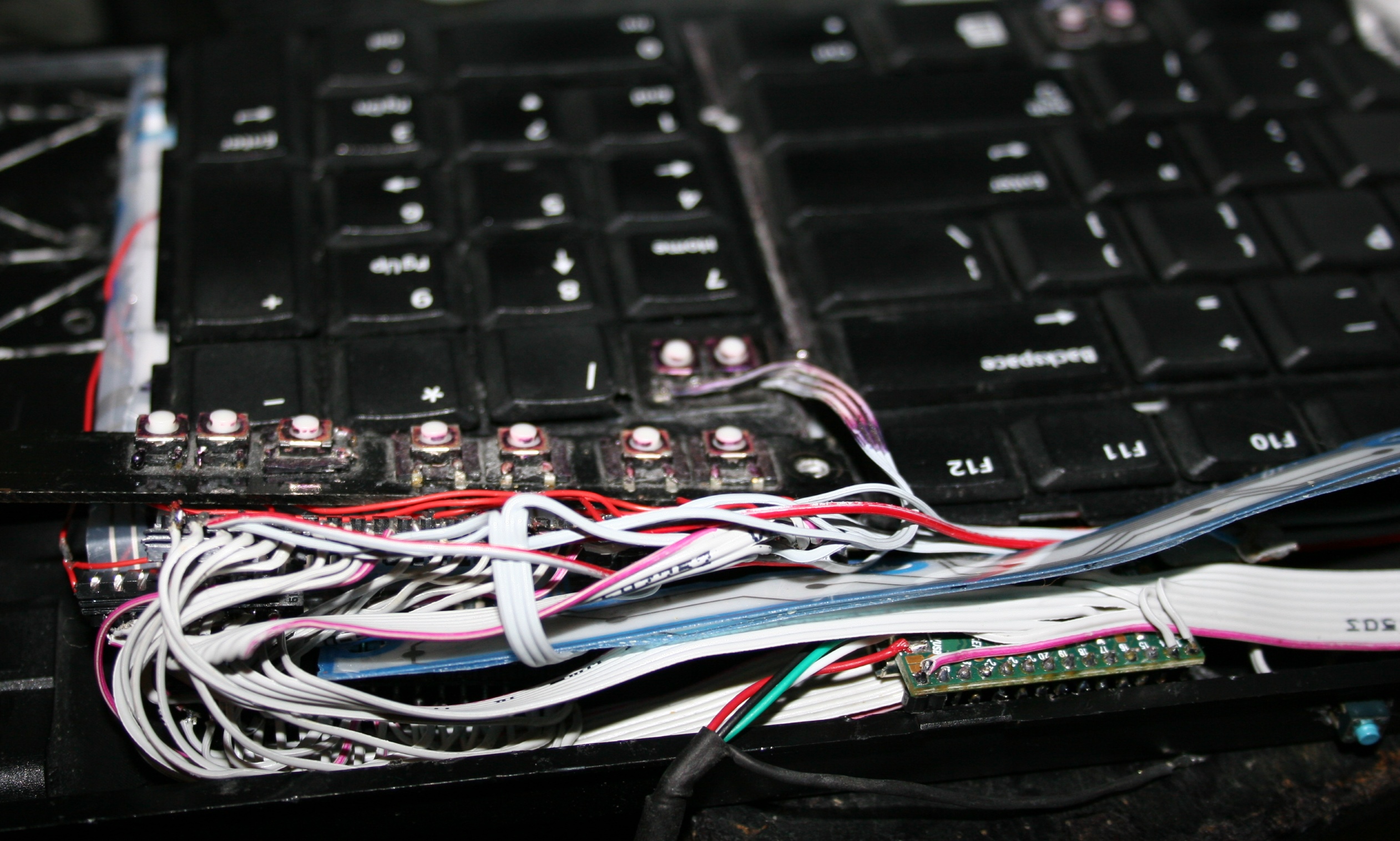
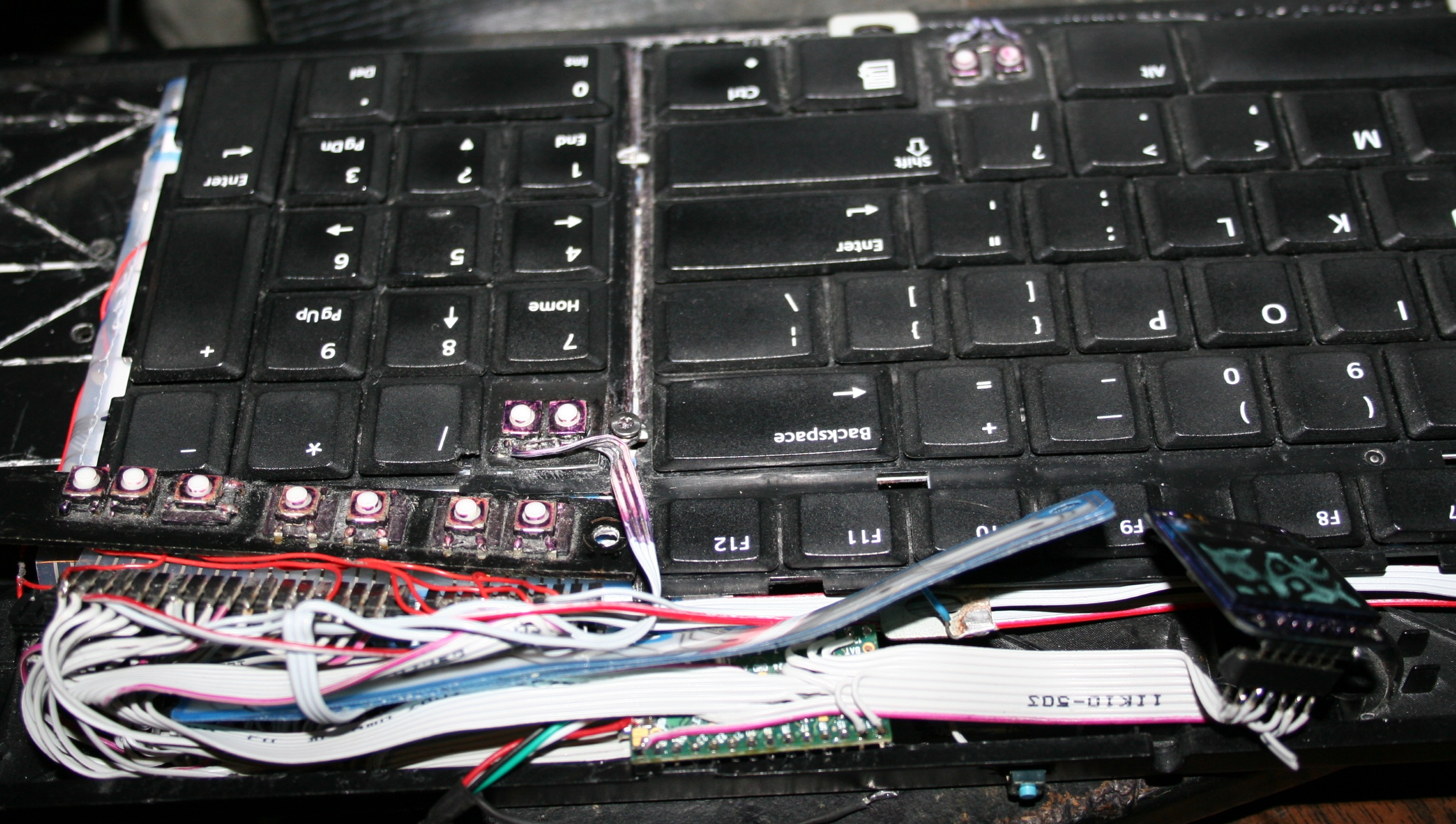
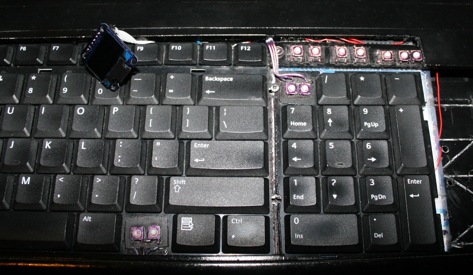
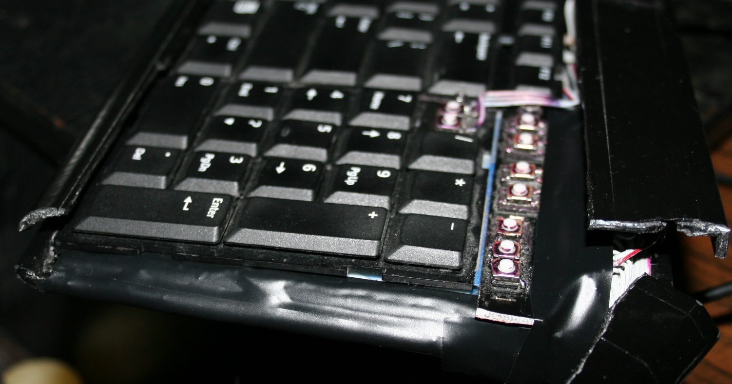
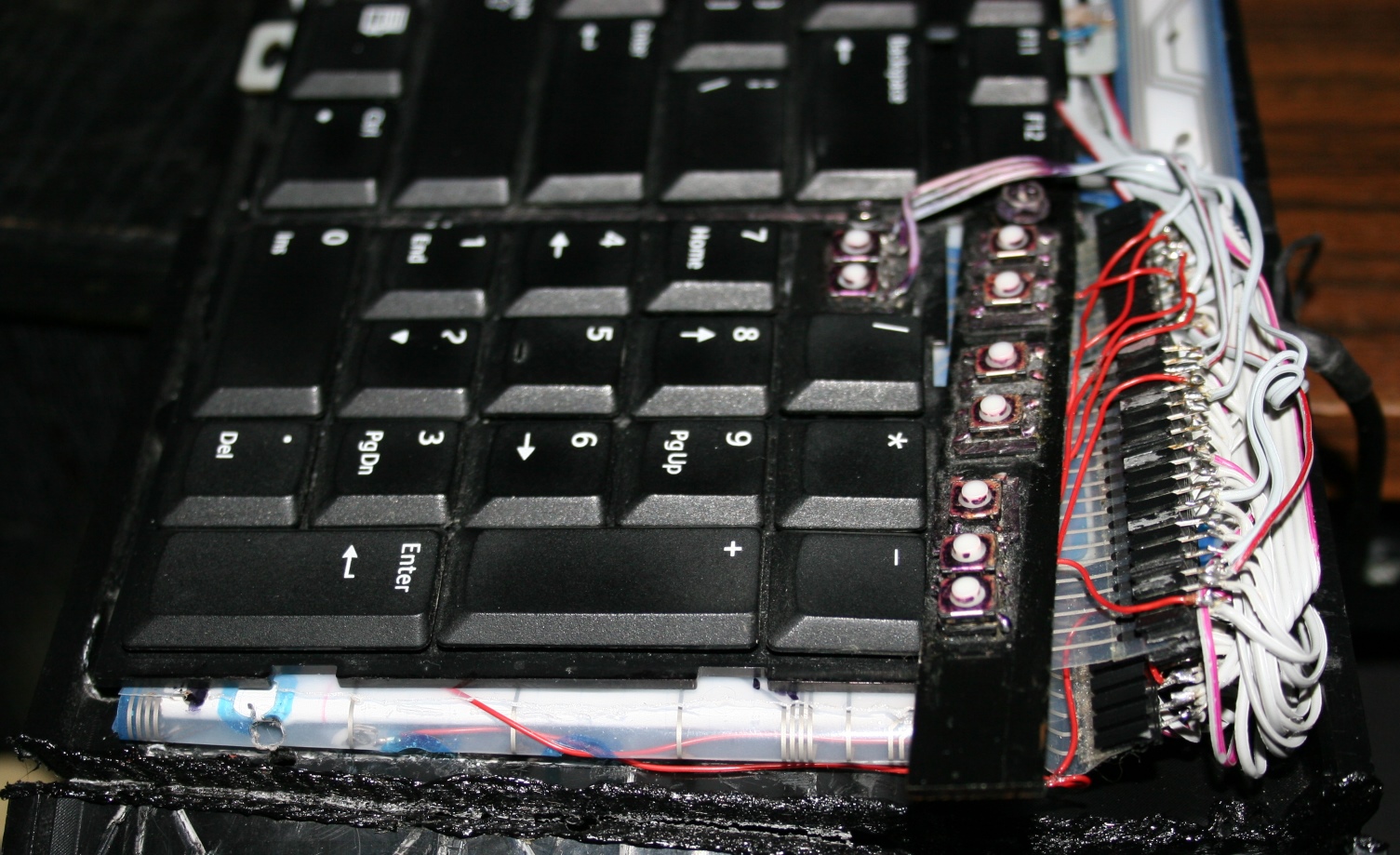
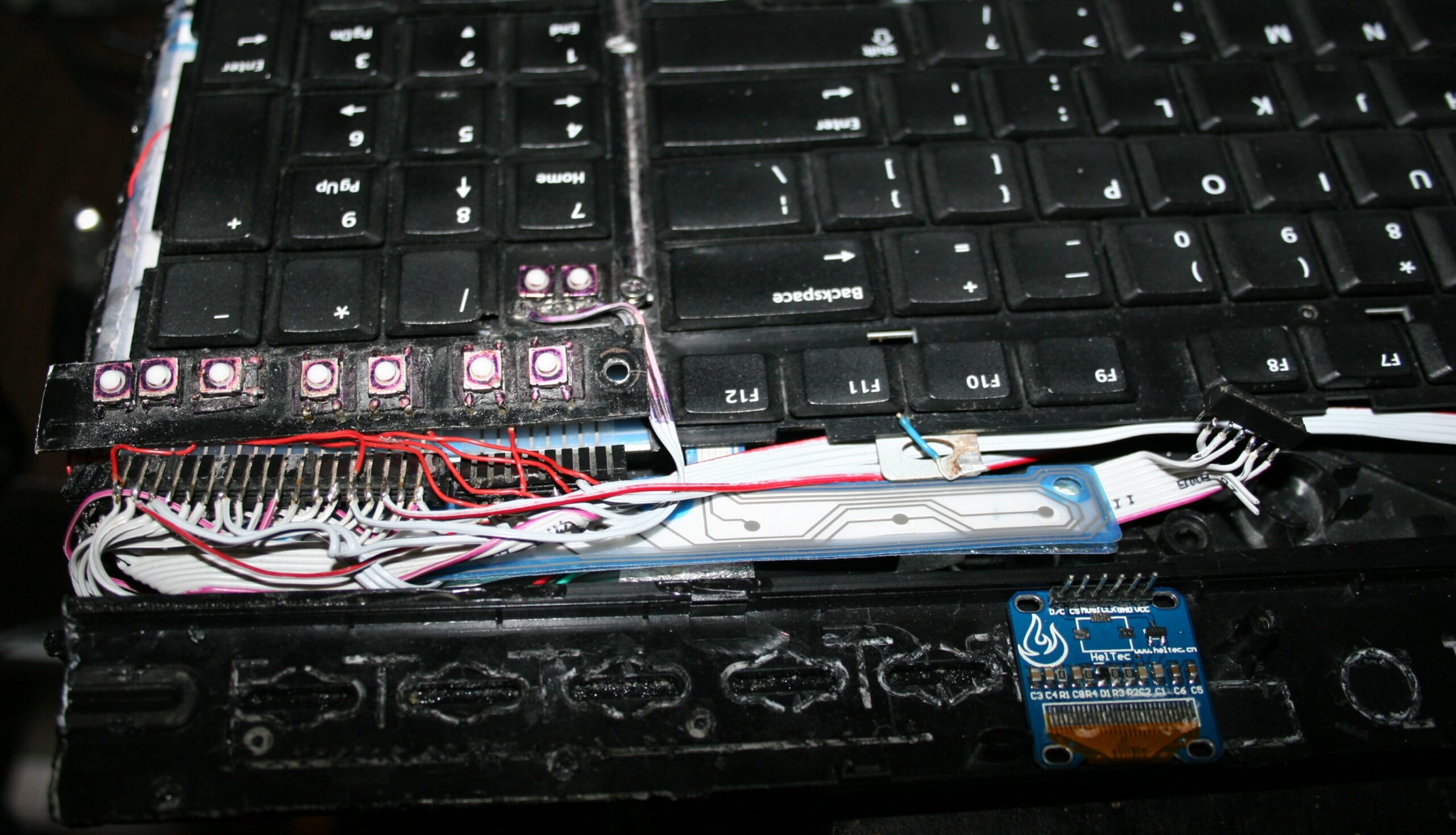
    For CK4 there are also few small extra keys. Which were present already in my earliest keyboards CK1 and CK2. Those are glued on top and are made from lightest 0,5N switches available. The row above numpad is used for my audio player control. Rest is custom. This part is optional and I didn’t do it for CK3. The disadvantage is the difference in pressing those switches and much lighter normal keyboard keys. They are smaller so you can fit more, but are less convenient to press. Lastly, regular keys can be used to switch layers instead.

    ⚙️Microcontroller (MCU)

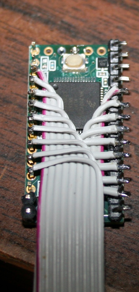
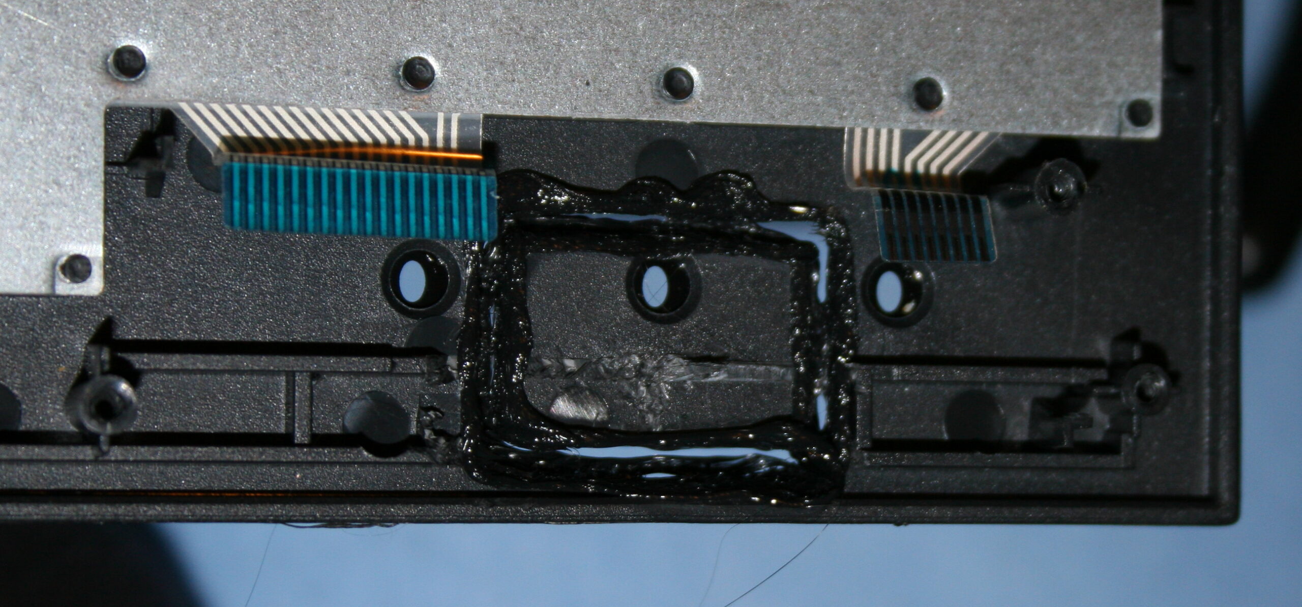
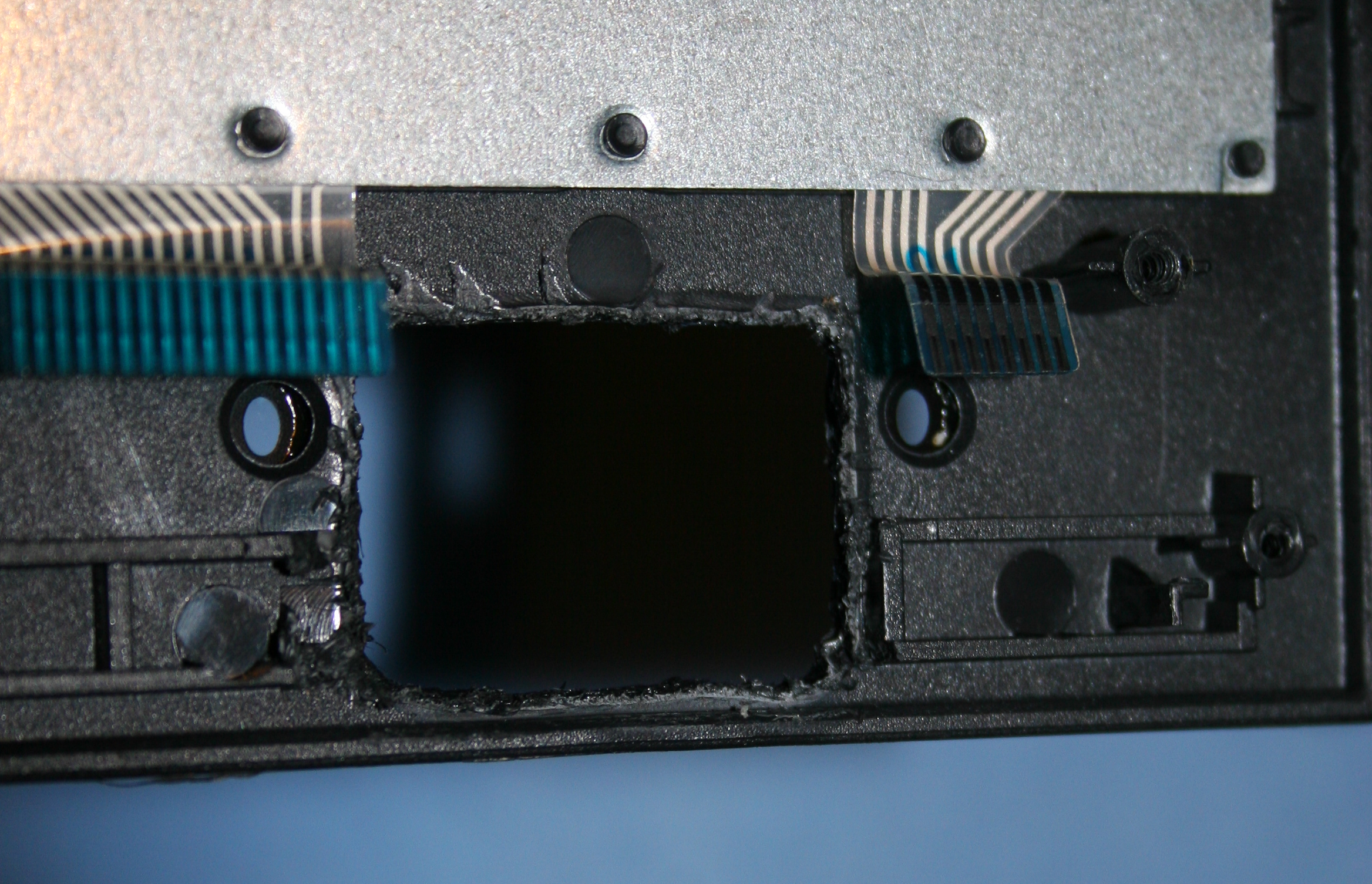
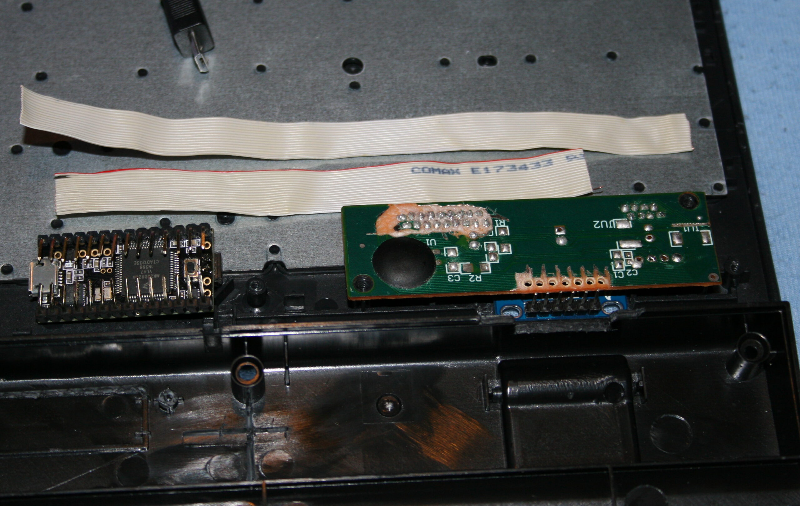
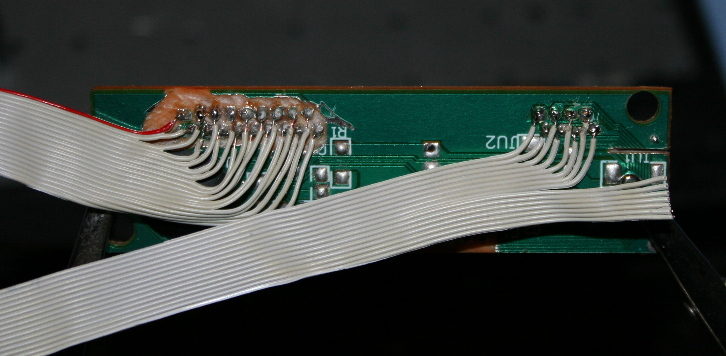
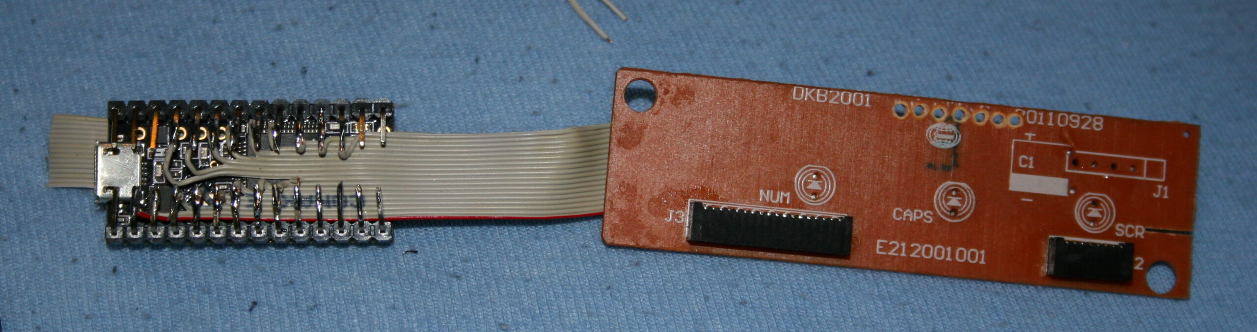
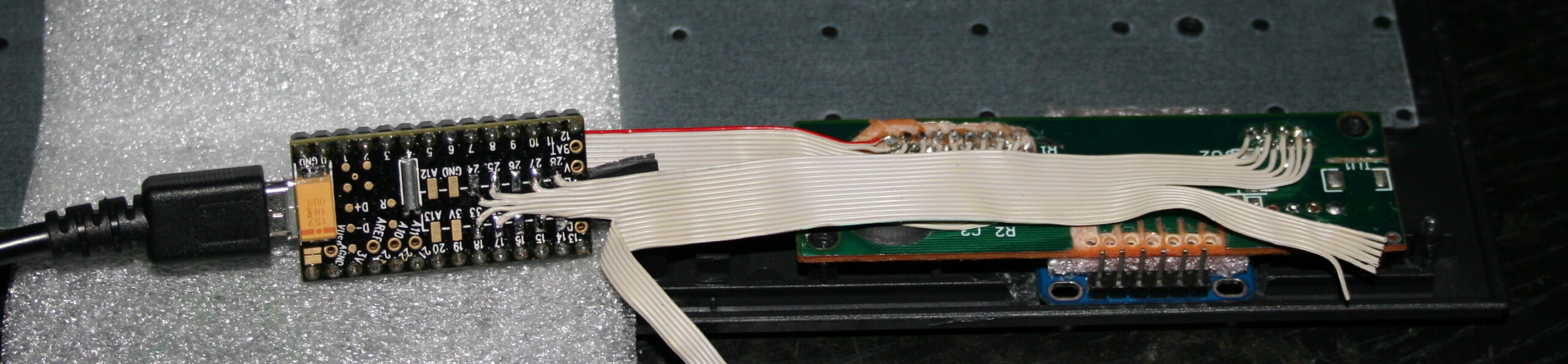
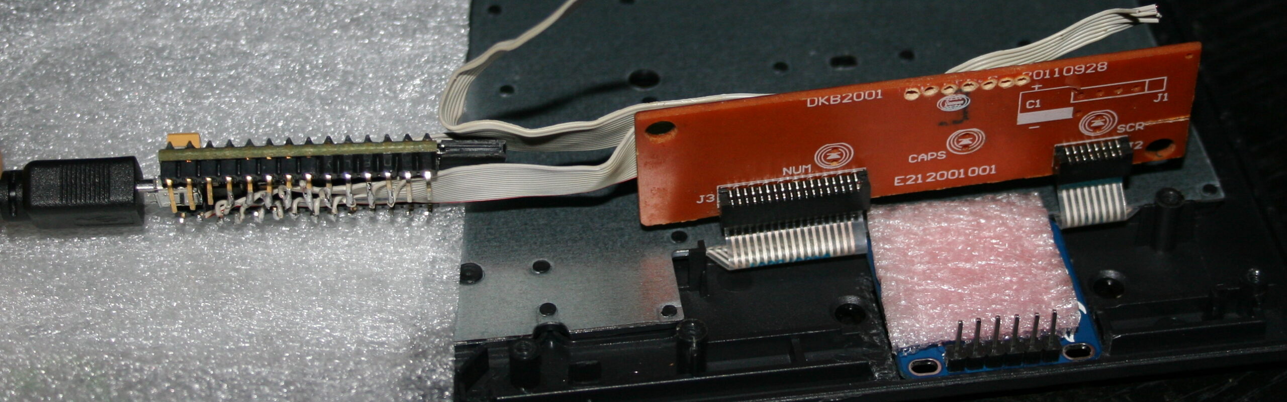
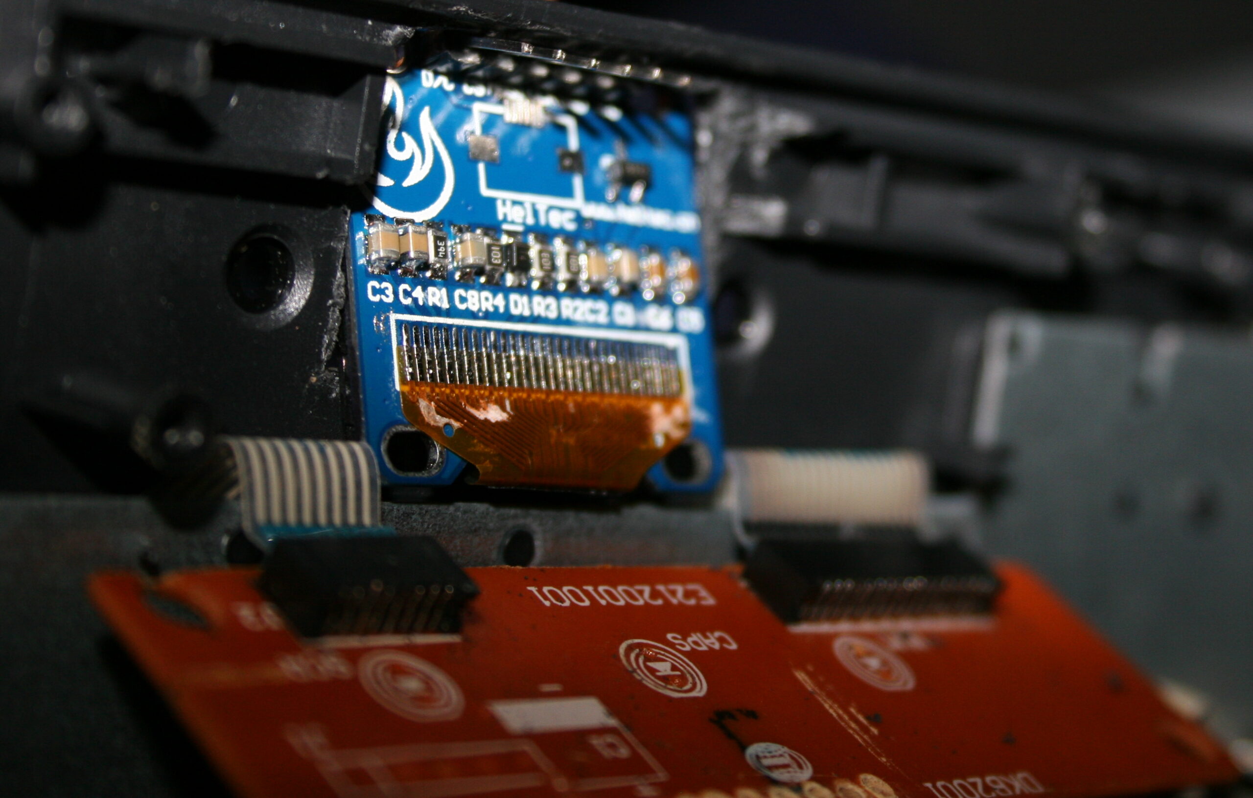
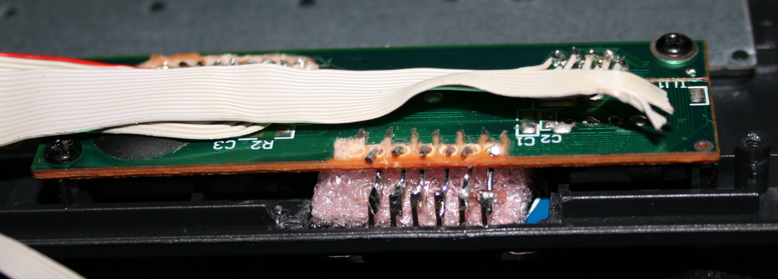
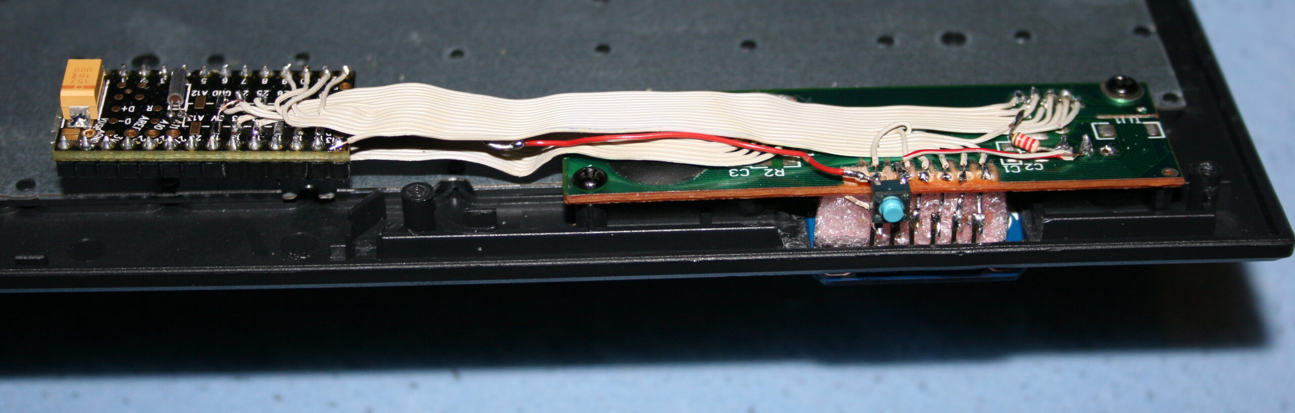
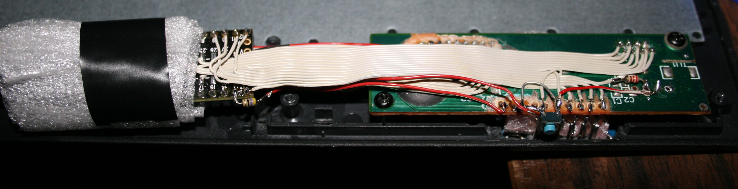
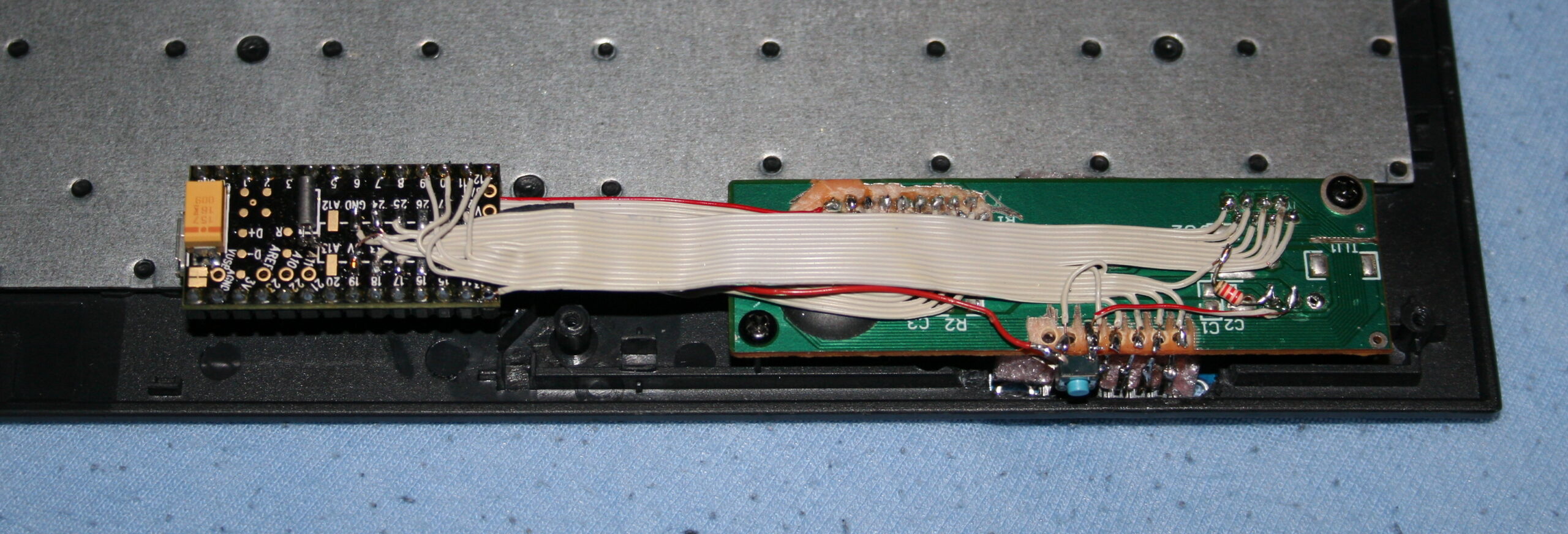
    The second step was replacing the keyboard controller board, with my own. The hardware is composed of Teensy 3.1 (or 3.2) with a tiny 1 inch OLED display (SSD1306, monochrome, 128×64) and a bunch of wires to connect to the original keyboard’s matrix.

    The reason for this was to take advantage of already made open source Kiibohd controller allowing any imaginable keys assigned and layers. Also possible are macros, key combinations and even mouse buttons and movement simulation.
    But changing any of this required rebuilding controller software and uploading to controller, through already present USB. Which is a major flaw for me.

    📊Features

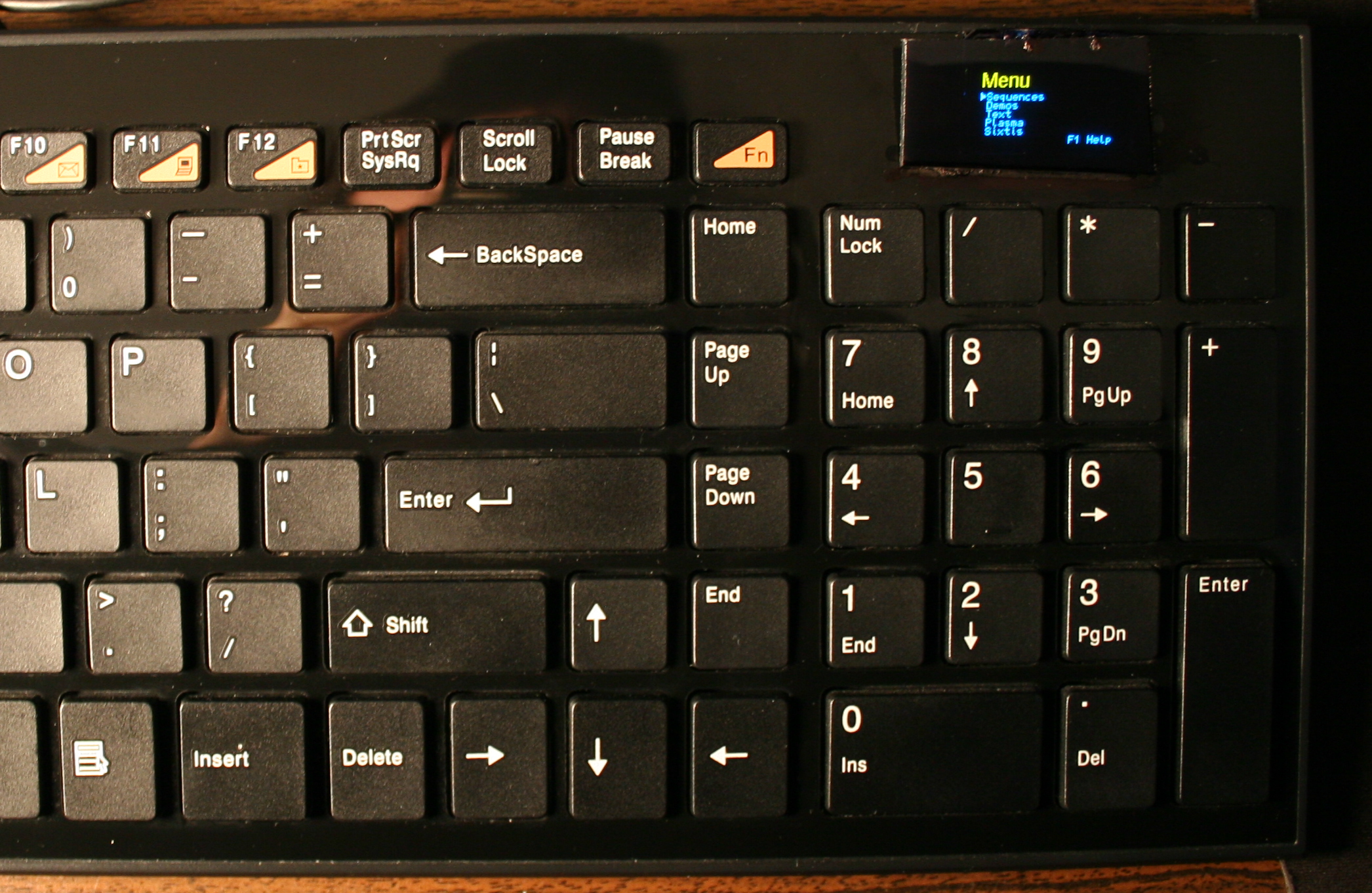
    After getting it to work, I implemented my own menu where you can edit sequences, stored in memory (remembered after power off). The sequences are very useful for not typing passwords or simply binding some useful macro combinations or commands dynamically. Which needed a display and menu for entering.

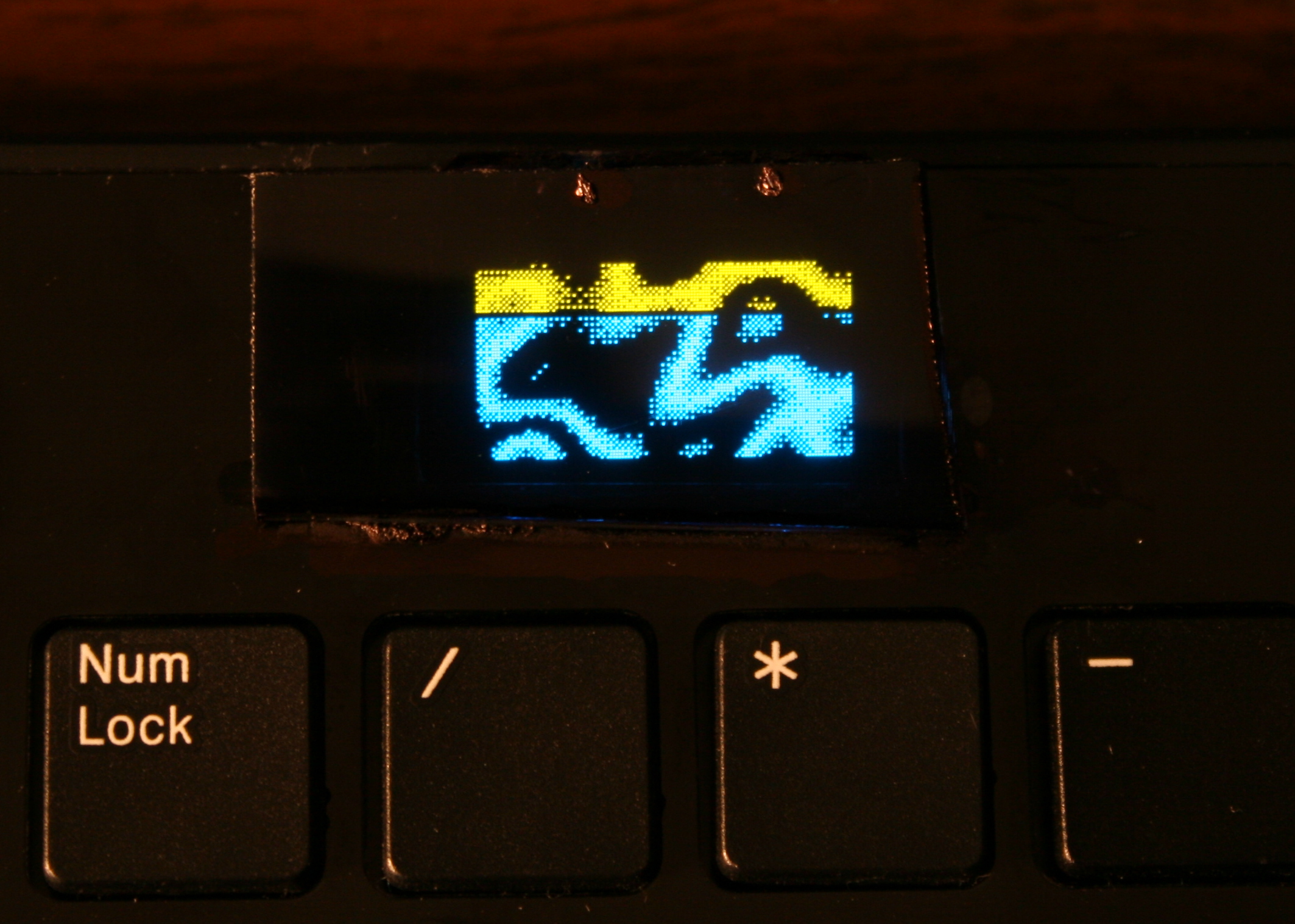
    Once I’ve done the useful stuff, I got carried away and implemented several demos on display and even a falling blocks game.
    I also wrote about it in this forum post.

    📂Sources

    The code is in my fork here with some more detail. IIRC it can’t build anymore.

    ⌛Conclusions

    It was a bit simpler to start at the time, instead of writing completely my own later on bigger display. Since the display was so tiny I didn’t yet think of drawing all keys on it. And making them rebindable on display, instead of following the way all other FOSS controllers I knew did, that requires rebuild and upload which is way slower.

    ✅Summary

    For reference, here is a table with current status of all my keyboards, since start until present day:

    NameAssembly yearOriginal keyboardKeys actuation
    [gram force]
    Notes
    MC12026Mouse keys, for
    Gembird MUS-GU-01
    1 g
    0.3 – 3 g
    Hall sensor, mag-lev
    CK3 > CK6 > CK92016 > 2018 > 2020A4 Tech KX-10023 gCheaper, bit wobbly, but more keys
    CK2 > CK4 > CK72005 > 2016 > 2018Logitech Ultra X Flat33 gStiff foil, old, extra keys,
    lately 2 keys dead
    CK5, CK5b2015, 2020A4 Tech KV-300H9 – 18 gThe lightest foil
    CK12004Logitech Ultra X Flat25 gFirst, old, had extra keys,
    now only for testing, 1 row dead 💀

    ▶️Videos

    CK3 demos, CK4 demos – showing all demos on display, it is only 128×64 resolution

    Plasma – uses dithering, since display is mono, 1 color only

    Game – blocks falling, shortly played on each preset

    Features – menu with all configuration possible back then and options, also keyboard view

    Keyboard View CK4 – shows view at CK4 keyboard

    📷Galleries

    Pictures from my keyboards are as follows (newest first) of final result and assembly for CK4 and CK3:
    CK4 final (18 Apr 2016)

    CK4 assembly (Apr 2016)

    CK3 final (11 Apr 2016)

    CK3 assembly (Apr 2016)

    CK3 rubbers cut and glued (Apr 2016)

  • 2003-04 Distortion X 🎸

    2003-04 Distortion X 🎸

    ⏱️Overview

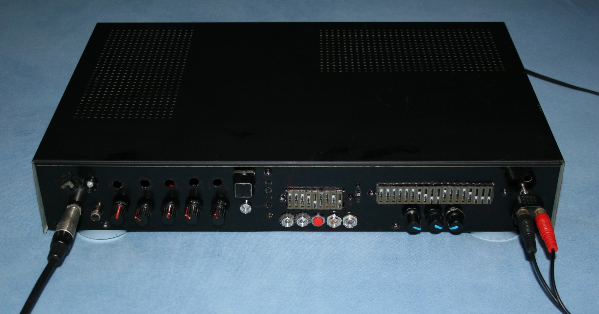
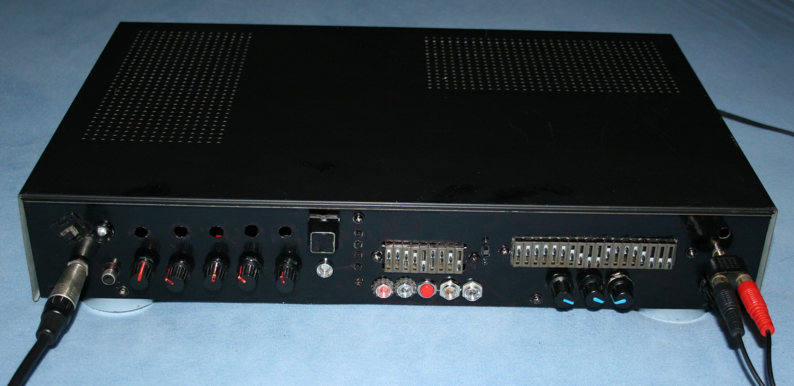
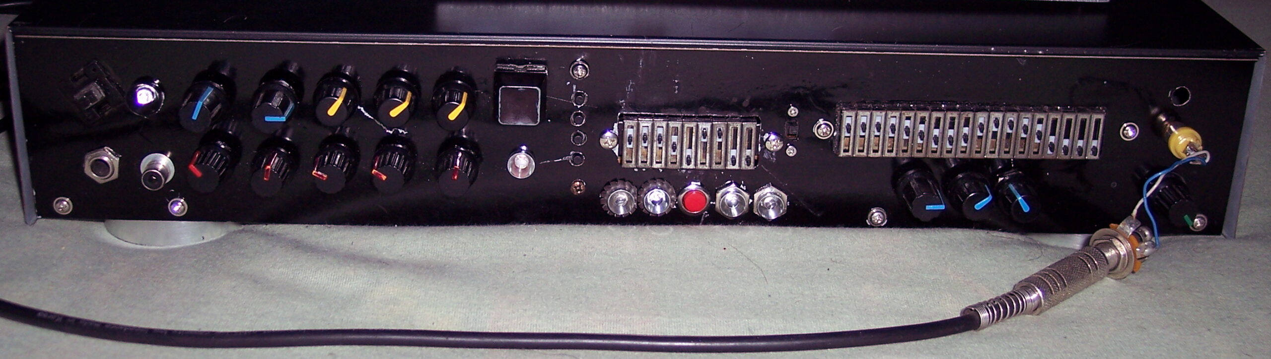
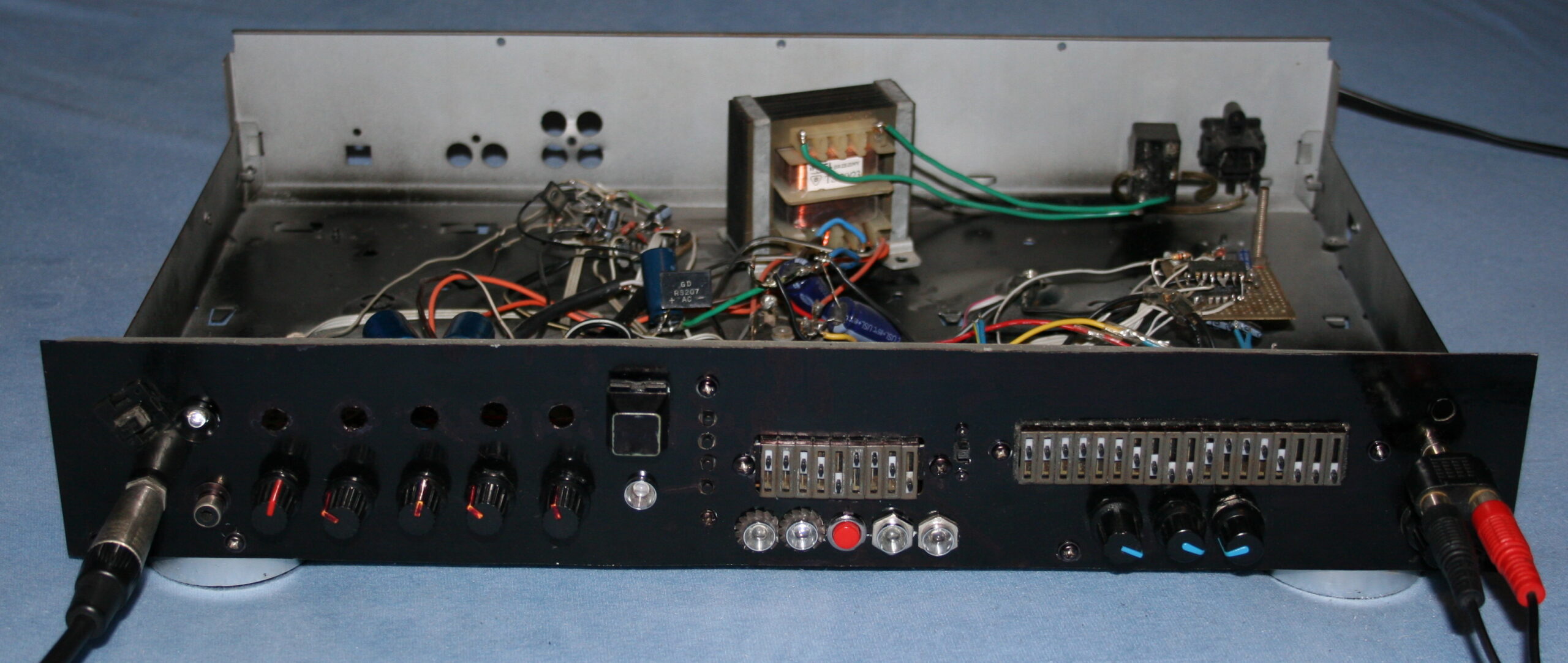
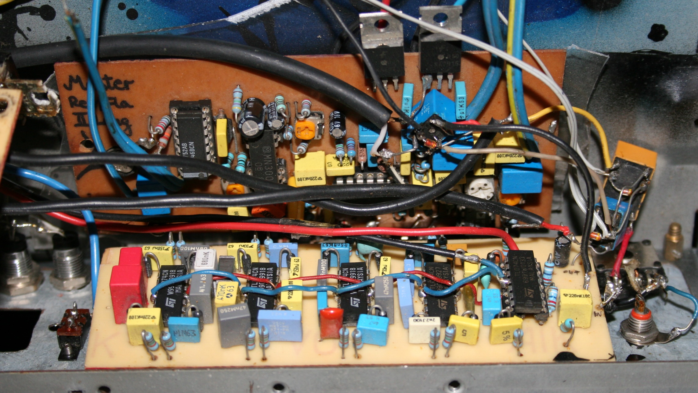
    “Distortion X – The Great” was my final version of an analog guitar effect from 2004, and looked similar in 2003 already.

    📊Features

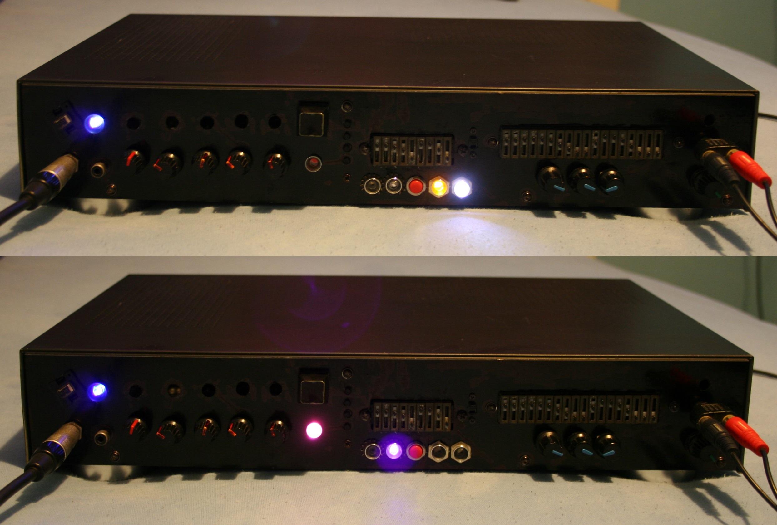
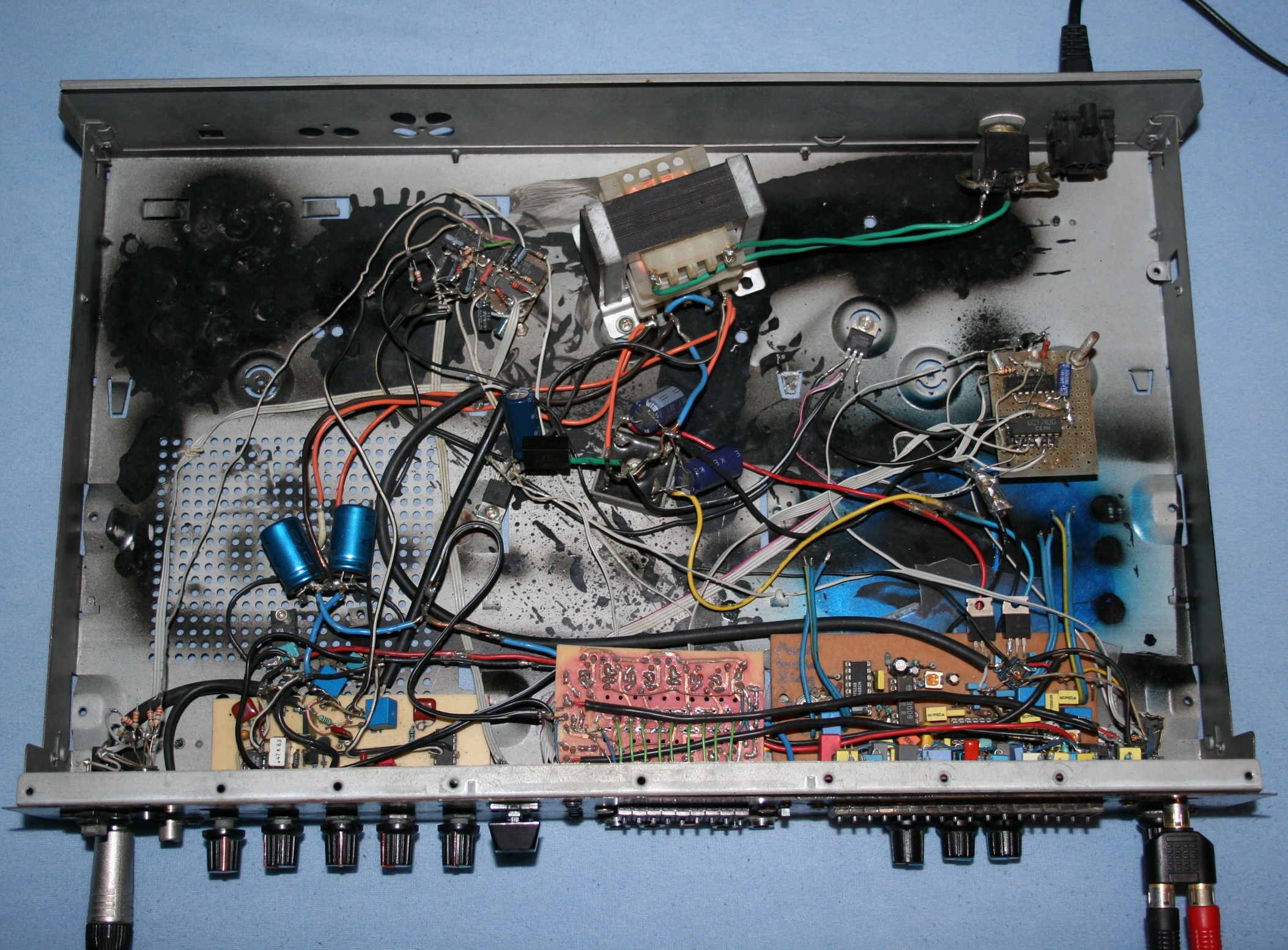
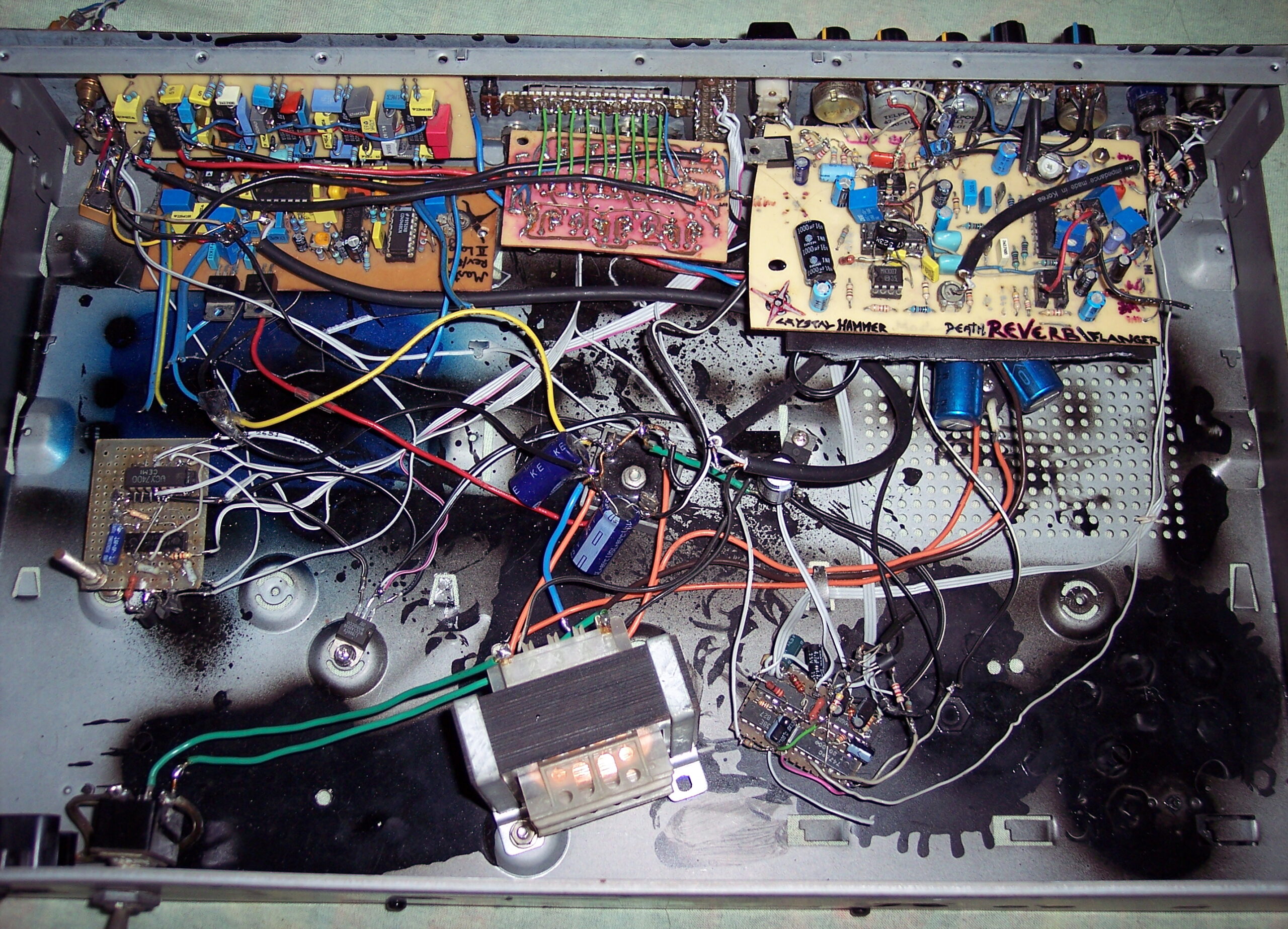
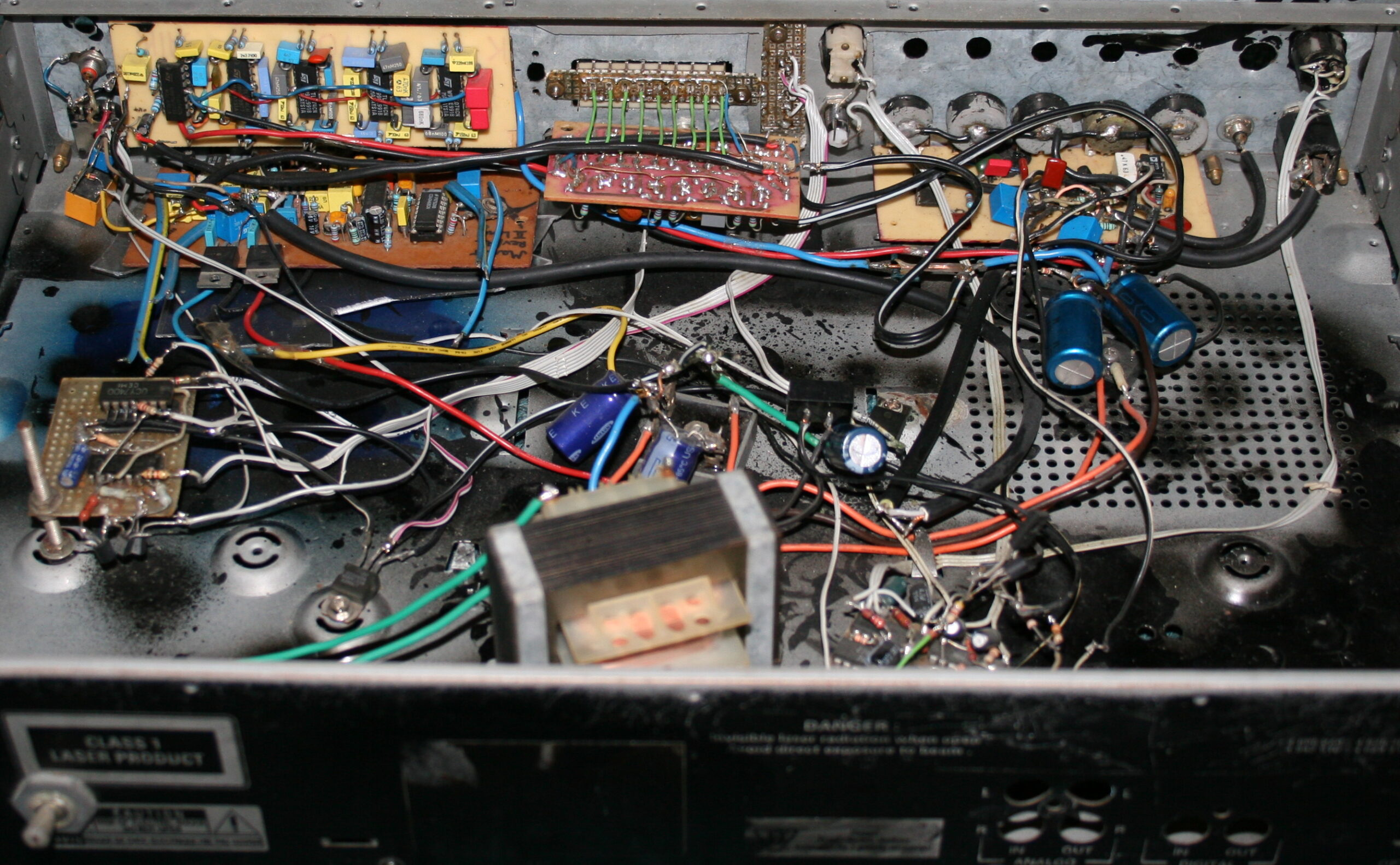
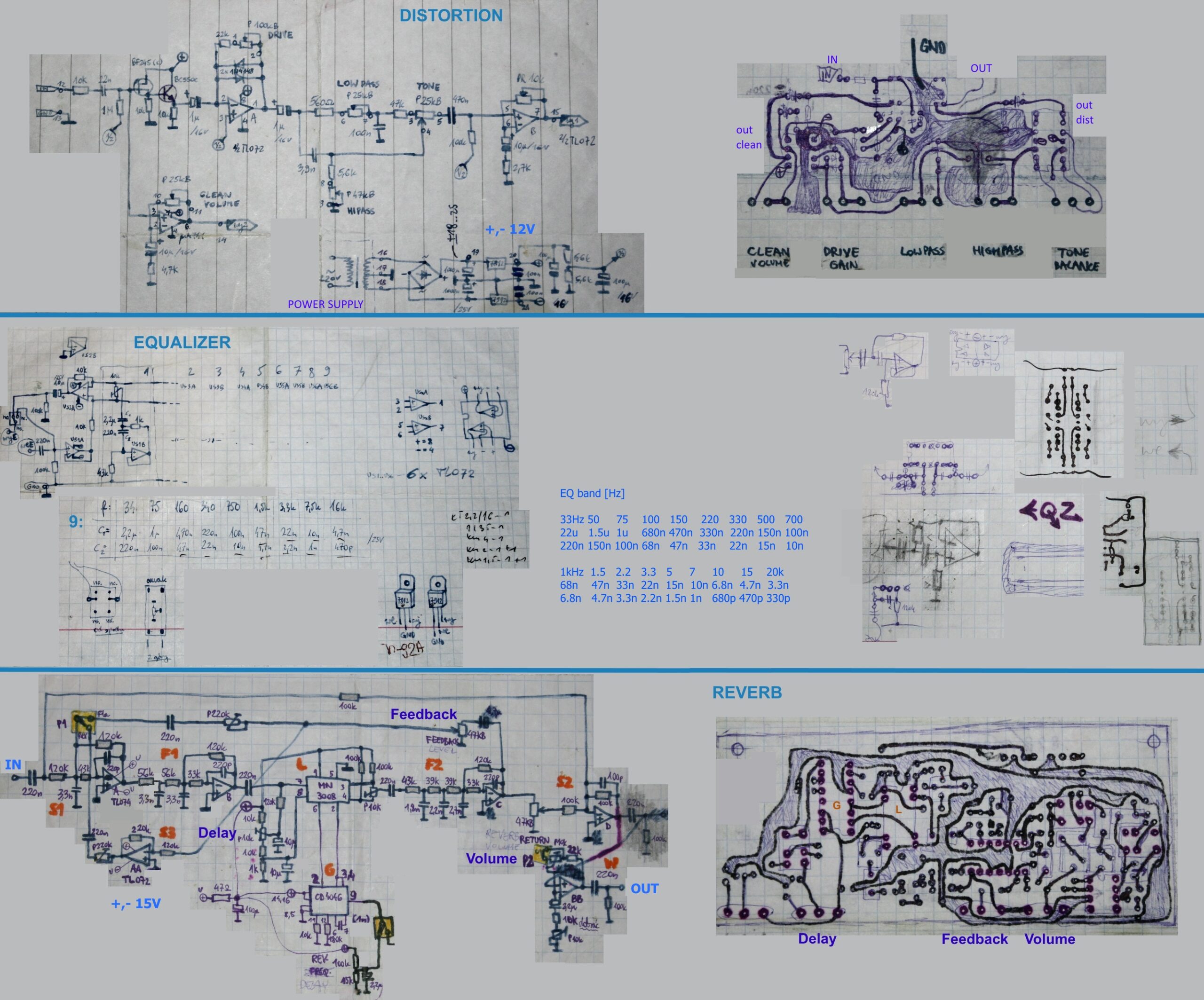
    It had a Distortion, Reverb / Echo and 2 Equalizers (9 and 18 bands).

    The Distortion featured such regulations:
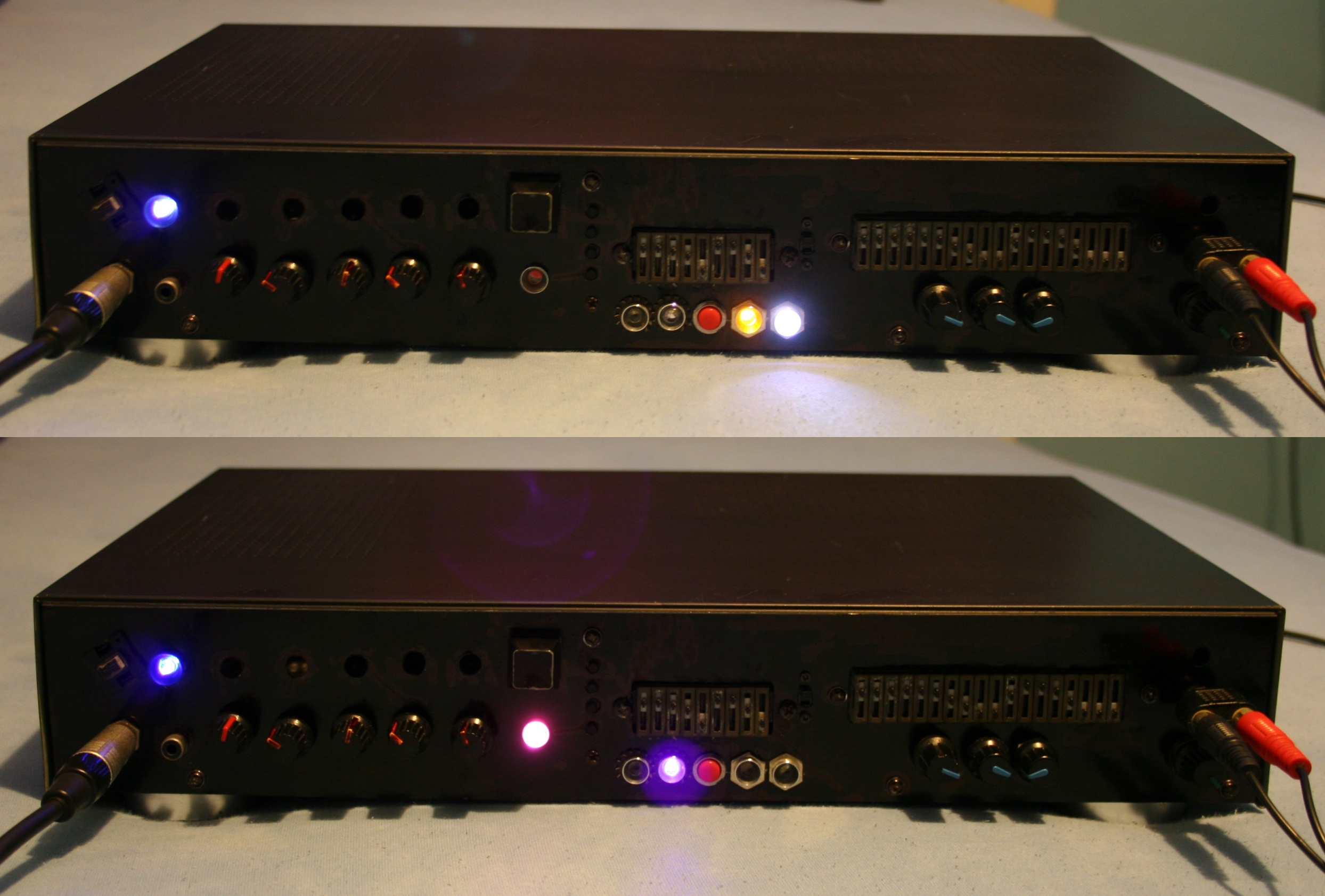
    • Switch for Clean / Distorted mode, pink LED
    • Clean Volume
    • Drive (i.e. Distortion, Amplification)
    • Low Pass (filter frequency)
    • High Pass (filter frequency)
    • Balance (mix between the two filters)

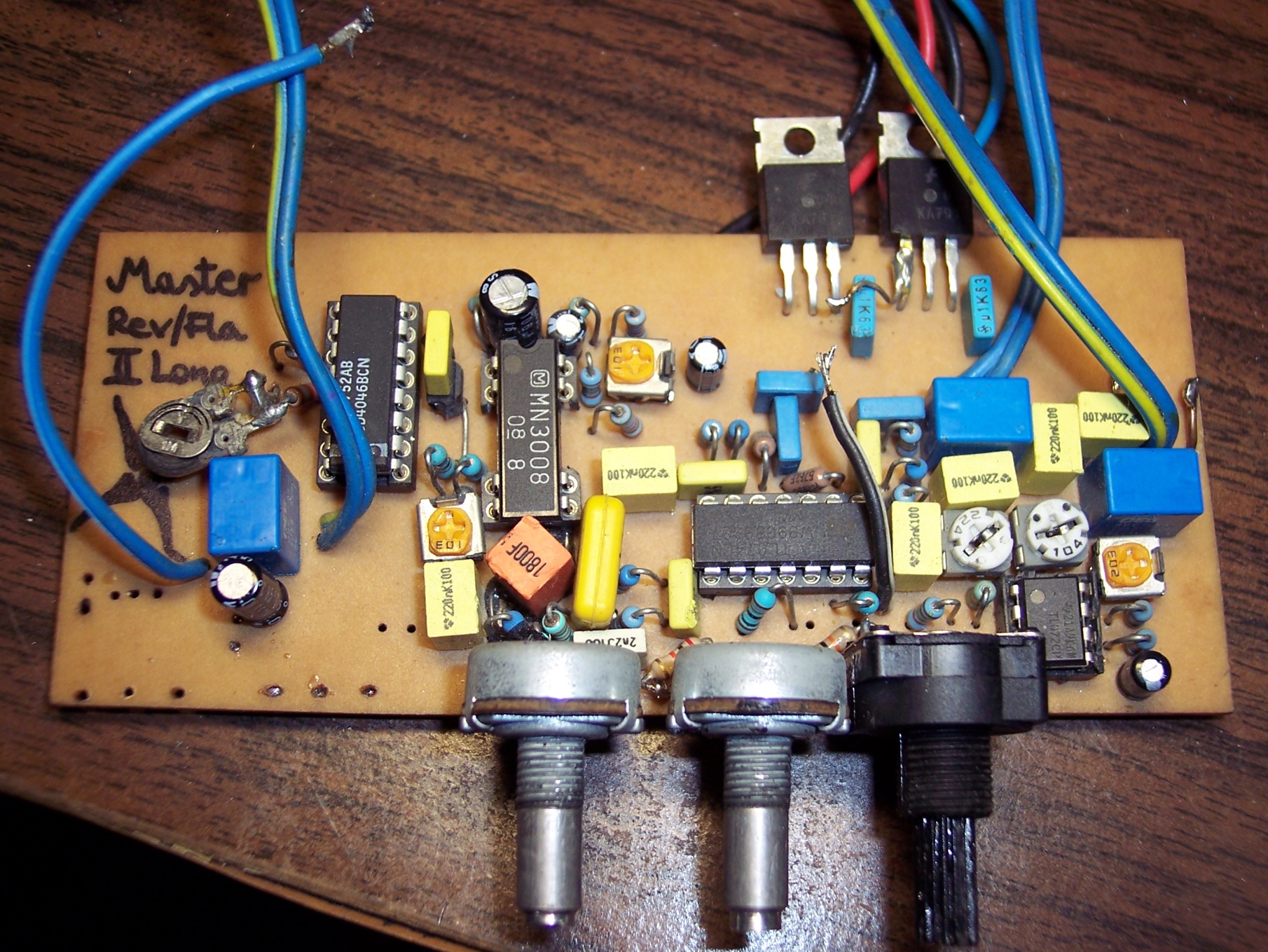
    Reverb was made on the longer analog line MN3008.

    It had only 3 potentiometers (knobs):

    • Delay (i.e. Length: short would do Reverb and long did Echo, at reduced bandwidth)
    • Feedback (how much from output was summed back to input)
    • Volume (output mix between Reverb and clean)
    • Switch to turn on/off, white LED

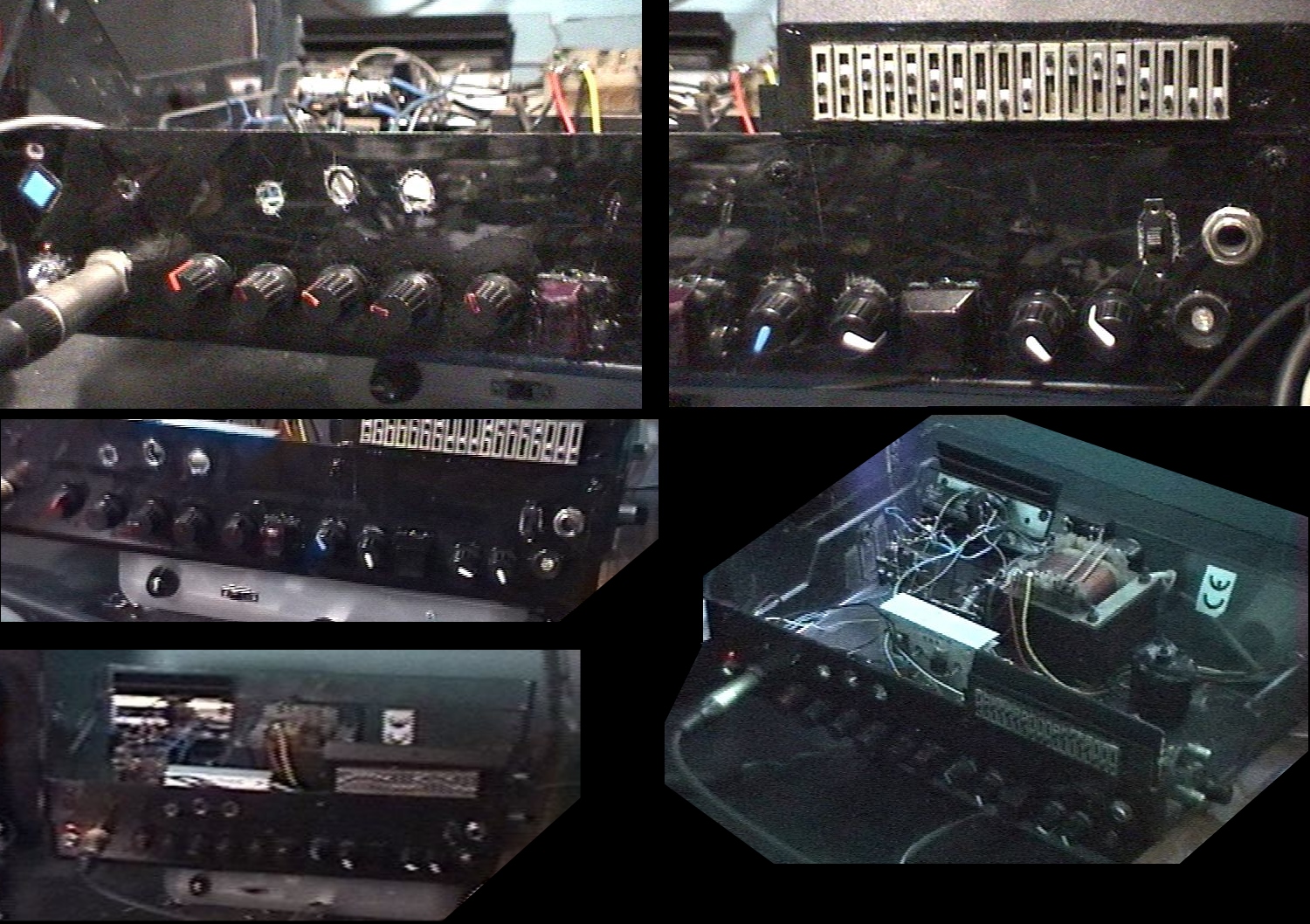
    Equalizers were used only one at once. By default the Narrow one (9 bands) was for Clean mode and Wide (18 bands) was for Distorted, thus allowing more customization. Narrow had violet LED on left, and Wide had orange, on right.

    It also had 2 switched, one would exchange Narrow with Wide (so the opposite to default, Narrow for Distorted). And other switch was to turn equalization off, mainly just to check the difference, most left, red-orange LED.

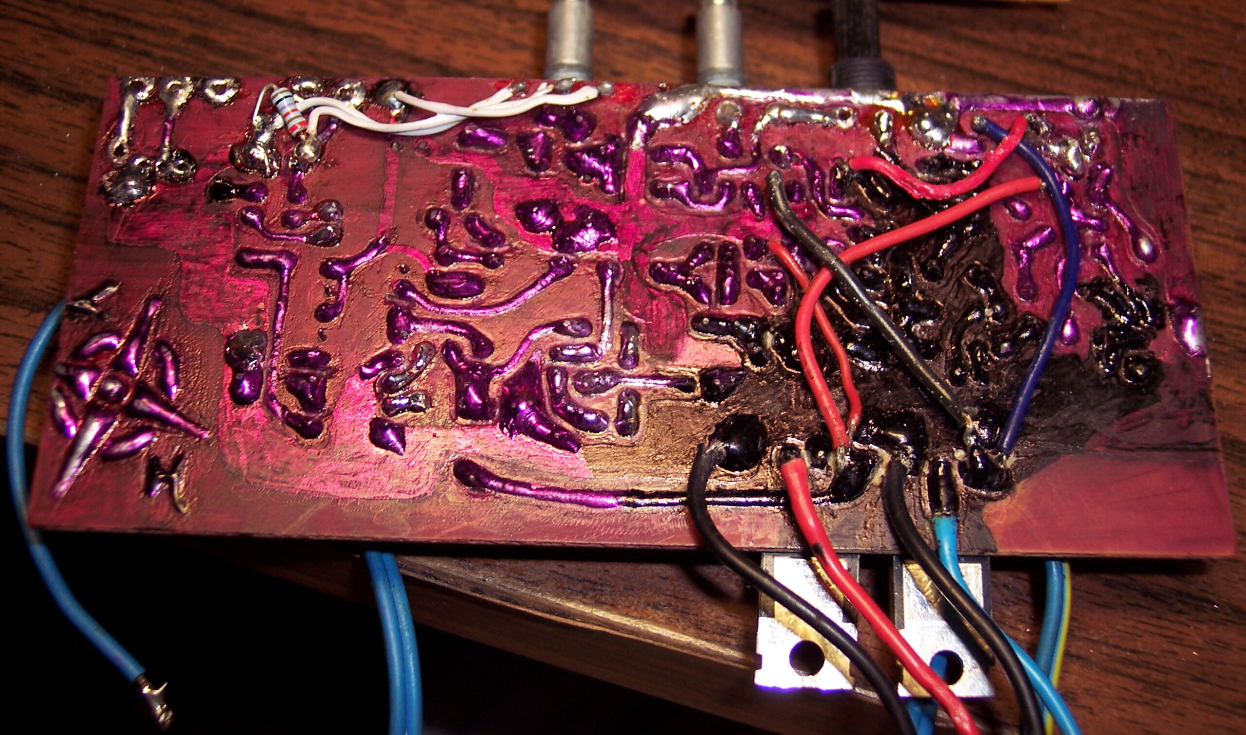
    For a moment it had also the short Reverb / Flanger board with knobs, visible on pictures. But I didn’t use it. Power supply for it was different (not symmetrical) and that added more noise.

    📜History

    I was developing analog effects for electric guitar since we started playing in 2001. There were several versions of it. The 1st was just a distortion. The 5th had one 9 band equalizer and I think also a Reverb / Flanger on short delay line MN3007. The 8th was similar but had 18 band equalizer and long Reverb / Echo.

    Since I was playing backgrounds and my friend solos, we needed 2 effects. The 5th and 8th were separate and best combination. I was naming them using Roman numerals, so this one, X was the 10th and last version.

    ⏳Conclusions

    In 2004 I bought a digital effect, Digitech RP 200A, and first realized the huge difference between analog and digital effects. It was very feature rich and the sound quality was much better (probably like 20dB more, I guess my analog could be about 70dB SNR at best). Digital had many more effects like Chorus, Detune, realistic Reverb, high quality Echo, Cabinet models etc, and was stereo. But that model was very poor in regulations, there was only one parameter for each effect that could be changed (whole effect had only 3 nobs).

    So even though it was higher quality and had more features (but less regulations), I still used my Distortion for some time. Also since the digital sound and because we started college we stopped playing together so often and then at all. Also we had the digital one so I could just put all equalizers and reverbs in one. Then I finished it with a better case (from an Audio CD Recorder, which internals I moved to a worse case).

    ➡️End

    I sold it recently. For a ridiculous price, maybe just summing up to what parts had cost me. But there was a lot of time dedicated to developing it and making PCBs. But still, I’m glad I freed up cabinet space and didn’t have to throw it out (too sentimental to do that). Also got some money for it and somebody could find it useful or maybe even educational. I sold my guitars that year too. They were just gathering dust for too many years.

    It was great for what it was. It was the best I could make of what was possible at the time. Recently I thought a few times already, about how much easier and more advanced a digital effect processor could be made. For example Teensy 4.0 has a lot of power, ADC and DAC are available nowadays as codec chips rather cheaply and Teesny seems to be popular for music devices and similar projects. Maybe even slower MCUs could that earlier. Earlier I have even searched and found an already open source guitar effect, I forgot which was it, but searchin now gives even more results.

    📷Gallery

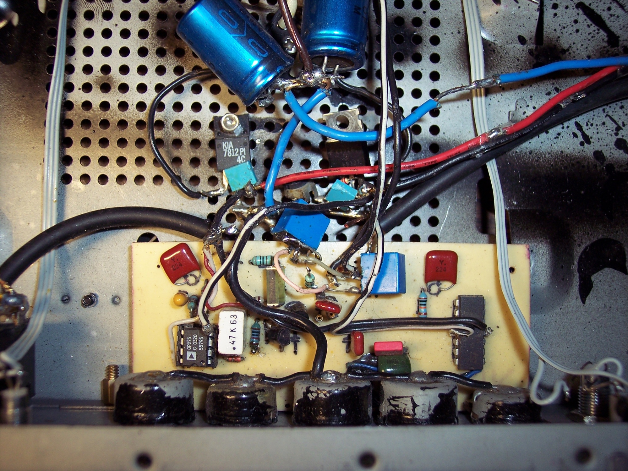
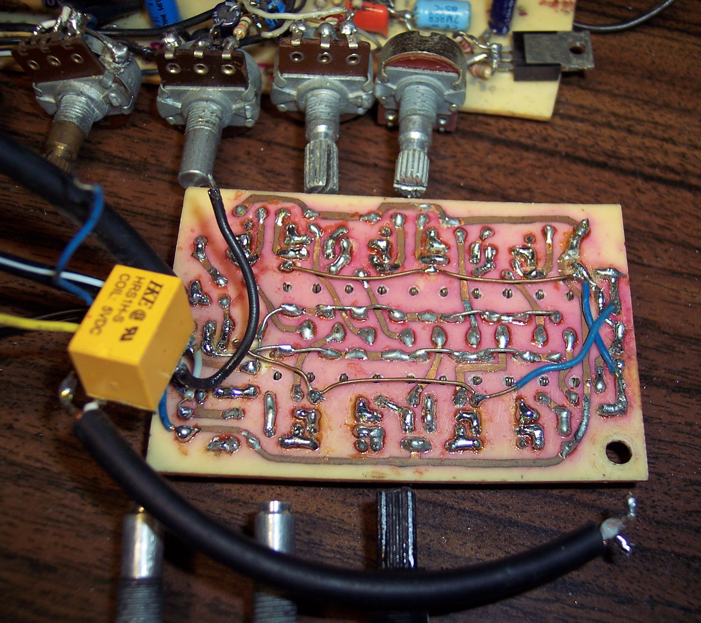
    Also with pictures of inside and schematics.

  • 2002-03 Console 8051

    2002-03 Console 8051

    ⏱️Overview

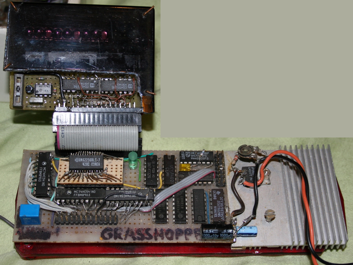
    This is the final version of the “console” I created around 2003. Its purpose was to serve as program memory for 8051 MCU (board with it is not yet attached on this picture).
    The PC was filling console’s memory with bytes of code and then starting MCU which used it as program code.
    Console was connected with a PC through parallel port (LPT). The PC had my own IDE (editor) and compiling its assembler code to bytes.

    Nowadays this isn’t at all needed and even looks scary. MCUs of today have Flash memory for program, either programmed from PC through USB already or with a simple chip (USB to serial) converter/adapter/programmer.

    📊Features

    PC usually was sending a lot of bytes, so the console had counters, to increment the address by itself.
    It used power supply from PC, here 12V which LM317 regulator converted to 5V.

    So its memory (SRAM, 256kbit) was filled by the PC through the console, it then would serve as program memory for the 8051 family MCUs (a quite popular one, but still poor, like ATmega328 today).

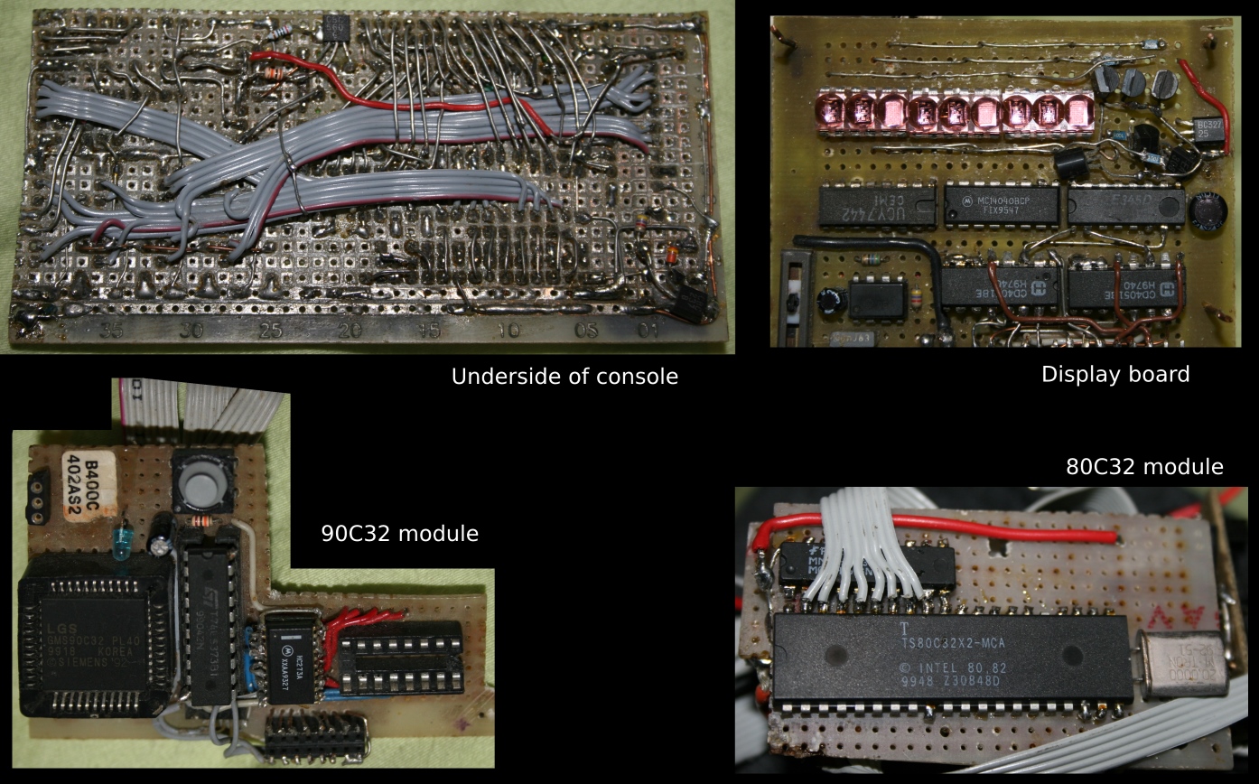
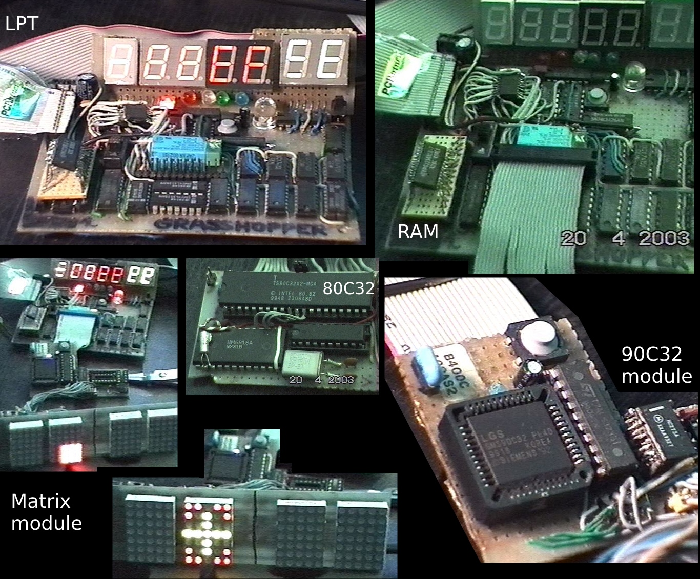
    I had two modules for it. One with big 80C32 and second with smaller and faster 90C32. The console had a connector where you could attach one.

    It also featured a relay that would automatically turn on the supply for the module once the program got transferred to memory.

    Later you could switch the SRAM to EEPROM and get it programmed for the use in actual module/device with MCU, without console. Which I eventually never got to.

    🔍Details

    The console board was smaller than the older one (below) and needed less current. It featured a small and detachable display module, for showing address and byte value, which was mainly for checking and later wasn’t needed.

    Construction was made on a universal board, possibly reused. Since being smaller it also was more durable and had less spaghetti wires. Underside actually looked very well compared to the mess in older version.

    🖥️Program

    The PC program was driving LPT port and sending code bytes to memory. It quickly became a basic IDE, where I could write code for ’51 MCU in its assembly language. I wrote it in Delphi 5, which I was using at that time a lot. It translated all instructions and computed jump offsets. Additionally with one key press it compiled assembly code to bytes, then sent it to console and triggered its relay to start the program with MCU module. That was the most convenient thing possible. I’ve seen too many solutions which needed pressing reset switch on the board or other slow, manual work.

    ⏳Conclusions

    I was trying out few things to get done, an 8 bit ADC, a real time clock HM6818A chip and mostly 5×7 dot matrices. It somehow didn’t feel too stable, and it was a lot work to get anything done at the time. I actually didn’t finish any board then, as a separate working MCU. For a clock it would use too much current. And for making anything else that MCU was too slow. And I was more interested in other things at the time like creating music and my tracker.

    📜Older version

    The first (even older) version had bigger digits, mounted solid with also the logic to decode them. I think it was using close to 1A from 5V, and the 74192 counters were heating like crazy.

    I was also using SMD chips, if I found them somewhere else and desoldered. I don’t have any picture from underside of this old version, but I remember it was a serious spaghetti. I’m guessing around 400 wires connected 😆.

    I also made an older project before this console. It was a clock with few cool fonts on 4 small, red, 5×7 matrices. I made fonts just by programming memory and using tiny switches. And the clock had many 74 series chips used, no MCU. Yeah those were the oldest times.

    ➡️Nowadays

    Lately everything I wanted back then, can be way easier (and cheaply) done with modern MCUs connected through USB. I can’t even, when I remind myself of this project, and the trouble needed back then to program a basic and slow 8bit MCU like 8051.

    Hence in recent years my interest got back into electronics and my first keyboards had a 128×64 display, then a 160×128 later and now 320×240 in newest. I thought of using those 5×7 Red/Green LED matrixes again few times, but eventually I didn’t. Nowadays LCDs are cheap and easy to use with any MCU. So it’d be too much work and way less resolution. Even today’s LED matrixes use a dedicated chip. I didn’t even use them for my latest clock, it was still simpler to use an LCD, which can have way more detailed fonts.