Category: Gallery🖼️

Has a pictures or screenshots gallery.

  • 2005 Keyboards CK1,2 ⌨️

    2005 Keyboards CK1,2 ⌨️

    ⏱️Overview

    This is an older topic with less information, just for history purpose. If you’re interested see my newer keyboards or the newest ones, with more explanation, own controller and display.

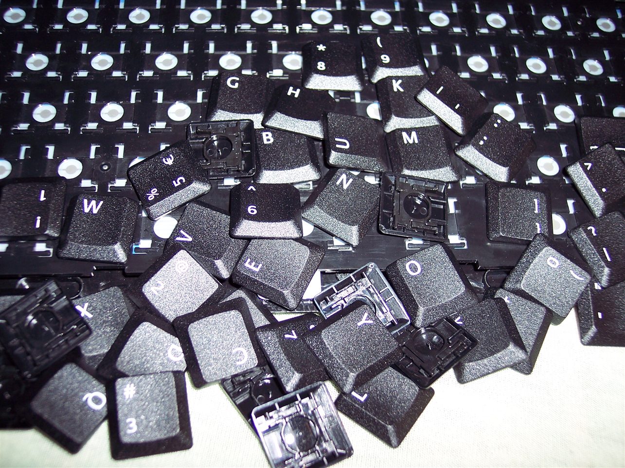
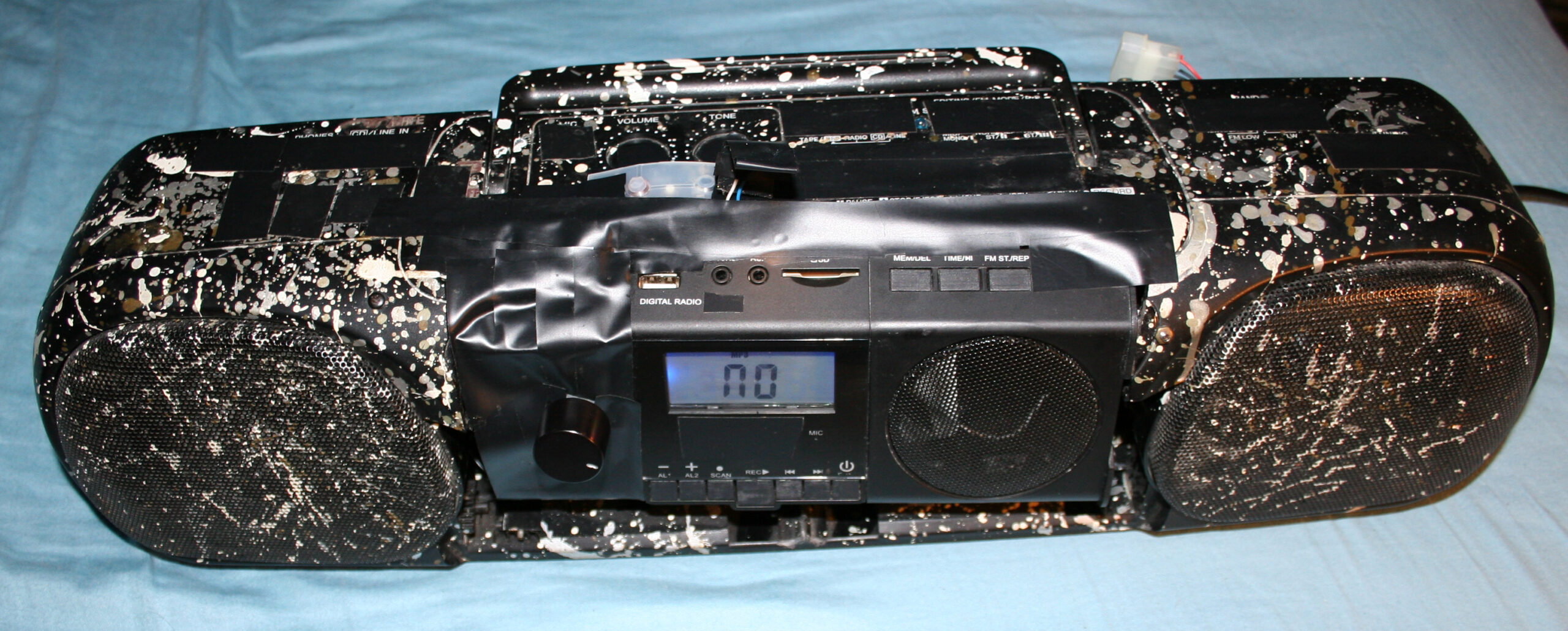
    These were my first modifications for keyboards.

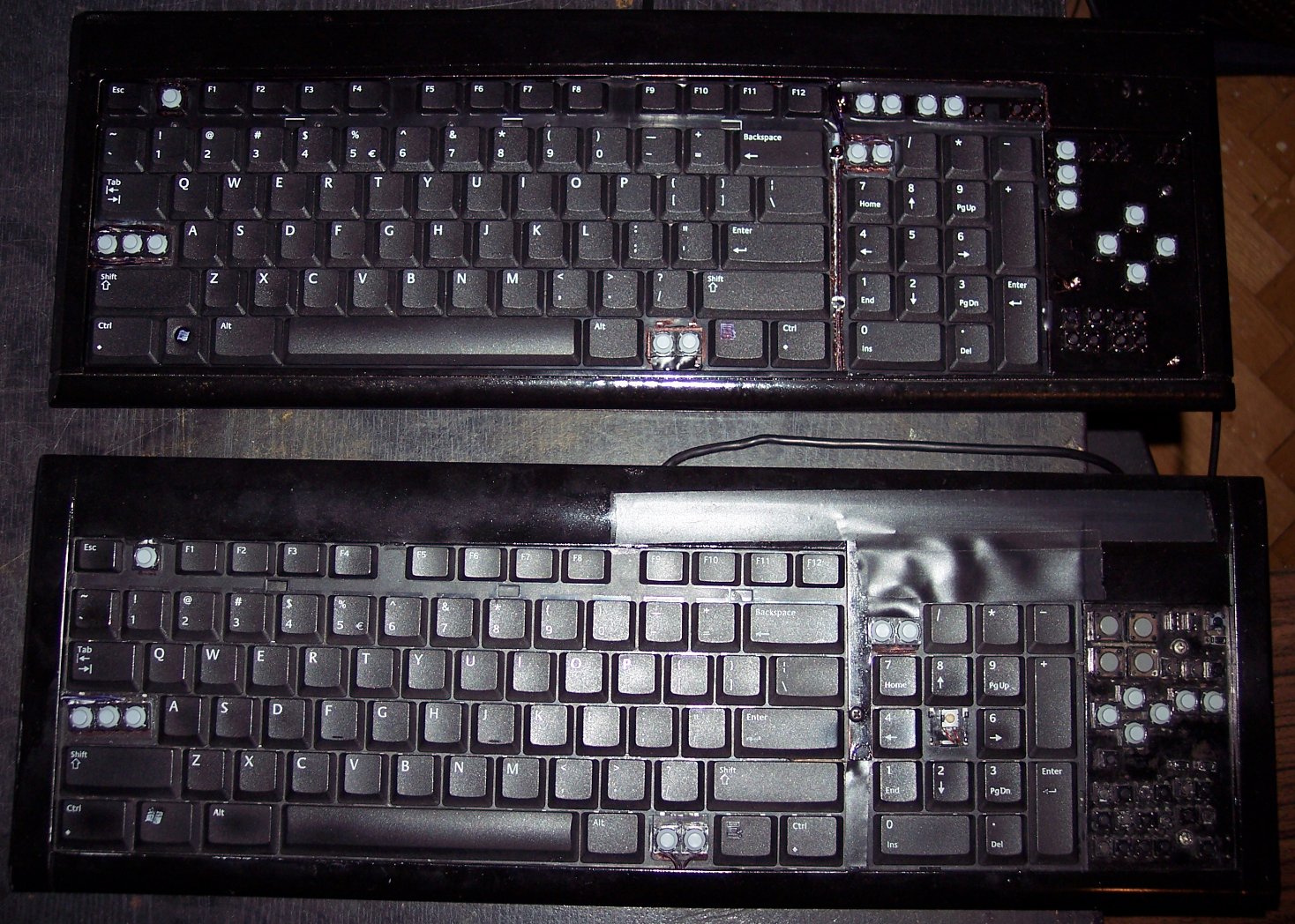
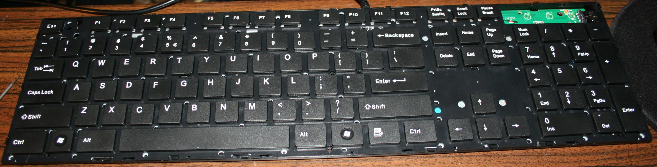
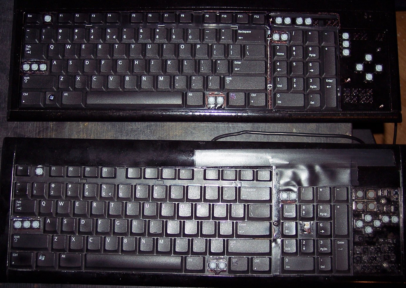
    They were both done on a Logitech Ultra X Flat, a well done, solid keyboard. Surprisingly different for same model made after 1 year.

    ✍️Motivation

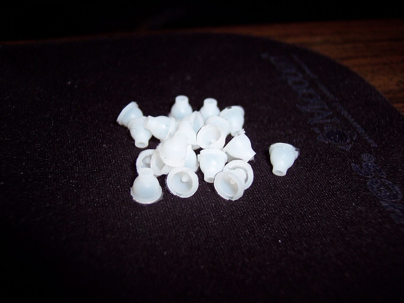
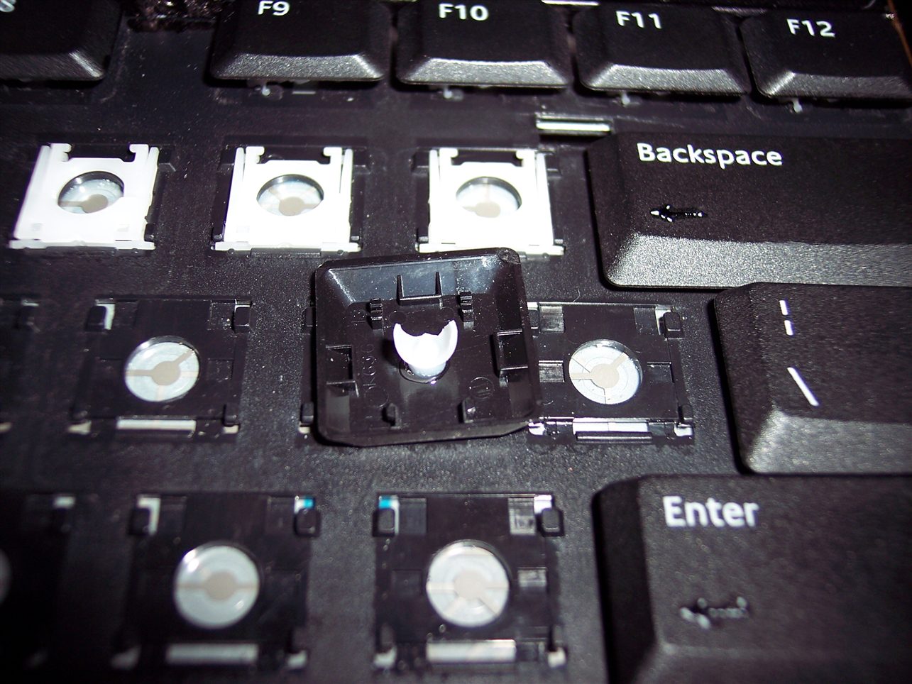
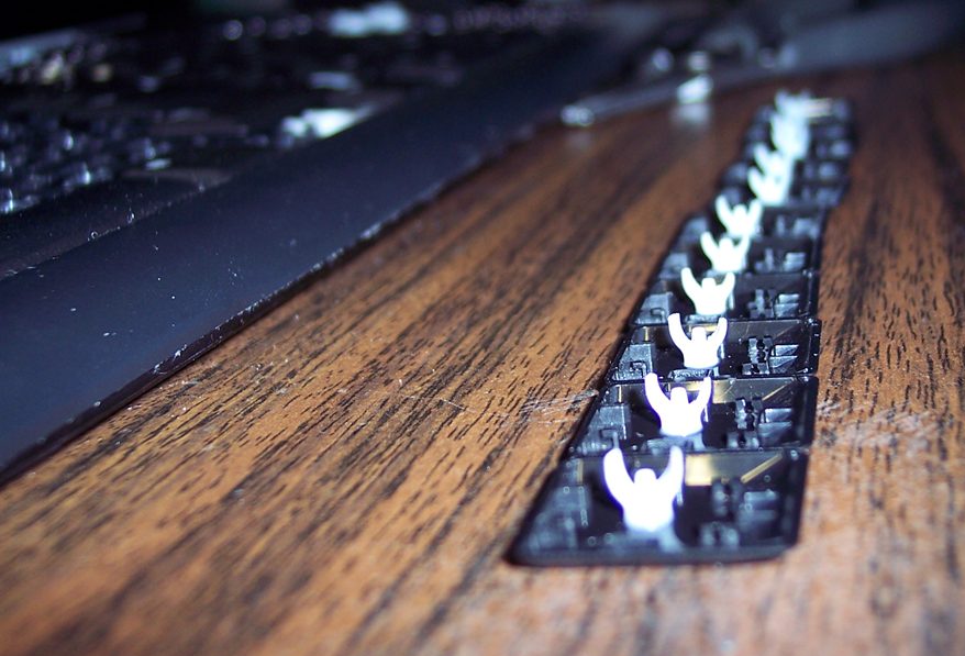
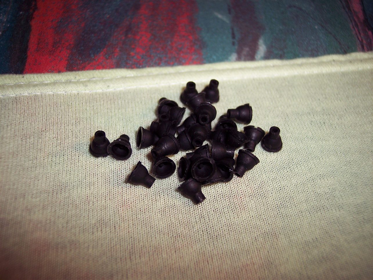
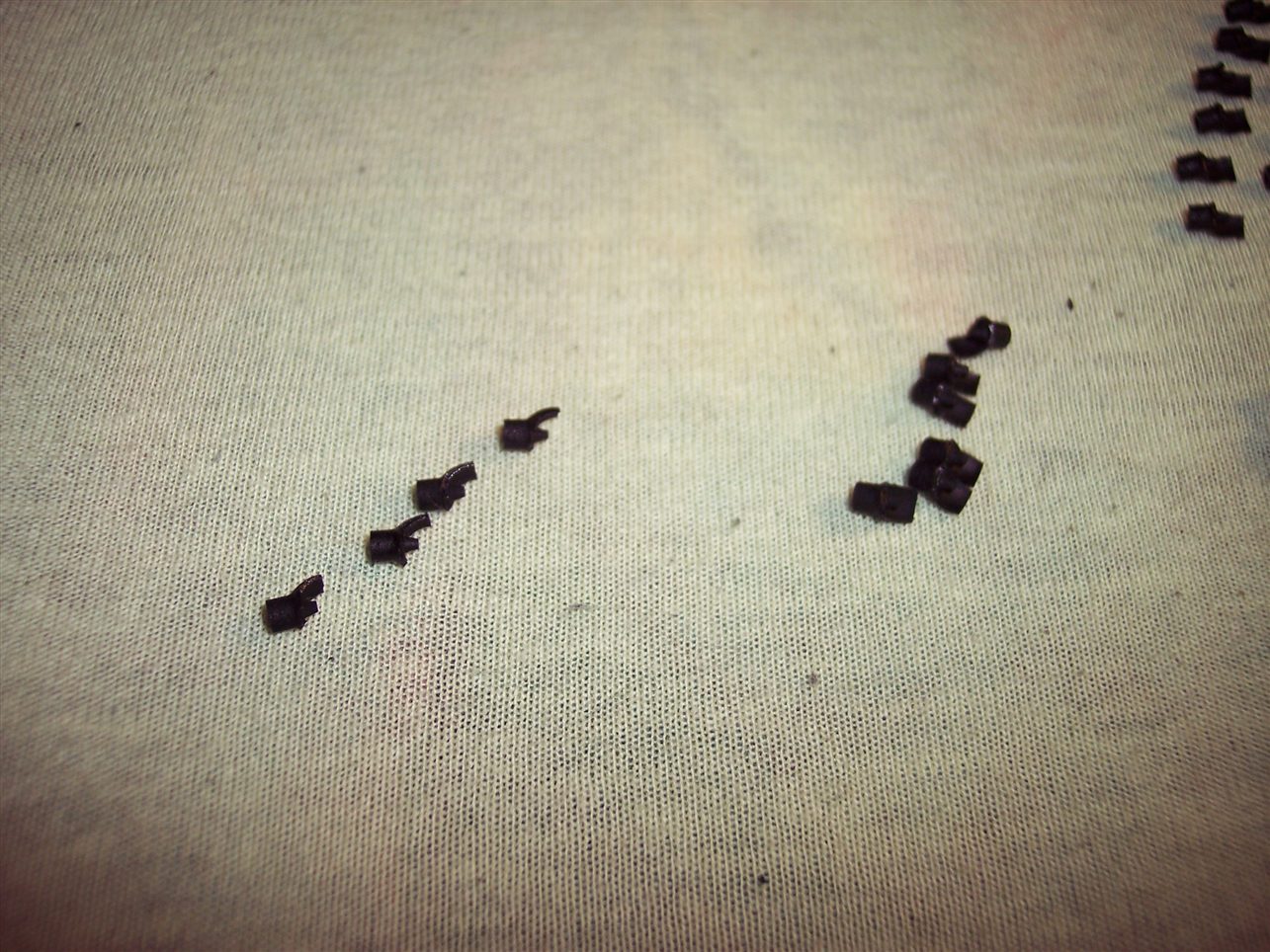
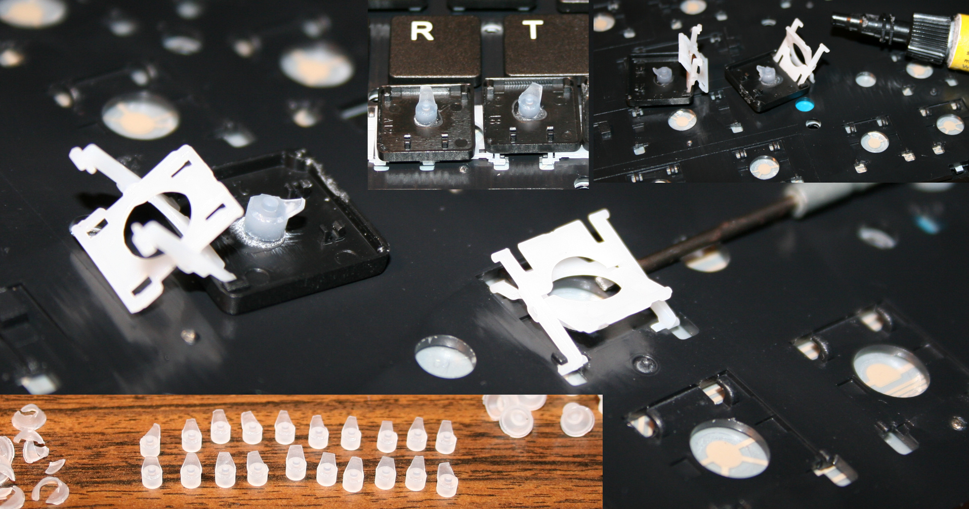
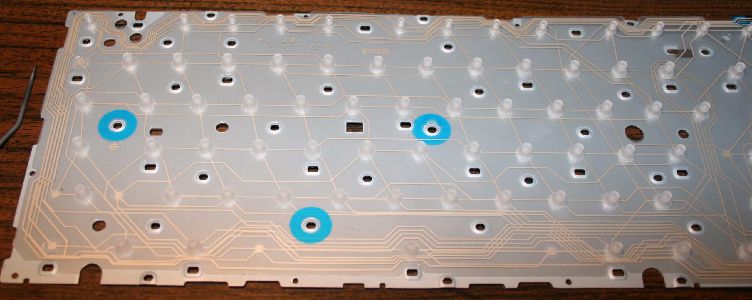
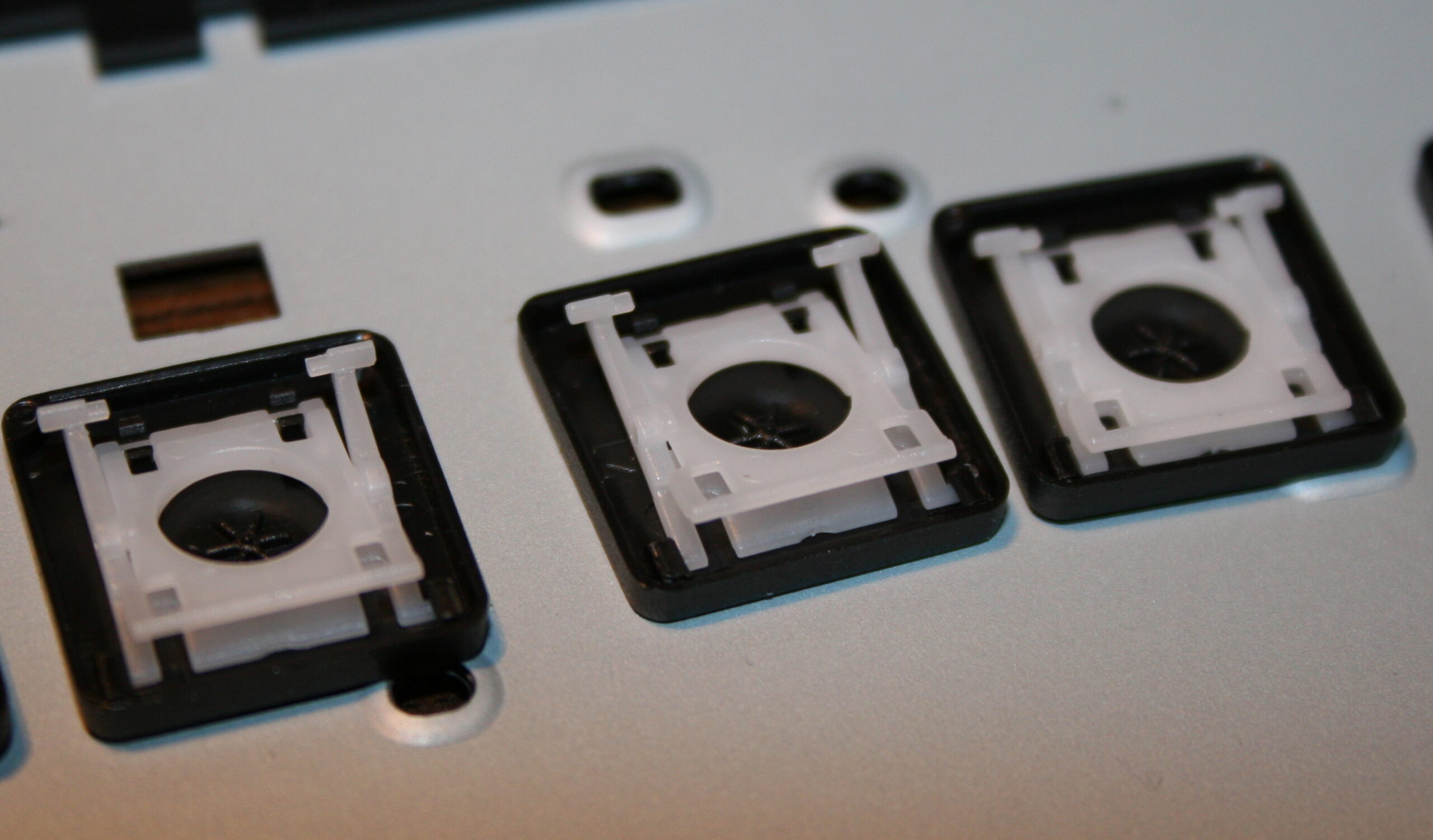
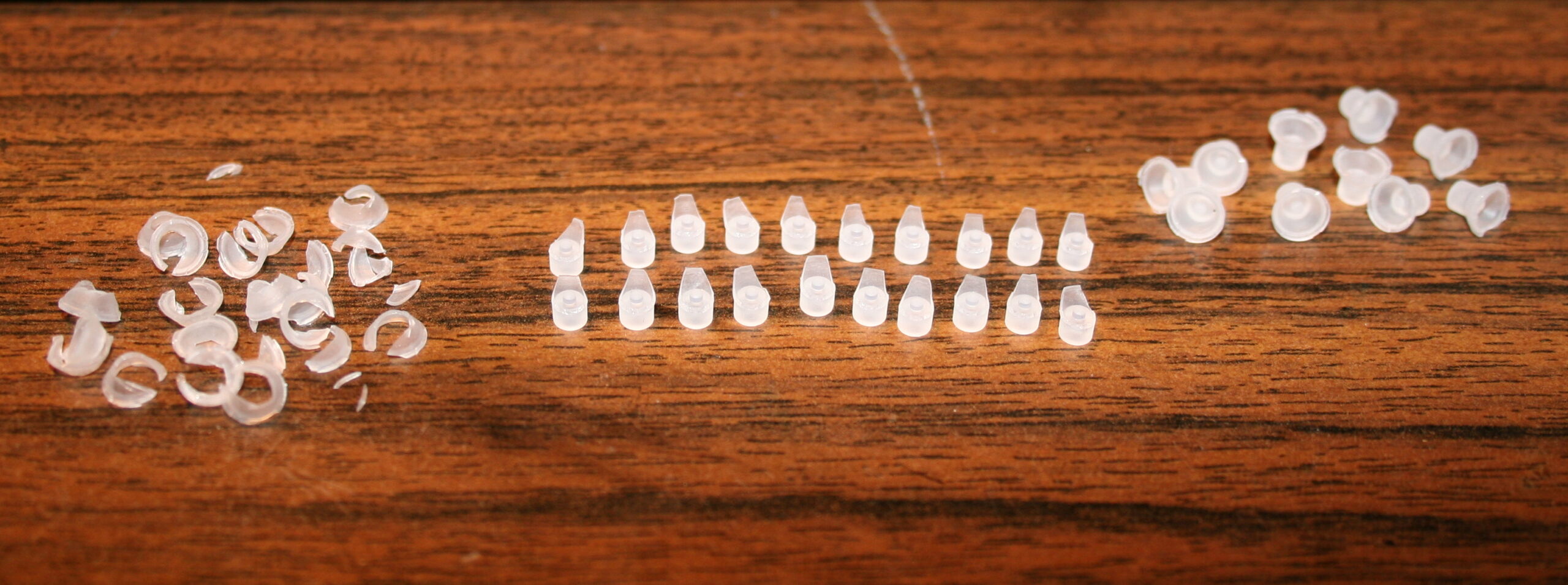
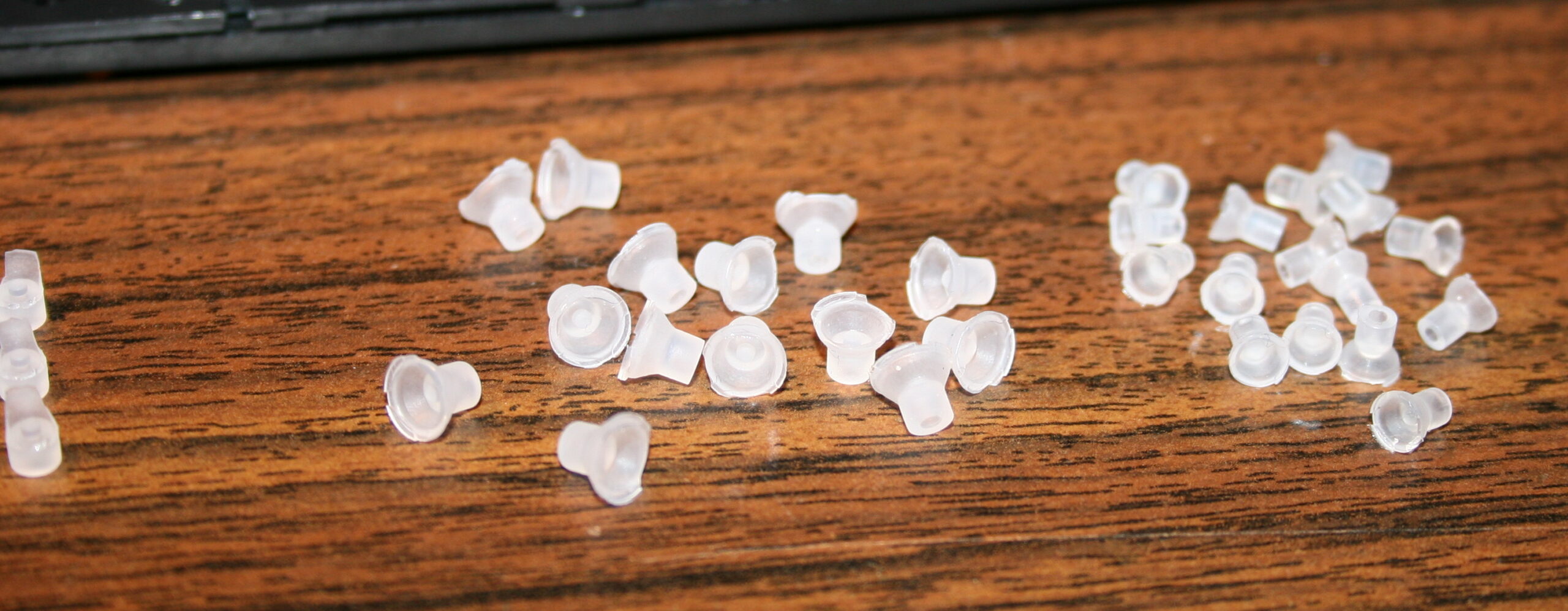
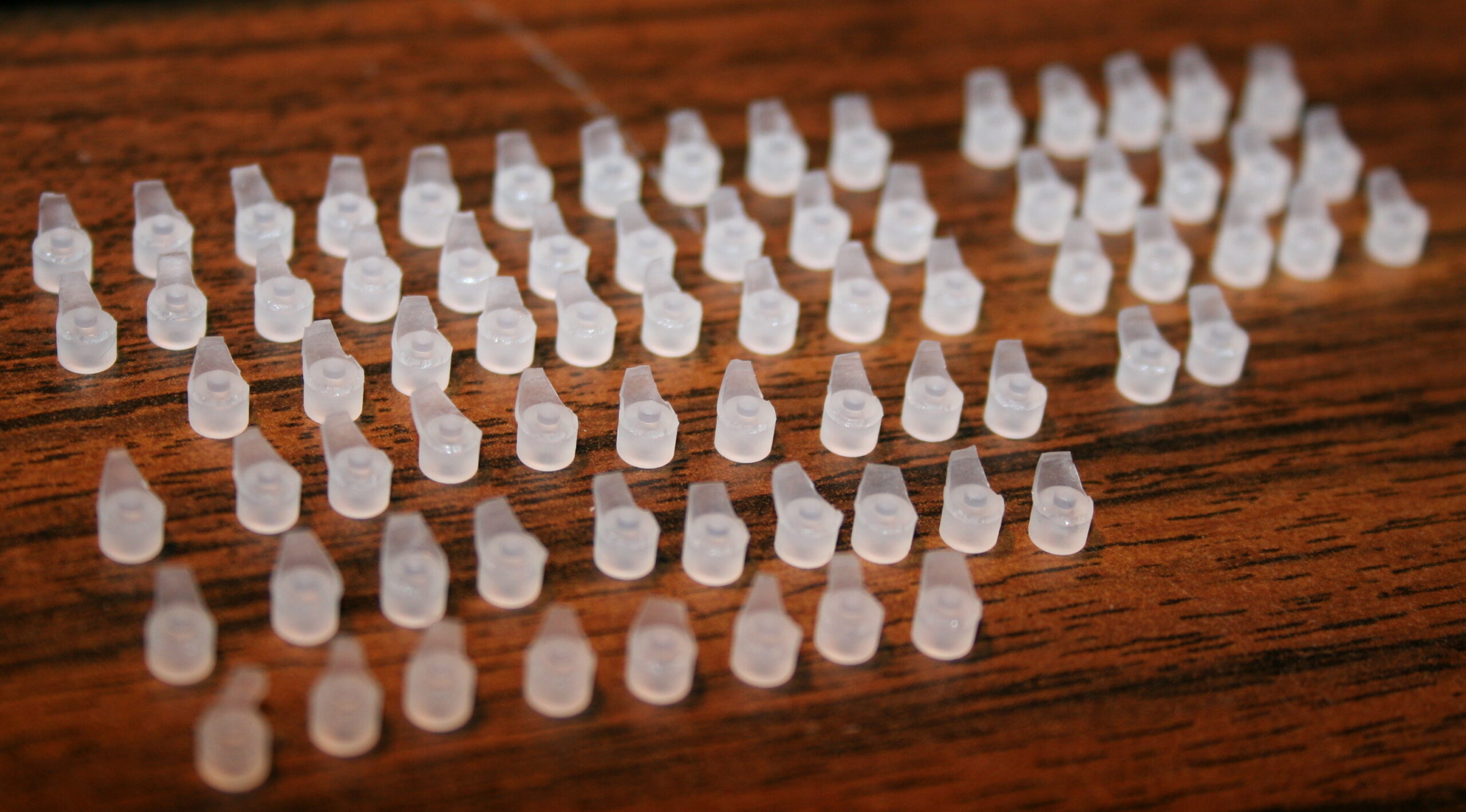
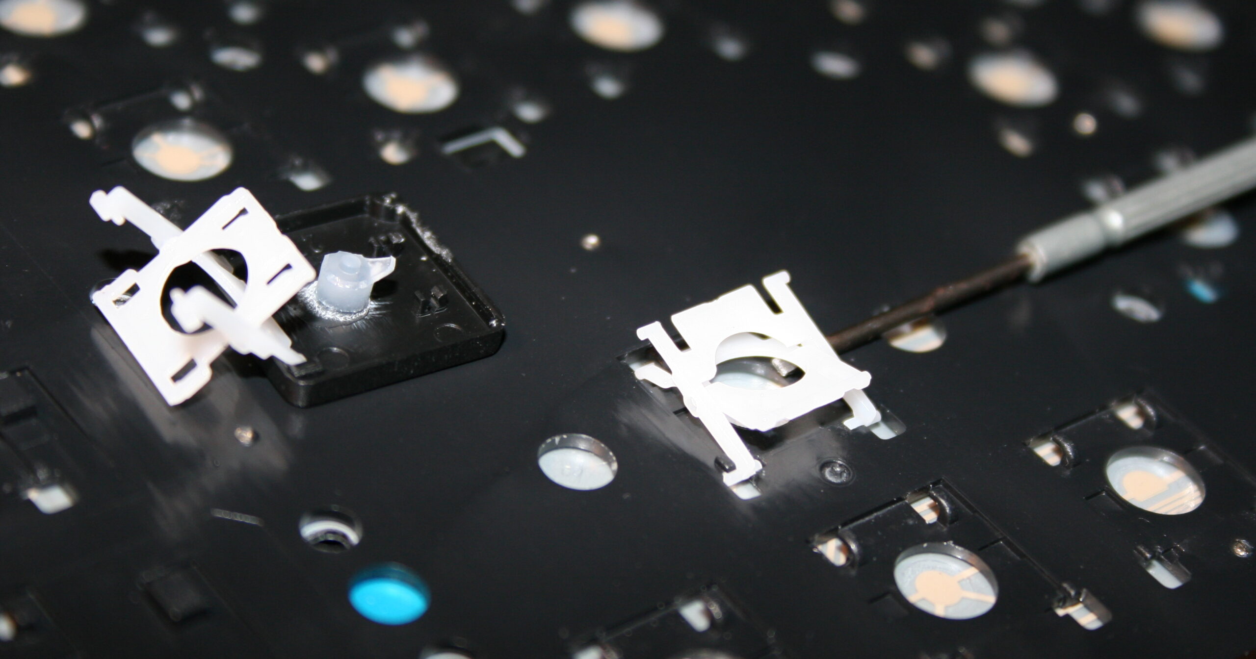
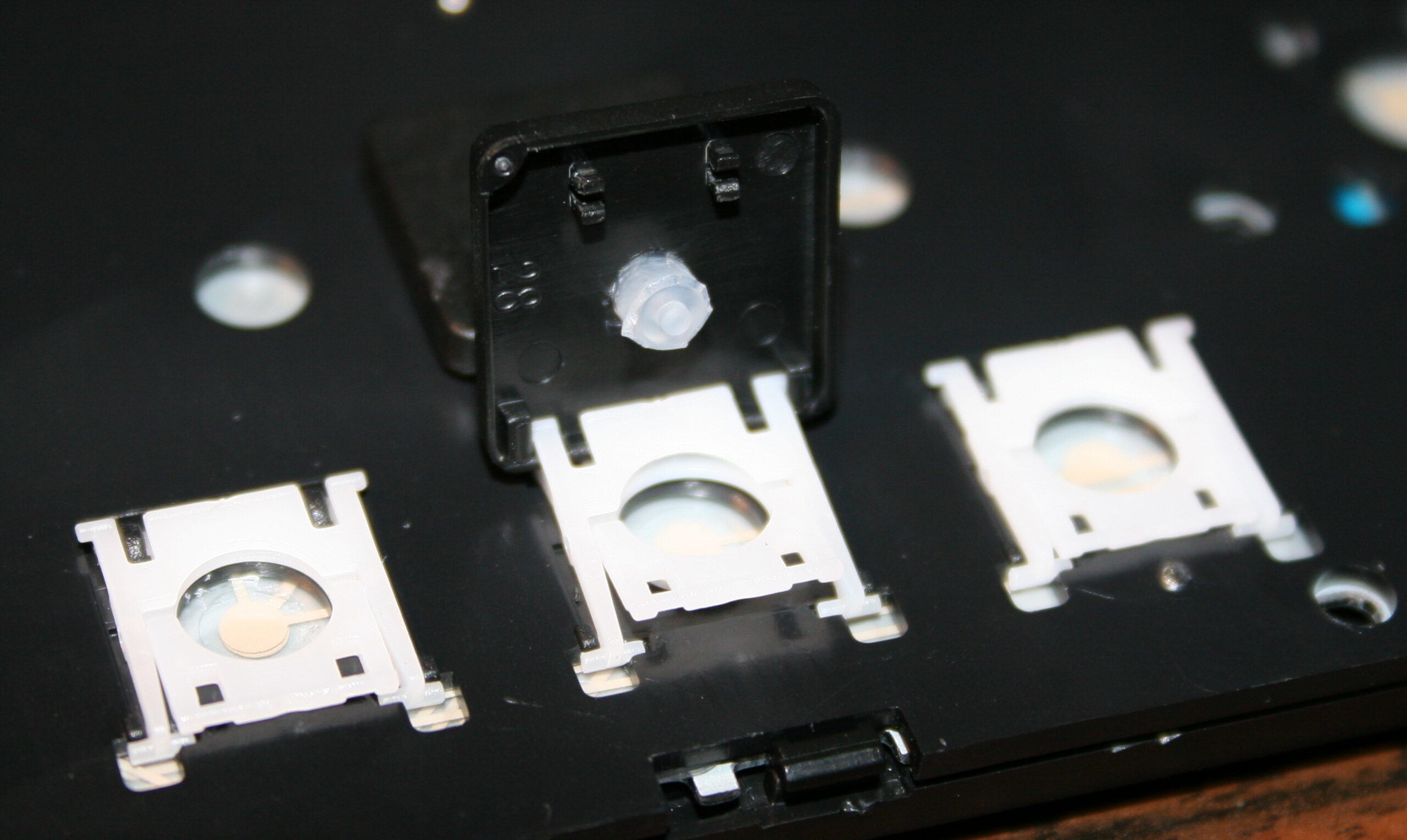
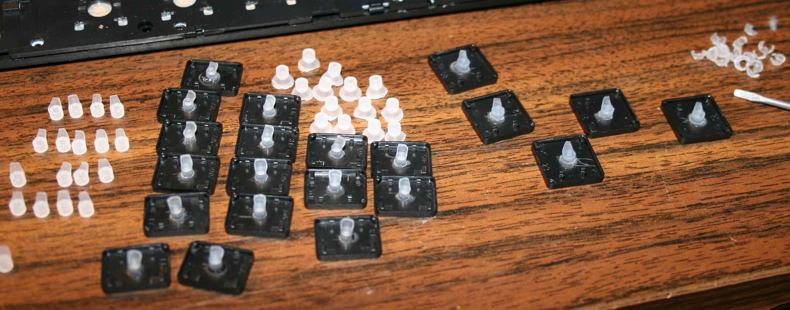
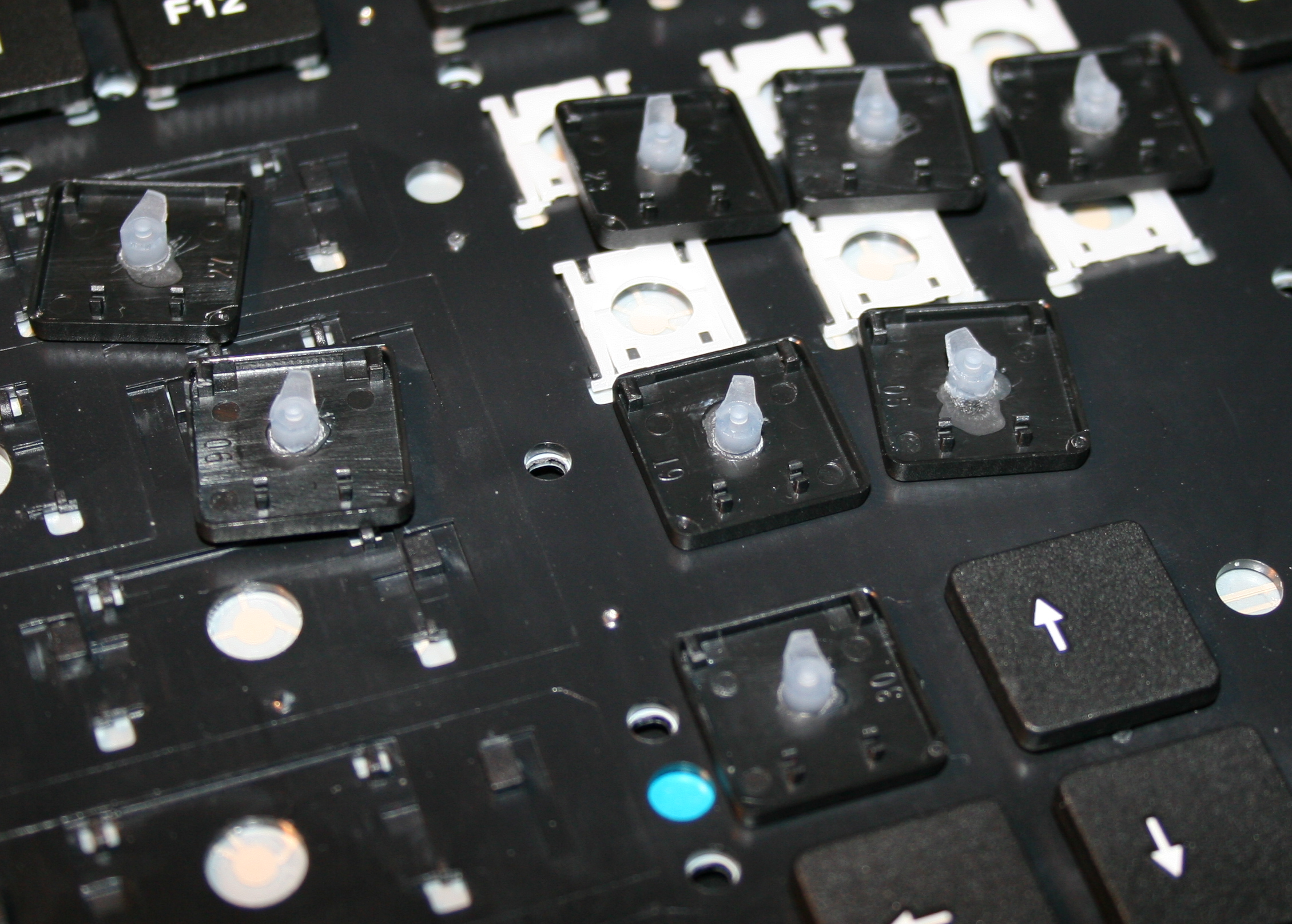
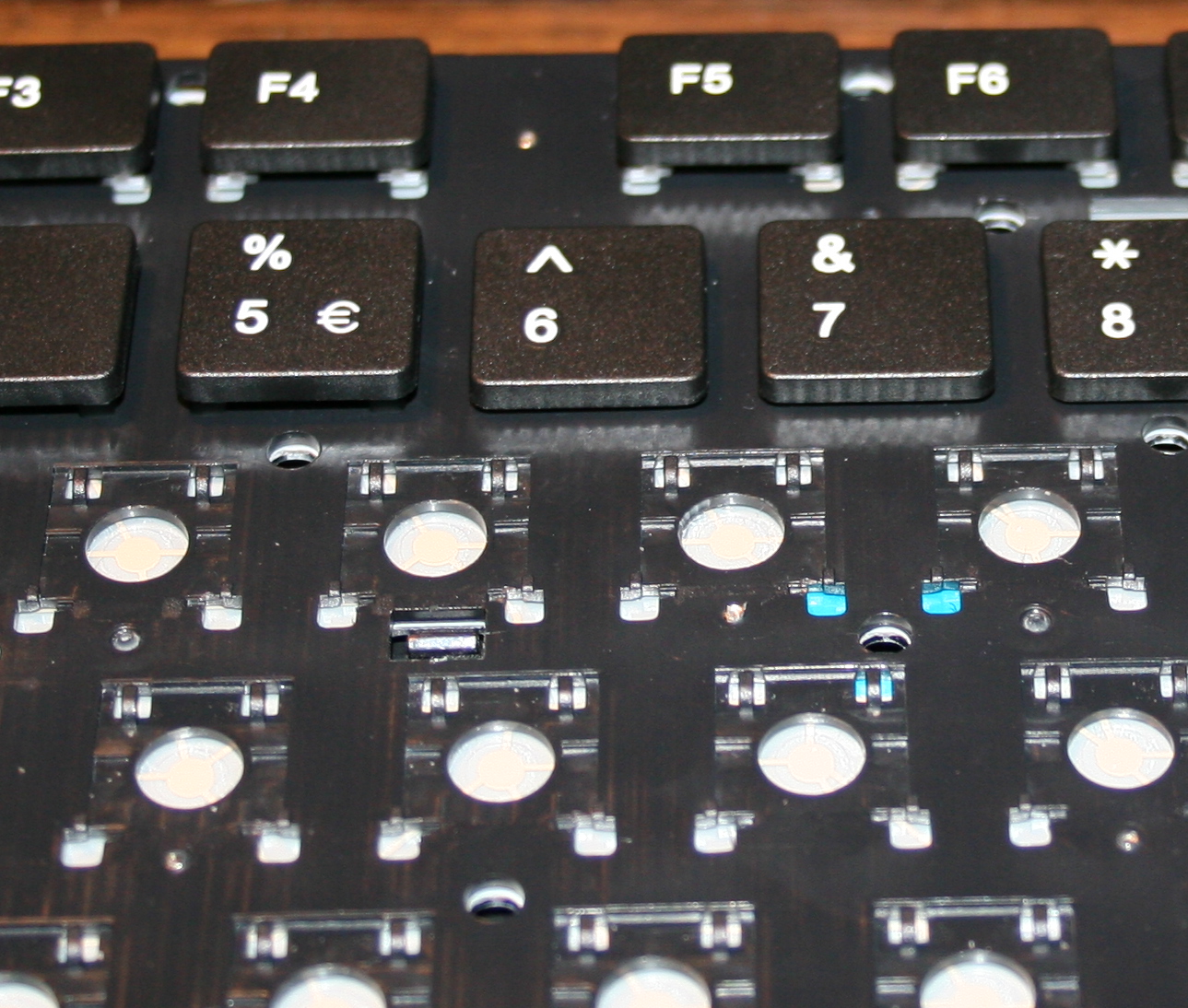
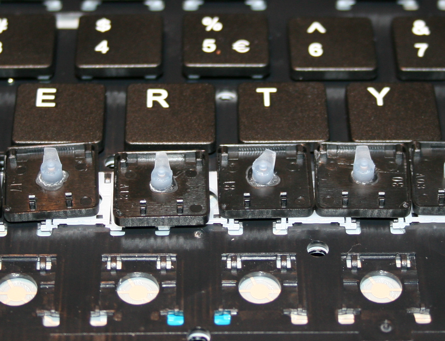
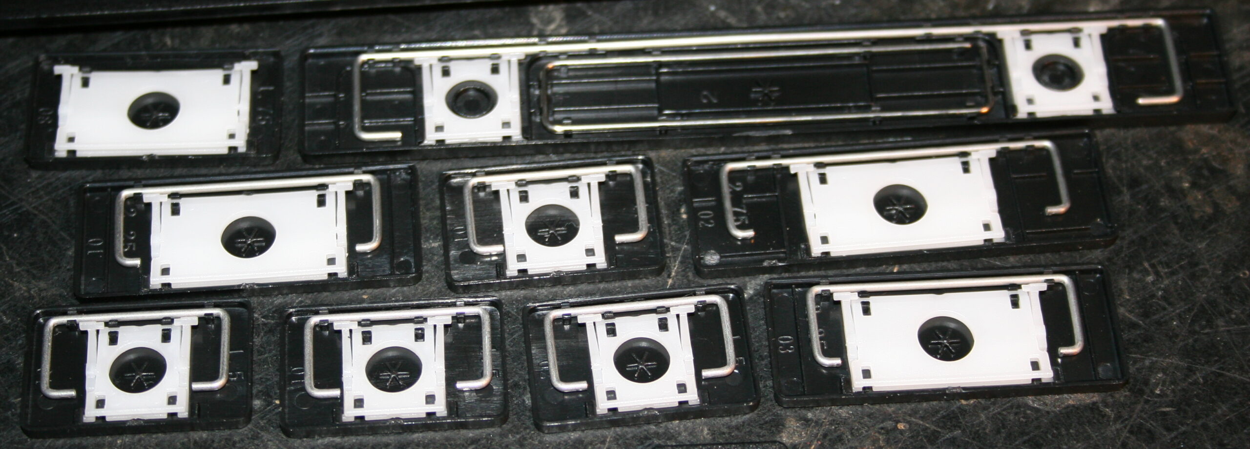
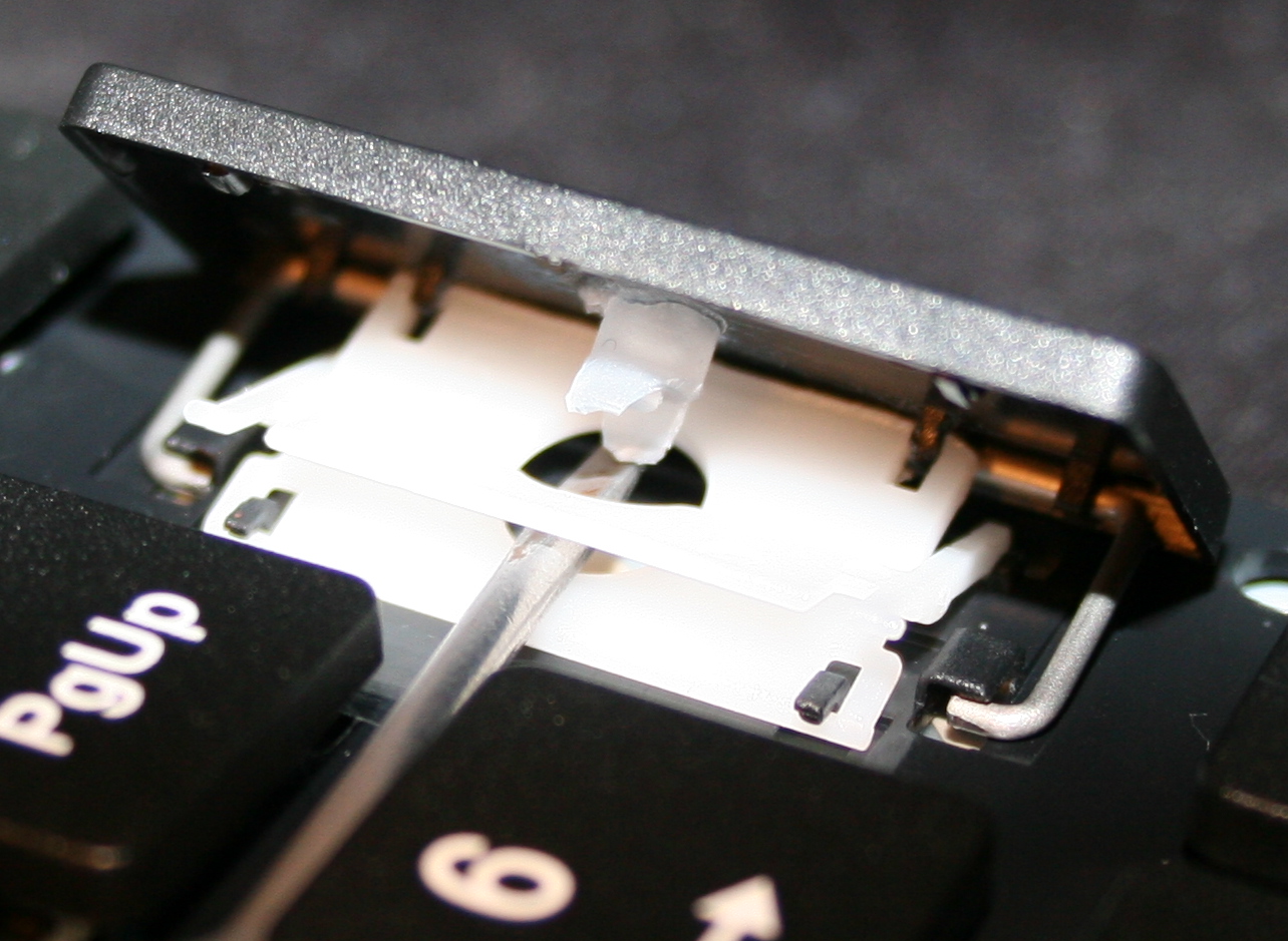
    Originally most keyboards have about 50 gram force needed to press keys, and probably 4 mm distance. After first step of cutting rubber domes the distance is about 1-2mm, the force was about 22 gram for CK1 (bottom) and 33g for CK2 (top). This can also be varied per key.

    📊Features

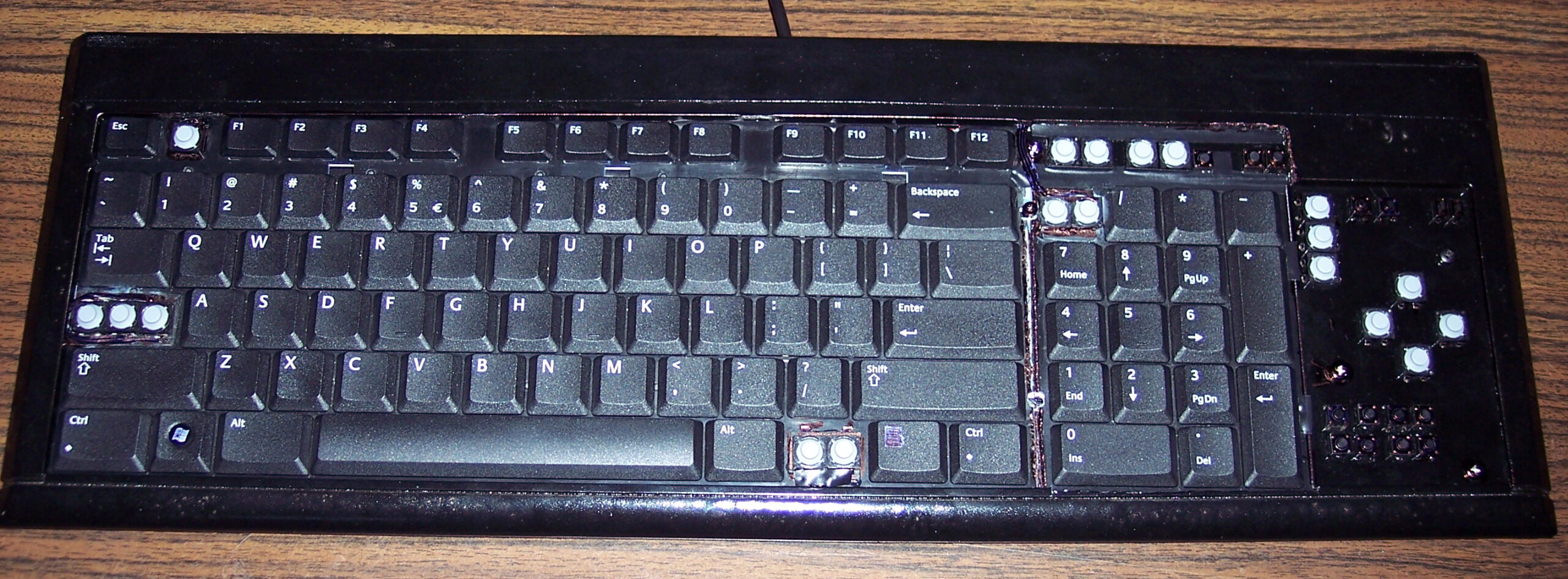
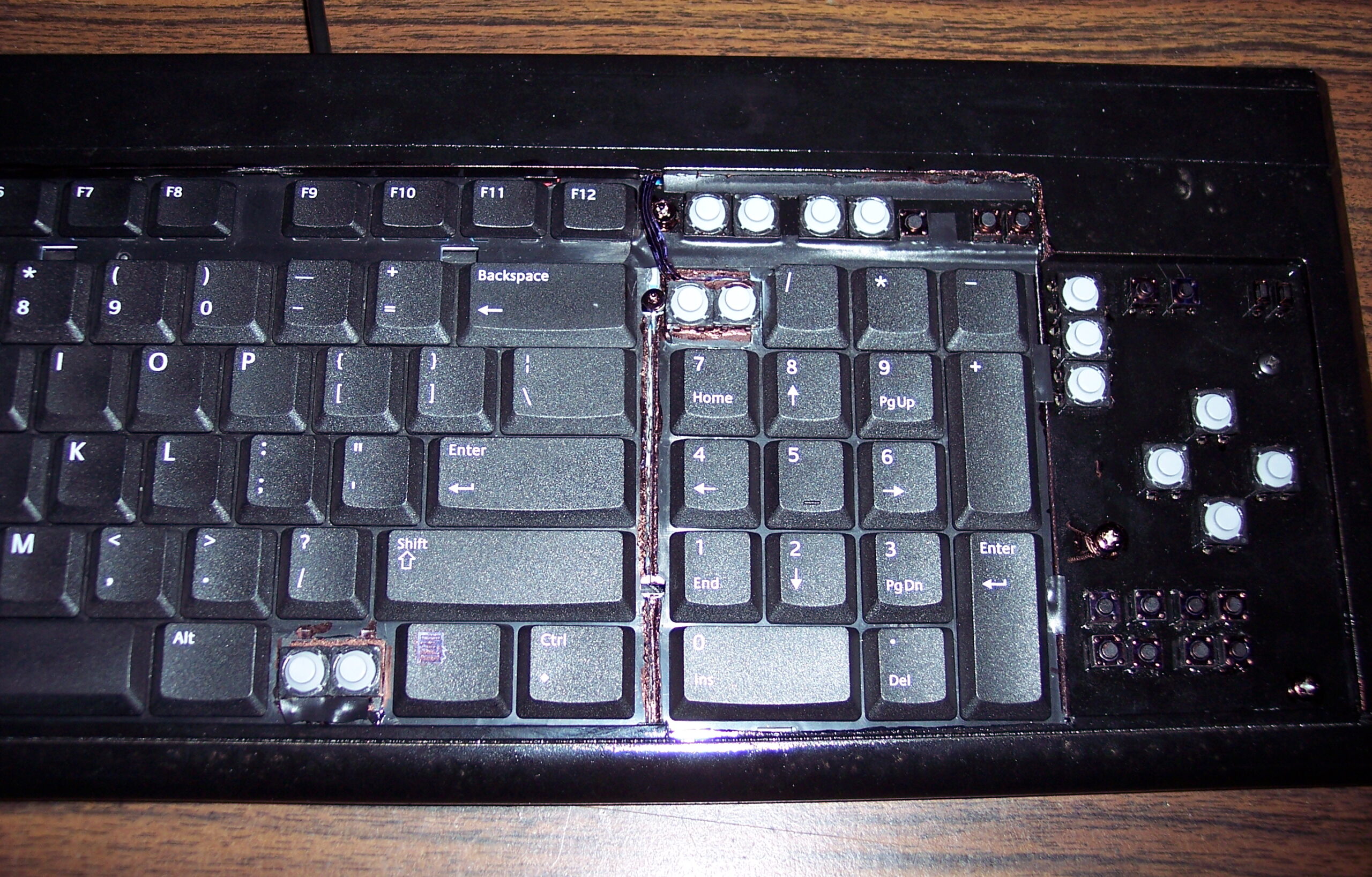
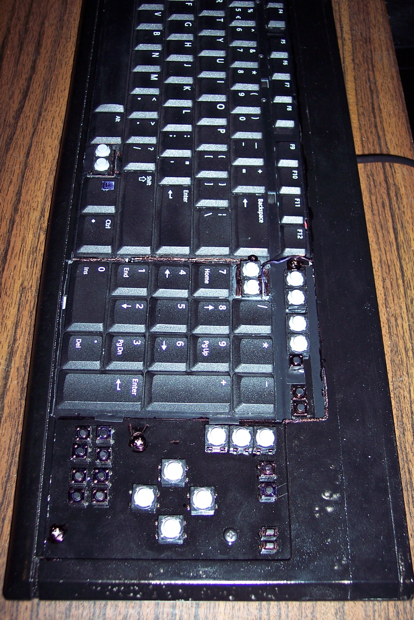
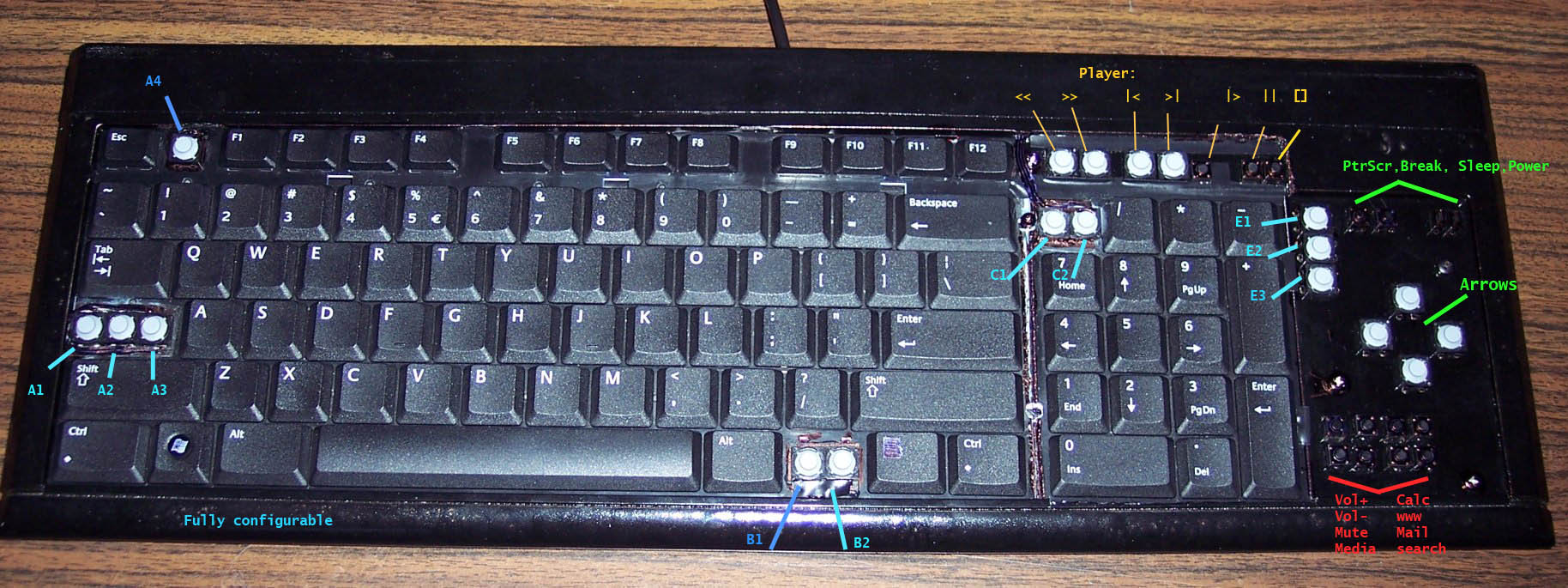
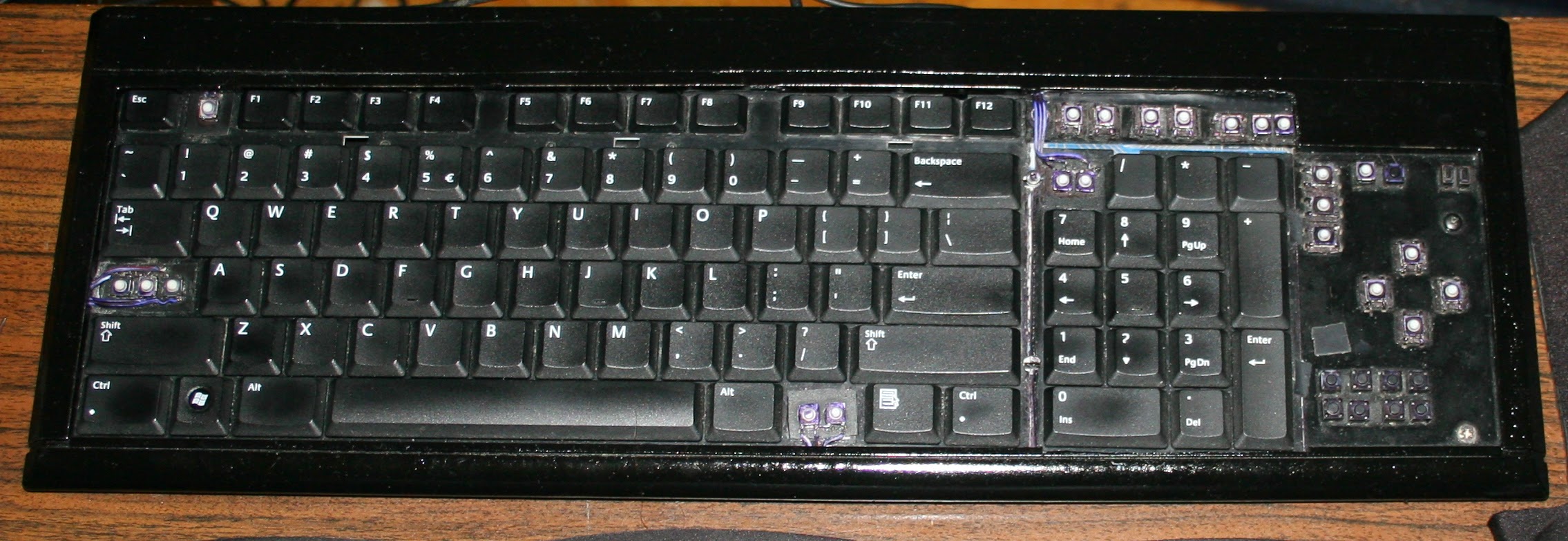
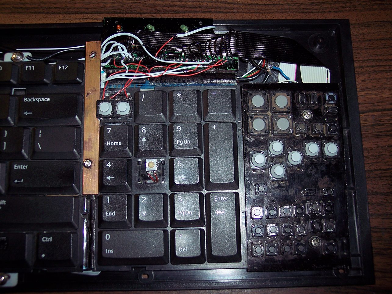
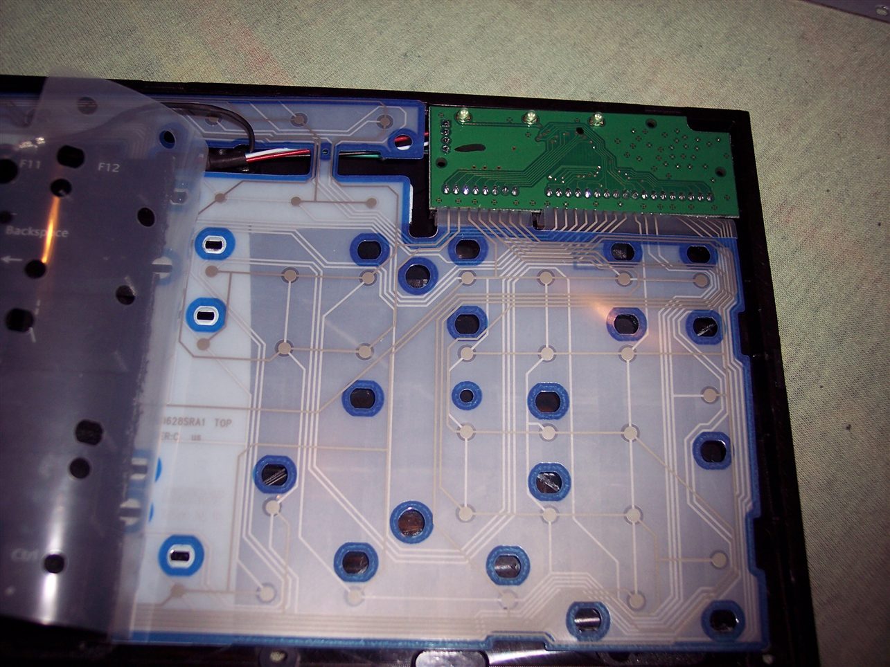
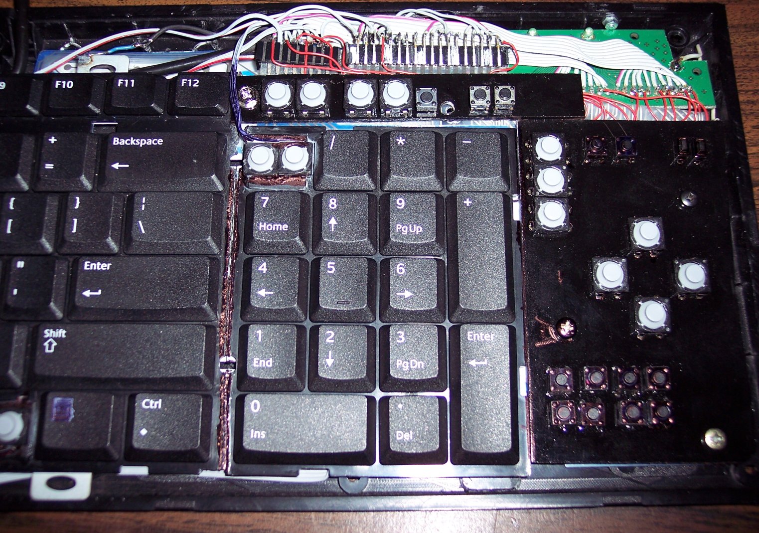
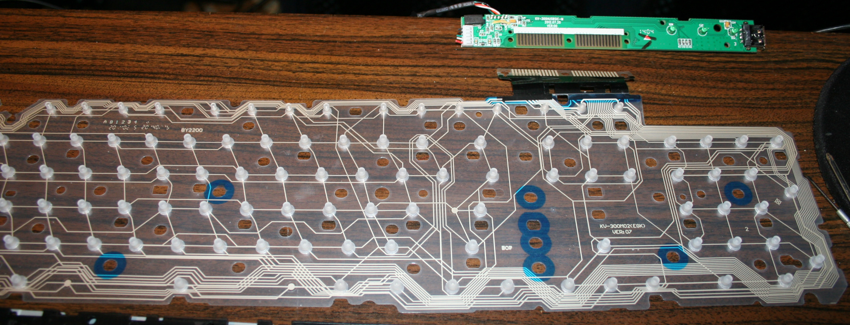
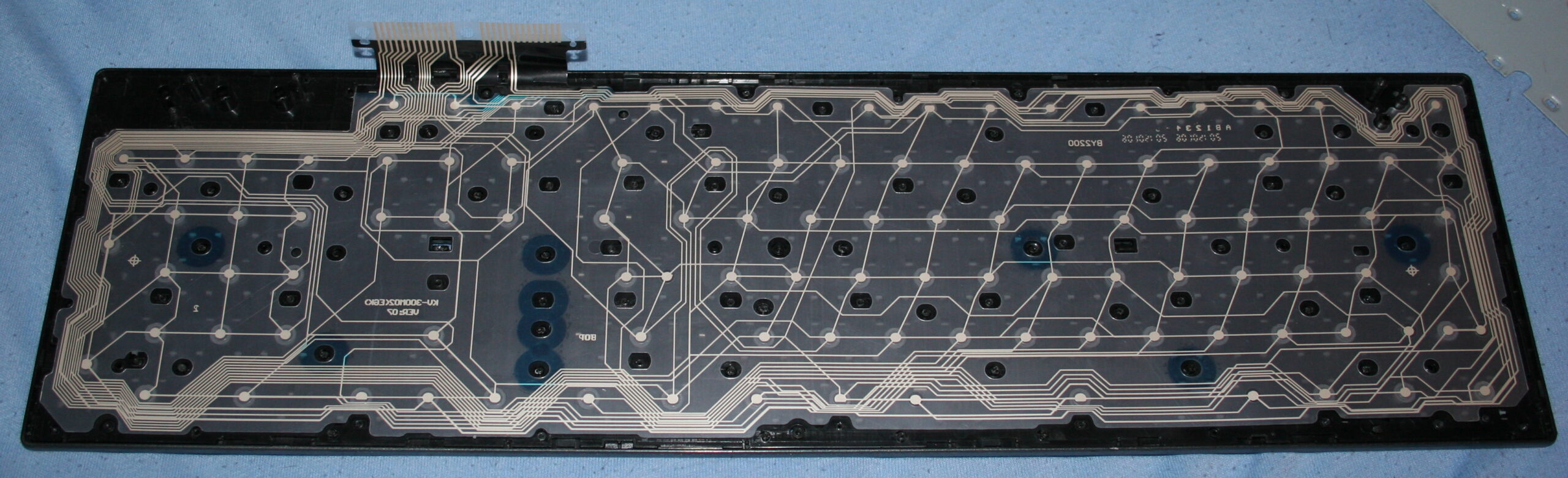
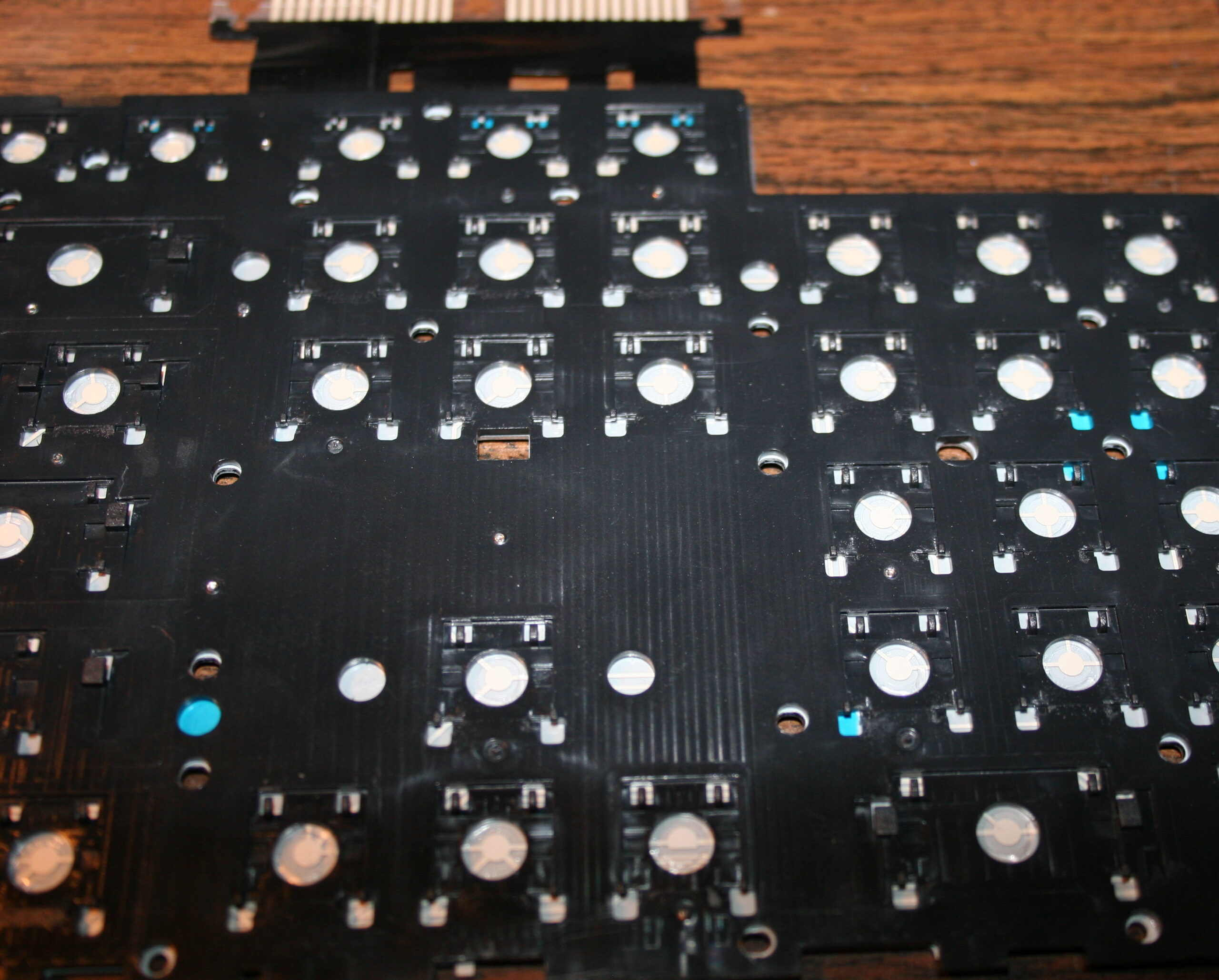
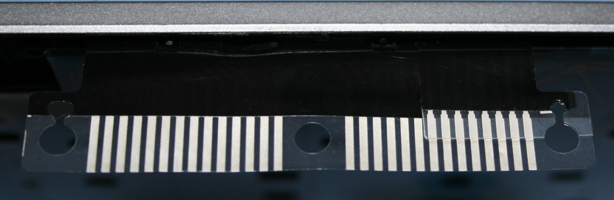
    The second step was removing the middle part with arrows. Which I find unnecessary and worse (less keys) than the same from numpad. In CK1 I’ve bent the foil and hid it under. It was risky, but the foil survived. The CK2 was different, it was made from two identical keyboards, thus no need to bend, only cut the metal and foil. That too was risky since the foil could have connections around the cut off part. It was only for numpad, the bigger part had whole foil under.

    Years later I modified CK2 further and bent the foil to create CK4 keyboard. And that’s 11 years already, so this would answer any doubts for longevity of such modifications. The number of times I disassembled it, changed something, and put it together is also quite high.

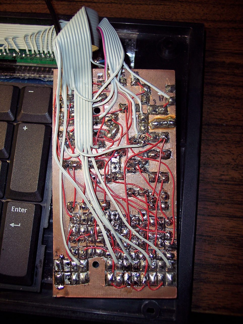
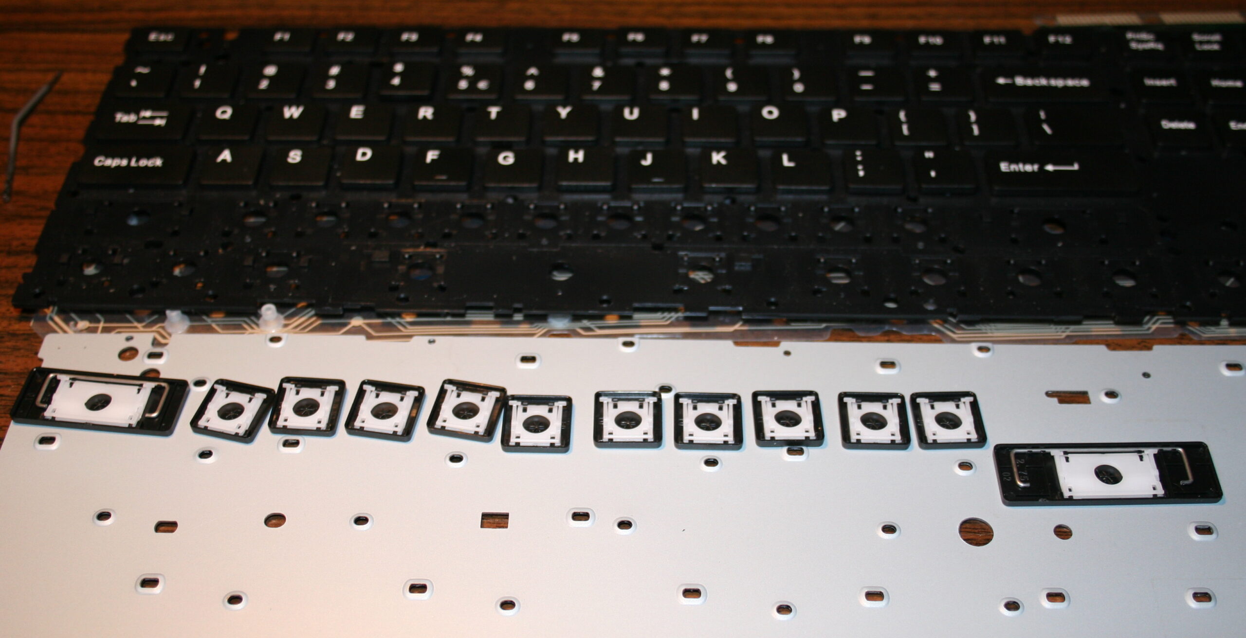
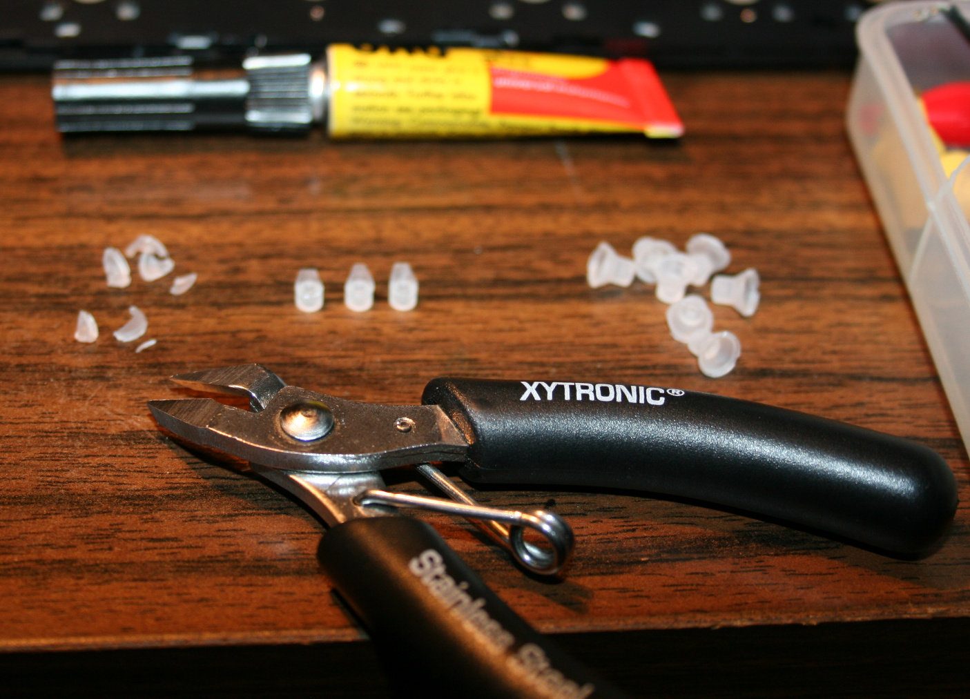
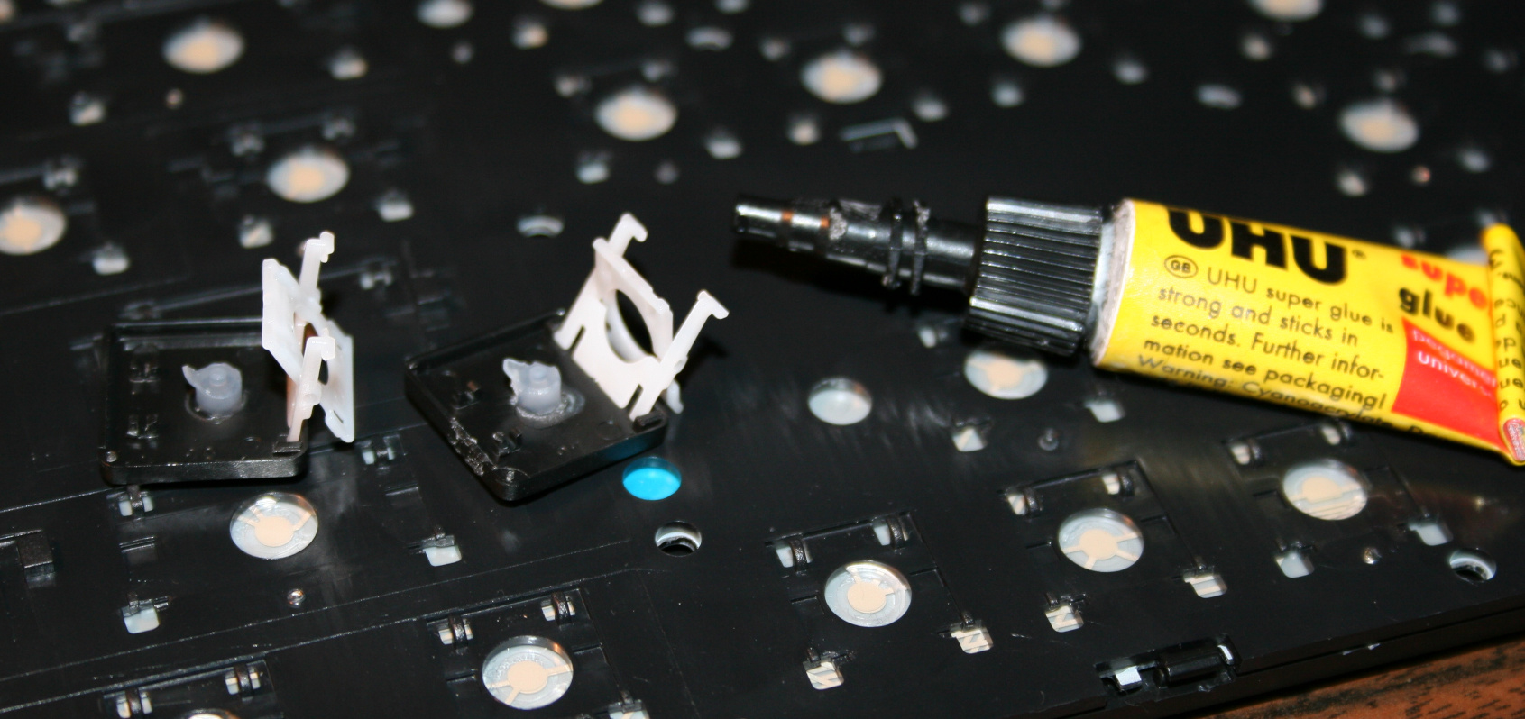
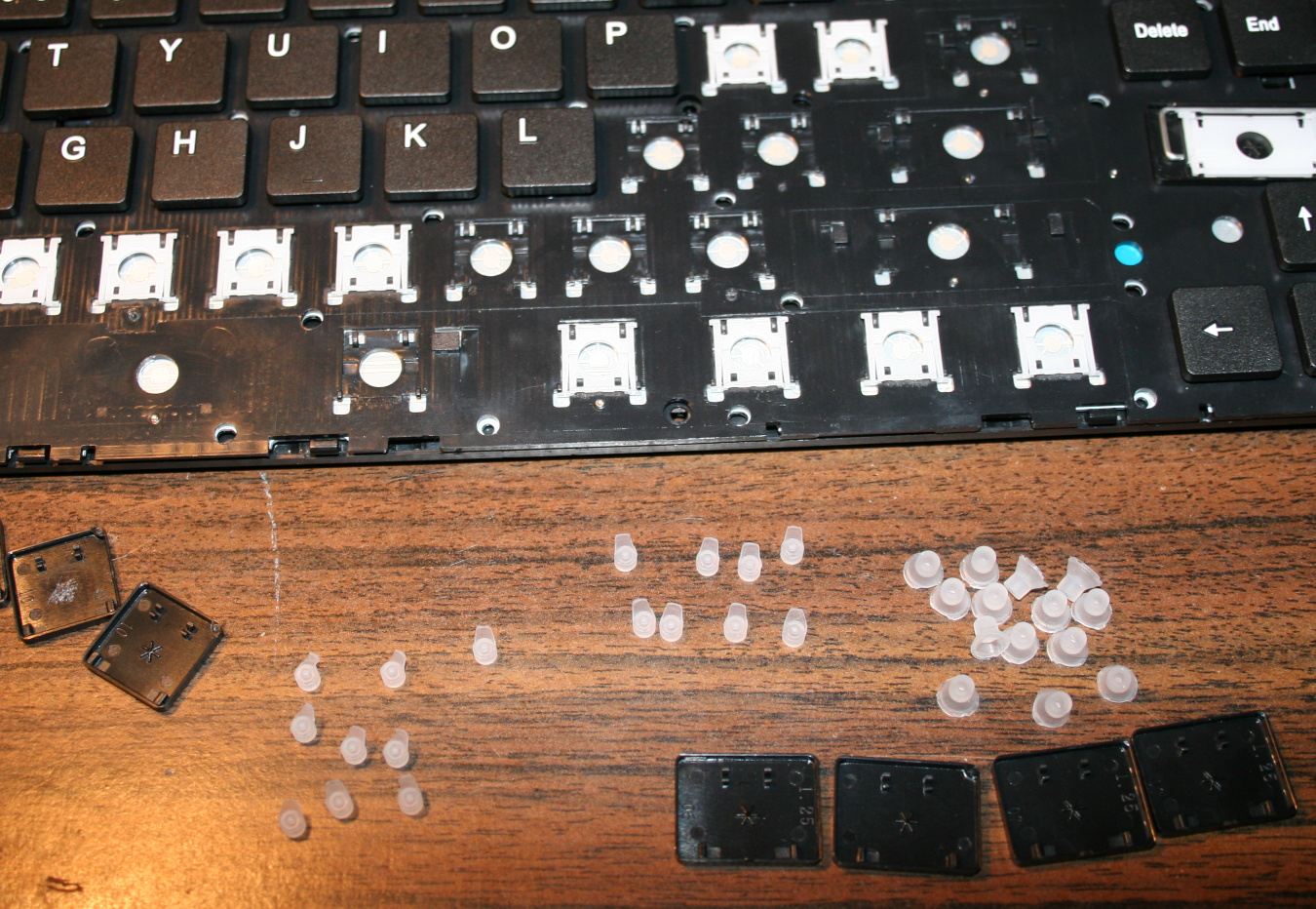
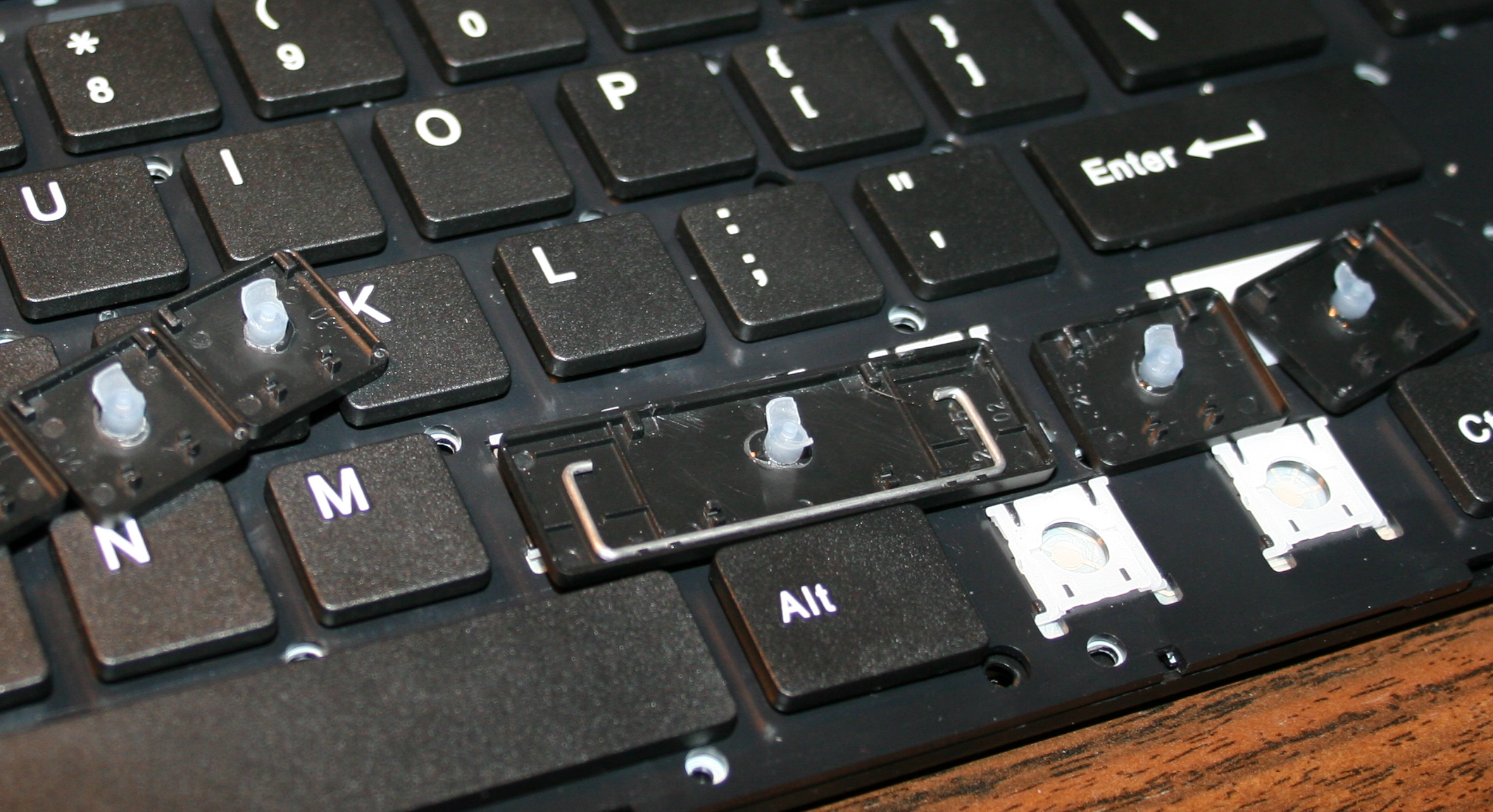
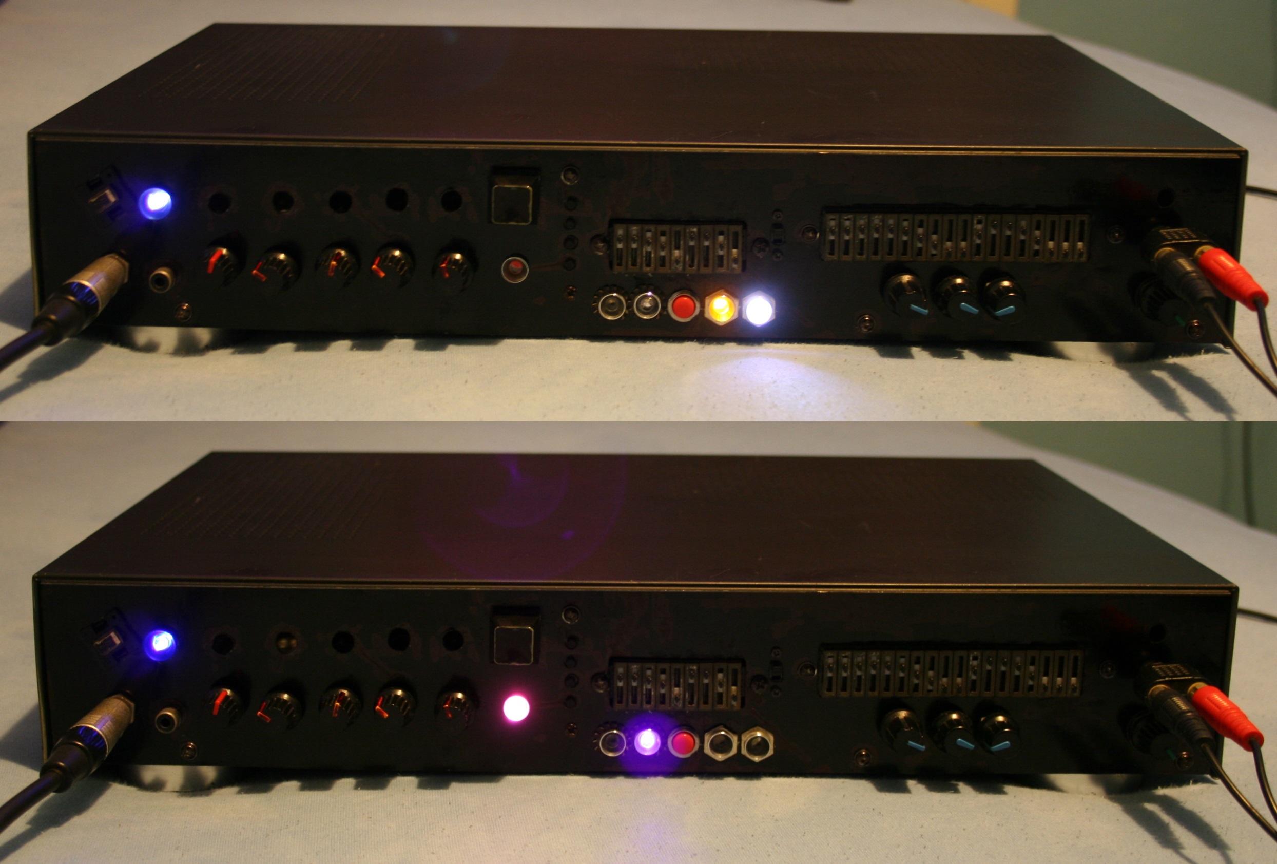
    The third step was adding extra keys. Using my oldest program for showing pressed keys and their codes, I figured out that there are more possible keys in keyboard matrix, that are just not connected. So I added them with wires and glued on keyboards. First as regular switches with metal domes, small and hard to press. Later using rubber switches, lighter to press. But turned out to be an even bigger fail since they wear out and stop connecting. They have some resistance too (like maybe 300 ohm) in addition to the resistance of foil traces (maybe 150 ohm). So finally I ended with the smallest metal dome switch I found, with force 0.5 N (50gf). It feels different than other keys but otherwise is good.
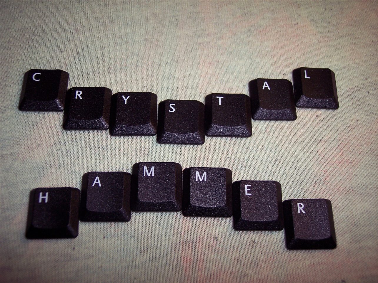
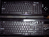
    📷Galleries

    The old galleries from my keyboards:

    CK2 final (2008)

    CK1 and 2 making of (2005 and 2006)

  • 2005-20 Keys light press mod

    2005-20 Keys light press mod

    ⏱️Overview

    This is a guide about my modification of reducing rubberdomes in keboards to acheive a light press effect. After this procedure keyboards can have much less actuation force (needed to press keys). It is separated from my other projects which describe my keyboard controllers.

    ✍️Motivation

    My motive is pretty straightforward: I want my keyboards to require as little effort to type as possible. And I don’t want any injuries from using my keyboards. These come from fatigue, which comes from more effort to press keys. I found once a pdf writing about this in detail, but don’t have a link.
    Fatigue also comes from lots of repeated pressing, but this is another thing. I can’t change it (much) if my hobby or work needs it. I do have helpers on display in my controllers (K.C. and K.C.4) showing: total/daily key press count, rate of key presses per minute, a graph with rate over time, and time I’m active typing without a break.
    So back in 2005 I saw those rubberdomes and thought: “how about I reduce them”. Then there was immediately this problem that they need to be glued back. Well after I did all that, it actually took like 2 weeks to get used to my modified keyboard. I wasn’t sure if this mod will last, but it did. After a while of using, it was easy to understand, that keyboards are really badly and cheaply made and I think it’s just a history thing (just like the thing about this idiotic Qwerty layout), surely not a sum of only intelligent decisions.
    I’m glad I did this process, and just before writing over 120 pages of my master thesis on this modded keyboard, which now was nice to use and wasn’t meant to injure me. I did a second one for work at some point.
    I remember once on a keyboard back there was a warning about possible injuries, seemed unreal to me back then, yet it is true, I even once made such mod for a person, who paid and even later thanked me numerous times, because he is suffering from that injury and such keyboard makes less pain to use.

    ℹ️Information

    Originally most keyboards need about 50 gram force to press keys, and probably 4 mm distance. After cutting, the distance is about 1-2mm, the force gets lower (and depends more on keyboard foil), e.g. 9 to 18 gram for CK5 (but 23 g for CK3, 33 g for CK4 etc). This can also be varied per key (more detail can be seen on pictures (galleries below), but ultimately the lowest 9 g value comes from keyboard’s foil thickness (and those 23 and 33 g values are higher because the foil was thicker in those keyboards).

    🛠️Modifications

    The first operation I do, is cutting off most of all rubber domes. I aim at minimized key pressing (actuation) force and also travel distance.
    This makes the keys much softer to press. If pressing needs less effort then it will cause less fatigue. It is simply more pleasant and comfortable. Also healthier, since the risk of keyboard injuries decreases.

    The second is glueing them back to keys. It’s required because they are glued to foil (mostly always).

    Everytime (except once in 2020) after doing the process, I am using the keyboard myself constantly. Thus if done right, there is no risk of any key failure.

    📜History

    I already did this first on my two oldest keyboards in 2005 and 2006.
    Then in 2015 for this keyboard (originally A4 Tech KV-300H) named CK5, and again later in 2020 (another same keyboard) making the process the video.
    Next for CK3 and CK4 in 2016, which later became CK6 and CK7, and CK6 became CK9 with KC4 in 2020.

    ▶️Videos

    Video guide showing the process here, for just a few keys.
    Another video of testing force with weights after.

    🪛Steps, guide

    Steps needed, shown in video:

    • Getting keys off from keyboard, using a tiny flat screwdriver.
      Pushing gently (but firmly) and leveraging tiny screwdriver in 1 corner, to pop the key’s scissor lift (white) out of its “half socket” from keyboard (not from top of key).
    • Getting rubberdomes off from foil, using just fingers, pinching with force.
      In laptop keyboards, the rubberdomes are separate and small.
      But on old very cheap keyboards there is 1 big rubber piece with them all. I didn’t try modding them.
    • Cutting off rubberdomes, using small side cutters.
      The more you cut off the less force and travel. But caution for bigger keys, especially Spacebar, they need a bit more rubber width left (or in 2 places) for same force, becuase they are heavier.
      I did reduce modifiers (Shift, Ctrl, Alf) keys and arrows completely, without that short supporting width, they’re just resting on keyboard foil, this gives only 9 g force. Value depends on foil, and not at all on rubber because there is none left.
      For most keys usually few mm width and height (3-5 mm or so) is holding it above foil.
    • Removing scissor plastic (white) from key (black), using a tiny flat screwdriver.
    • Optionally (if present) scraping that (stupid) star * pattern made on keys, to be flat. Can be scratched with cutters or screwdriver, may be even better so for glue.
    • Glueing (reduced rubberdomes) back to keys, using any superglue (cyanoacrylate based).
      Holding with tweezers or smallest pliers for a few seconds.
    • Waiting (best about 1 minute) until glue gets solid and ready.
      On video I’m actually making this too fast. Depends also on how good or fresh (after opening) the glue is.
    • Lastly mounting keys back, rather easy after knowing how the scissor keys work
    • Repeating for each key. Unfortunately it is really boring and tedious. Took me about 2 days for 1 keyboard.

    📷Galleries

    Light press mod 9-18g (CK5, from 2015)

  • 2003-04 Distortion X 🎸

    2003-04 Distortion X 🎸

    ⏱️Overview

    “Distortion X – The Great” was my final version of an analog guitar effect from 2004, and looked similar in 2003 already.

    📊Features

    It had a Distortion, Reverb / Echo and 2 Equalizers (9 and 18 bands).

    The Distortion featured such regulations:

    • Switch for Clean / Distorted mode, pink LED
    • Clean Volume
    • Drive (i.e. Distortion, Amplification)
    • Low Pass (filter frequency)
    • High Pass (filter frequency)
    • Balance (mix between the two filters)

    Reverb was made on the longer analog line MN3008.

    It had only 3 potentiometers (knobs):

    • Delay (i.e. Length: short would do Reverb and long did Echo, at reduced bandwidth)
    • Feedback (how much from output was summed back to input)
    • Volume (output mix between Reverb and clean)
    • Switch to turn on/off, white LED

    Equalizers were used only one at once. By default the Narrow one (9 bands) was for Clean mode and Wide (18 bands) was for Distorted, thus allowing more customization. Narrow had violet LED on left, and Wide had orange, on right.

    It also had 2 switched, one would exchange Narrow with Wide (so the opposite to default, Narrow for Distorted). And other switch was to turn equalization off, mainly just to check the difference, most left, red-orange LED.

    For a moment it had also the short Reverb / Flanger board with knobs, visible on pictures. But I didn’t use it. Power supply for it was different (not symmetrical) and that added more noise.

    📜History

    I was developing analog effects for electric guitar since we started playing in 2001. There were several versions of it. The 1st was just a distortion. The 5th had one 9 band equalizer and I think also a Reverb / Flanger on short delay line MN3007. The 8th was similar but had 18 band equalizer and long Reverb / Echo.

    Since I was playing backgrounds and my friend solos, we needed 2 effects. The 5th and 8th were separate and best combination. I was naming them using Roman numerals, so this one, X was the 10th and last version.

    ⏳Conclusions

    In 2004 I bought a digital effect, Digitech RP 200A, and first realized the huge difference between analog and digital effects. It was very feature rich and the sound quality was much better (probably like 20dB more, I guess my analog could be about 70dB SNR at best). Digital had many more effects like Chorus, Detune, realistic Reverb, high quality Echo, Cabinet models etc, and was stereo. But that model was very poor in regulations, there was only one parameter for each effect that could be changed (whole effect had only 3 nobs).

    So even though it was higher quality and had more features (but less regulations), I still used my Distortion for some time. Also since the digital sound and because we started college we stopped playing together so often and then at all. Also we had the digital one so I could just put all equalizers and reverbs in one. Then I finished it with a better case (from an Audio CD Recorder, which internals I moved to a worse case).

    ➡️End

    I sold it recently. For a ridiculous price, maybe just summing up to what parts had cost me. But there was a lot of time dedicated to developing it and making PCBs. But still, I’m glad I freed up cabinet space and didn’t have to throw it out (too sentimental to do that). Also got some money for it and somebody could find it useful or maybe even educational. I sold my guitars that year too. They were just gathering dust for too many years.

    It was great for what it was. It was the best I could make of what was possible at the time. Recently I thought a few times already, about how much easier and more advanced a digital effect processor could be made. For example Teensy 4.0 has a lot of power, ADC and DAC are available nowadays as codec chips rather cheaply and Teesny seems to be popular for music devices and similar projects. Maybe even slower MCUs could that earlier. Earlier I have even searched and found an already open source guitar effect, I forgot which was it, but searchin now gives even more results.

    📷Gallery

    Also with pictures of inside and schematics.

  • 2002-03 Tracker SXIV 🎶

    2002-03 Tracker SXIV 🎶

    ⏱️Overview

    This is the music tracker program I wrote around 2002-2003, in Delphi 5.

    It was 800×600 on a 17″ CRT back then, so already 4 screens fit now.

    ✍️Motivation

    I was having fun with Scream Tracker on DOS before, so it felt best for creating music and using only keyboard for that.

    I called my program simply the same way, but started with version 6 and increased until 14. Then shorted it to just S and used Roman numerals XIV.

    This was such an awesome program to use and look at. Mainly because keyboard shortcuts were customized to what I wanted, and also I implemented many quite useful operations in it, e.g. in patterns editor.

    🔍Implementation

    It was using GLScene package for Delphi and my colored bitmap fonts from another program (it was the predecessor to Crystal Font), hence so varying and colorful texts everywhere.

    By default I also used colored image backgrounds, since pages felt really empty. It even had animated text transitions for title pages text and a toggleable fire animation in corner 🔥.

    But it was complete garbage at the way sound creation was done. It simply relied on a system timer event and triggered sound playing from DirectSound buffers. I know, nobody does that for music. I didn’t know any other way to code this then.

    Timer was more or less stable, but I had to render very little while playing, mostly empty screen and 1 bottom line of info.

    🎵Music

    I made about 5 songs with it, more here. Also used it for percussion patterns when we were both playing electric guitars.

    Later I was checking out Renoise, but eventually my interest faded away from creating music.

    Recently I found Furnace tracker (for chiptune music) to be very cool and FOSS, sources here.

    📷Gallery

  • 1997-2022 Kitchen HiFi 📻

    1997-2022 Kitchen HiFi 📻

    ⏱️Overview

    This will be a somewhat unusual project post. I normally don’t show off stuff that didn’t need much creative work, but in this case it has a very long history (since 1997). It has gone through many modifications and it is still used every day, now in our kitchen for playing music.

    📜History

    It all started as a Panasonic RX-FT530 Dual Cassette Player. My mom bought it for me in 1997 (its production date inside has 1995), before I started technical high school. It was also around the date when I started learning electronics in practice and later in theory (from 20 years ago) at school.

    Since then it has gone many changes and had lots of features, many of them aren’t present now:

    • Blue LED for radio stereo indicator. Obviously, the first thing to do.
    • A switch for super fast cassette rewinding (Do feel free to spool through). Tape looked after a bit uneven inside, but very useful.
    • Green LED lights under both cassette decks (in middle) to see where the tape is at (how much on left and right barrel). Also extremely useful.
    • I removed the closing decks, and was just having cassettes clearly visible while using.
    • A small LED for the marker on frequency ruler for analog radio. I think it broke at some point leaving me without a ruler. I guess due to putting it apart and together again, fast and too many times, while not caring much where I place its parts.
    • Not sure when, I splashed it with (white, silver and gold) oil paint?, from PCB markers I had back then (obviously too many).
    • A digital clock, at some point on right side. Wasn’t very accurate so it didn’t last long there. Left a switch and 4 places after its buttons in back though.
    • More input sockets, output audio socket to other amplifier, switch for it etc.
      I remember at some point of experimenting with other amplifier I accidentally put like -30V into HiFi, killing its power AMP chip. Which I then replaced, was a good challenge. While still being a teenager I obviously needed this HiFi.
    • Since these became not needed later, all holes got covered with black tape (at least 10 already, in total).
    • At some point I added a 5V regulator 7805 and USB sockets so I could power other devices from HiFi, e.g. a clock
      (Instead of ridiculous AA batteries. One can use a 3V regulator or a resistor (e.g. 200Ω) with 3V zener diode).
    • It has spent a few years, abandoned in cellar. Gathering dust and wishing for a better future.
    • Many years later, I ended my history with cassettes (recorded them on PC into FLAC and OGG, and threw out after).
      In 2020 the cassette decks (with all that mechanical nonsense and engine) flew out to electronic garbage bin too. It was just the amp and radio then.
    • I wanted to have a digital radio, that stayed at given frequency. And BTW a MP3 / USB player, why not.
      So I ended buying a cheap, local, 2nd HiFi (anyway with Chinese components) which just featured both. It had crappy sound due to small speakers (no bass at all), we used if for short, but naturally I wanted to merge its insides into my old speakers from Panasonic.

    🔍Details

    The final “HiFi” currently features a digital radio, USB or SD card player (from that 2nd cheap “HiFi” product) and analog input.
    Its radio forgets frequency after power off though, so power is always on. It was too in Panasonic, IDK why, using about 0.5 to 1W constantly, power amp is likely always on.

    I scrapped that stupid Class D amp (MIX3018) from 2nd HiFi, I prefer that AB, although it has too much power. Then located its audio outputs and connected to old LA4108 power amp (low quality, too much power), but with better quality anyway.
    Later I also added a double potentiometer (which I even had available) for volume on front, since the original was making noise when turning.

    I will eventually just use op-amps to speakers someday, and will throw out the big old PCB too, from which just 20% is now used. Then it will be just speakers and case from the oldest HiFi.

    There are now 3 extra buttons on top (power on/off (hold) / input, next and previous) to control 2nd HiFi. Light press switches, 0.5N force, my favorite. I put rubber cover on top, to protect form any liquids💧, this is kitchen after all🫖💦.

    For a while I had a cheap tiny Bluetooth receiver in analog input, powered from USB, but I dropped it, too much noise and once a while it did reconnect etc. Audio cable is more reliable, even cheaper.

    I still use its regulated 5V outside but in different connector (PC like), to power an outside thermometer (was from a PC case) and a digital LCD clock.

    Lastly I added a small white LED lamp, that’s always on, and helps moving around the kitchen at night, before reaching main light switch.

    ⌛Conclusions

    So: why didn’t I just buy a new HiFi that already has all those features, instead of continuing with this old junk?
    Several reasons:

    • Firstly, there is no such thing as a product that has all features / properties that I need, with proper control and interface (knobs, convenient buttons, menu, etc). This can only be achieved by continuing to develop it myself according to my current needs.
      I now see all electronics products just as ingredients for further modification. Ideally I would create one from start, but that’d be too much time and effort spent, just for our kitchen.
    • Secondly, I am an anti-consumer, I usually hate buying. It needs a lot of time for research, to find a product that is closest to: not a hoax/hype, reliable, functional, fair-priced, still cheap, durable (will work for long), allows repairs, looks okay, black, etc. (all at once; add needed, strike out not needed ?). On top of that I don’t like spending money (I like saving it) to support companies, which constantly produce (soon-to-be) garbage.
    • Lastly, it is a fun and easy hobby that grants better more customized products for daily use.

    📷Gallery

    It has pictures from 2020 and up, showing old look and the newest merge of 2 HiFis. Needless to say, their cases weren’t compatible at all, so there is a lot of black tape around.

  • 2000-01 Drawings 🖌️

    2000-01 Drawings 🖌️

    ⏱️Overview

    These are decorative texts, drawn on paper. I was using (up to) about 26 colorful gel pens and few regular ballpoint pens too. The text in this picture is Experience (my favorite one).

    ✍️Motivation

    Back in technical high school I was very disappointed at the level of education there (mainly stuff from 1980). And also extremely bored, especially on history and Polish (literature) lessons 🥱.

    After all, that stuff was already in the elementary school, and I thought I will get rid of those crappy non technical subjects.

    I never accepted the garbage I had to learn and did only bare minimum. There was no chemistry at all and history was for 4 (of 5) years? Now that was serious bullshit 😡.

    So yeah, this was my sudden and creative outcome at the time, which (at least partially) fixed the boredom and made something cool with the time. I didn’t expect it would happen.

    🔍Details

    The words in pictures from gallery are as follows:

    • Cathedral, Catedral (t upside down), Experience, Revolution, Reality. The rest is easy to tell.

    The green crystal hammer style is quite different and funny, normal one is the violet.
    There is also the eye gem symbol, a simpler version from my later painting. I only drew 2D things.

    📷Gallery

    Full gallery with more below: